To be published in Computer Aided Radiology and Surgery (CARS 2004)
IGSTK: a software toolkit for image-guided surgery applications Kevin Cleary a
a,*
b a c , Luis Ibanez , Sohan Ranjan , Brian Blake
Imaging Science and Information Systems (ISIS) Center, Department of Radiology, Georgetown University, Washington, DC, USA b Kitware Incorporated, Clifton Park, NY, USA c Department of Computer Science, Georgetown University, Washington, DC, USA
Abstract. The Image-Guided Software Toolkit (IGSTK: pronounced IGstick) is a high-level opensource component based software toolkit. The toolkit is currently under development and is intended to make it easy for researchers to prototype and develop image-guided surgery applications. The toolkit has been used to develop an example application incorporating electromagnetic tracking of a surgical needle. This paper presents the development approach, the requirements defined, the components identified, and the example application. Keywords: open-source software; image-guided surgery; software toolkit
1. Introduction The Image-Guided Software Toolkit (IGSTK: pronounced IGstick) is a high-level component based software framework providing common functionality for image-guided surgery applications. The toolkit is based on open-source standards. The toolkit consists of a set of high-level components (2D and 3D viewers, tracker interfaces, registration modules, etc.) integrated with other lower level open-source libraries and application programming interfaces (APIs) from hardware vendors. The toolkit is built on the Insight Segmentation and Registration Toolkit (ITK) and the Visualization Toolkit (VTK). The toolkit will allow researchers to quickly build prototype systems for imageguided surgery for specific applications such as minimally invasive cancer treatments, vascular interventions, and percutaneous spinal procedures. The toolkit has been used in our laboratory to develop an image-guided surgery application incorporating electromagnetic tracking for minimally invasive abdominal procedures. The paper is organized as follows. Section 2, methods, presents our development process and enumerates the requirements developed and components identified. Section 3, results, shows our example application. Conclusions are given in Section 4.
*
Corresponding author. E-mail address:
[email protected]
Page 1
To be published in Computer Aided Radiology and Surgery (CARS 2004)
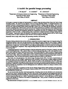
2. Methods The toolkit was developed using a combination of traditional top-down programming approaches (Rational Unified Process [1]) and extreme programming methods (agile programming). A new software approach called Component-Based Product Line Analysis and Design (C-PLAD) was developed as part of the toolkit project. C-PLAD is divided into six high-level phases. These phases are Specification, Requirements, HighLevel Use Cases, Component-Level Use Cases, Software Design and Development, and Testing. The software design and development phase and the testing phase are iterative phases. The C-PLAD process is illustrated in Figure 1.
Fig. 1. Component-based product line analysis and design (C-PLAD) – six high level phases
As shown in Figure 1, the phases are as follows: 1. Specification. The initial system description is written as a problem statement. 2. Requirements. A set of requirements is then established to scope the project. 3. High-Level Use Cases. Use case templates are used to characterize the product. 4. Component-Level Use Cases. A step-wise iterative process for extracting component-level use cases from the high-level use cases is employed. 5. Software Design and Development. Structural and dynamic views (class and sequence diagrams, respectively) are created to represent each component. 6. Testing. The testing phase is an iterative phase with the software design and development phase. Testing is built-in from the beginning.
Page 2
To be published in Computer Aided Radiology and Surgery (CARS 2004)
As an example of one of the phases, the requirements definition phase will be described here. To identify the software requirements of the toolkit, a problem description or specification was drafted based on input from both subject matter experts (SMEs) and software developers. The group of SMEs included surgeons, radiologists, and image analysis experts. This problem description was produced from the analysis of typical image-guided surgery applications. Application-specific requirements, called features, were defined in addition to software-specific system requirements. This separation of functional (features) and nonfunctional (software specific) requirements is important to the reusability and portability of the system. The functional requirements are those that will be perceived by clinicians while they are using image-guided surgery applications, for example the capability of the system for performing electromagnetic tracking and providing image overlay. The non-functional requirements are mostly of interest for the software engineers engaged in the implementation and maintenance of the applications, for example the capabilities of the system for generating C++ exceptions in order to manage error conditions. The requirements were captured and managed using Rational Requisite Pro. Requisite Pro provides capabilities to document and manage various aspects of the requirements, such as priority, predicted difficulty, the status, and the assigned developer. In addition to this meta-information about the requirements, Requisite Pro has capabilities to support traceability to later software design and testing. Moreover, Requisite Pro facilitates the separation of functional requirements (FEAT) and software-specific nonfunctional requirements (SOFT). A sample of the high-level requirements taken from the Requisite Pro tool is shown in Table 1 and Table 2. Table 1. High-level functional requirements (FEATURES)
FEAT1: Read and Process Information from CT and MR Scans The system shall have the ability to read CT and MR scans in DICOM format. FEAT2: Interface to Electromagnetic Tracking Hardware The system shall support interface functionality to the AURORA electromagnetic tracking hardware. FEAT2.1: Hardware Control The system shall provide control interfaces to the the tracking hardware. FEAT3: Graphical User Interface and Visualization Functionality The system shall support software functions to graphically display CT images. FEAT3.1: Four Quadrant View The system shall support a four quadrant display for axial, saggital, coronal, and three dimensional views. FEAT3.2: Slice Selection, Panning, and Zooming The system shall support an ergonomic mechanism for selecting slices, zooming and panning. FEAT4: Segmentation The system shall allow the user to segment/detect surgical instruments from intra-operative images. FEAT5: Registration The system shall provide image registration functionalities in order to overlay pre-operative and intra-operative images.
Page 3
To be published in Computer Aided Radiology and Surgery (CARS 2004)
Table 2. High-level nonfunctional requirements (SOFTWARE specific)
SOFT1: Common Services The system shall support common system-level functionality. SOFT1.1: Information Management The system shall have support for storing and logging results. SOFT1.2: Exception-handling The system shall support the capturing and presentation of software exceptions. SOFT1.3: Problem Resolution The system shall support functionality to assist users/developers in solving problems. SOFT2: Component Capabilities The system shall provide general interfaces in support of future software expansion and composition. SOFT3: Developmental support The system shall provide specific documentation and process support for system evolution and enhancements. After the requirements were defined, high-level use cases were identified to help identify a set of common components. The components that have been identified to date are listed in Table 3. Table 3. Image-guided software toolkit (IGSTK) components
Control Components Application Container Component Workflow Control Component User Interface Components User Notification Component 2-D Viewer Component (Axial, Saggital, Coronal, MPR) 3-D Viewer Component (Surface rendering) 3-D Volume Viewer Component (Volume rendering of CT/MRI) Image Input Components Video Input Component (Fluoroscopy) DICOM Reader Component
Common Service Components Logging Component Error-Handling Component Parameter-Management Component Error-Handling Component Registration Components Organ Model to Image Registration Component Fluoroscopy to CT Registration Component Segmentation Components Surgical Instrument Segmentation Component (Must be targeted by application, e.g. needle, guidewire) Tracker Components Tracker Interface Component Electromagnetic Tracking Optical Tracking
Page 4
To be published in Computer Aided Radiology and Surgery (CARS 2004)
The components implemented during Phase I of this project were developed in C++ since this is the programming language in which FLTK, ITK and VTK have been implemented. C++ provides an optimal trade-off between high-level programming capabilities, generality, and run-time performance. The implemented components were placed under CVS (concurrent version system) control in a central repository. Configuration files for CMake were created for the library of components and the prototype applications. A quality control dashboard managed by the Dart tool was configured in order to receive the submissions of tests performed with IGSTK components on any other platform, for example, software regression tests performed at Georgetown University can be submitted to Kitware’s Dart web server. The software process we are using is described in [2]. Figure 2 presents a screenshot of the quality control Dashboard for IGSTK. On this particular date, six different computers submitted the results of testing suites to the Dashboard. Among these six machines, the code has been tested with three different compilers. Since IGSTK is intended to be used in the clinical environment, a very stringent quality control system has been devised to ensure high levels of robustness and reliability.
Fig. 2. Quality control Dashboard for IGSTK
Page 5
To be published in Computer Aided Radiology and Surgery (CARS 2004)
3. Results The toolkit was used to develop an image-guided surgery application based on electromagnetic tracking. The graphical user interface (GUI) from the software application is shown in Figure 3. The GUI was developed using FLTK and the components were created using VTK and ITK. The set of components developed were: a. DICOM reader component: The purpose of this component is to read the DICOM data volume of interest. The input to this component is the directory where the DICOM files are located. This component figures out the different series data available in the directory and presents the list of series to the user to select the series of interest. After the user selection, the component reads the files in the series, and returns the volume data. This component uses ITK and FLTK classes. b. 2D viewer component: This component displays 2D slices from the read volume data. The user has the option to select Axial, Coronal or Saggital orientations for display. The display window has a slider control for selecting the slice of interest for display. This component uses VTK classes. This component also facilitates recording the point of the left mouse button click on a displayed slice through the use of the Event-Observer framework of VTK. In the application, we use three instances of this component, one for the axial, coronal and saggital views. In addition, with the left mouse button click on any view, we change the slice of display of other views to show the point of click. We also show the volume image of the needle (when active) in the views. c. 3D viewer component: This component is for volume rendering of the data. This component uses VTK classes. The component has options for rendering iso-surfaces within the volumetric data, maximum intensity projection of the volume, or render volume with an alpha compositing technique. This component utilizes the level-of-detail approach in VTK for improving performance during interaction. d. AURORA electromagnetic tracker interface component: This component facilitates tracking the needle. A sensor coil is embedded in the needle and used for tracking the needle. The field generator and the sensor coil are connected to a system control unit. The computer communicates with the system control unit through a RS-232 serial cable. The component currently is AURORA (Northern Digital Inc.) specific. e. Similarity registration component: This component facilitates registering between the CT space and the AURORA Tracking Space. The inputs to the component are the number of fiducials and their location in the CT space and the AURORA tracking space. From this data, the component does a best fit mapping between the two spaces.
Page 6
To be published in Computer Aided Radiology and Surgery (CARS 2004)
Fig. 3. Graphical user interface from example application
4. Conclusions A component-based software toolkit for image-guided surgery applications was developed. The toolkit is based on open-source standards and the software packages VTK and FLTK. The toolkit was used to develop a prototype application incorporating electromagnetic position sensing. The toolkit will be freely available for both research and commercial applications. The toolkit should enable developers to quickly build prototype applications. We hope to release the initial version of the toolkit in the public domain by the end of 2004. Acknowledgements This research is supported by the National Institute of Biomedical Imaging and Bioengineering (NIBIB) at the National Institute of Health (NIH) under grant R41 EB000374-01A1 and by U.S. Army grant DAMD17-99-1-9022. The content of this manuscript does not necessarily reflect the position or policy of the U.S. Government. The authors thank would like to thank Will Schroeder of Kitware, Stephen Aylward of the University of North Carolina, Kevin Gary of Arizona State University, and James Kenner of Wisdom Software for their contributions to this effort. References [1] Kruchten, P. The Rational Unified Process: An Introduction. Second Edition, Addison-Wesley, 2000. [2] Schroeder WJ, Ibanez L, Martin KM. Software Process: The Key to Developing Robust, Reusable and Maintainable Open-Source Software. To be published in proceedings of the IEEE International Symposium On Biomedical Imaging (ISBI2004), Arlington, Virginia, April 2004.
Page 7