system under sunlight, to photometric stereo with external lights, and to insensible image embedding. 1. Introduction. S
Illuminant-Camera Communication to Observe Moving Objects under Strong External Light by Spread Spectrum Modulation Ryusuke Sagawa and Yutaka Satoh The National Institute of Advanced Industrial Science and Technology Tsukuba Central 1, 1-1-1 Umezono, Tsukuba, Ibaraki 305-8560 Japan {ryusuke.sagawa,yu.satou}@aist.go.jp
Abstract Many algorithms of computer vision use light sources to illuminate objects to actively create situation appropriate to extract their characteristics. For example, the shape and reflectance are measured by a projector-camera system, and some human-machine or VR systems use projectors and displays for interaction. As existing active lighting systems usually assume no severe external lights to observe projected lights clearly, it is one of the limitations of active illumination. In this paper, we propose a method of energy-efficient active illumination in an environment with severe external lights. The proposed method extracts the light signals of illuminants by removing external light using spread spectrum modulation. Because an image sequence is needed to observe modulated signals, the proposed method extends signal processing to realize signal detection projected onto moving objects by combining spread spectrum modulation and spatio-temporal filtering. In the experiments, we apply the proposed method to a structured-light system under sunlight, to photometric stereo with external lights, and to insensible image embedding.
1. Introduction Some computer vision methods utilize light sources that actively change the illumination to capture images instead of acquiring images under uncontrollable ambient light. This contributes to simplify the problem and improve the performance of image processing. Various types of lights are considered as light sources, including video projectors, PC monitors, LEDs, and laser lights. We have named the system consisting of light sources and cameras the illuminant-camera system. An illuminant-camera system captures images by using a camera to change the projecting lights spatially and temporally. The system transmits illuminant light and uses a camera to receive the light directly or indirectly; thus the
problem of the illuminant-camera system is regarded as one of a communication system between the illuminant and the camera. One of the characteristics is that the communication channel is the light that travels in 3D space. One of the advantages of recent cameras is the high resolution, whereas the disadvantages are a low signal-tonoise ratio (SNR), low dynamic range, and low frame rate. Many image processing algorithms utilize high resolution by using spatial signal processing, for example, to reduce noise to compensate for the above disadvantages. However, an illuminant-camera system can transmit temporal signals from the light source to the camera by changing the light patterns. Moreover, light sources such as LEDs and lasers, which can change the light rapidly, and high-speed cameras, which can acquire images at a high frame rate, are currently commonly available. If these devices are used, a long temporal signal modulated at high frequency can be used for image processing. In this paper, we propose a method that solves the problems associated with illuminant-camera systems based on the spatio-temporal signal processing of optical communication between illuminants and cameras. One of the disadvantages of illuminant-camera systems is the weakness against external lights because it is necessary to block the light from external lights to observe light from the illuminants of the system. On the other hand, radio communication in noisy environments has been realized. Therefore, we propose signal processing that realizes an illuminant-camera system under strong external light such as sunlight based on the idea of temporal signal processing of radio communication. This paper describes the signal processing for illuminant-camera system. This enables the system to observe moving objects under external lights based on direct sequence spread spectrum (DSSS), which is used in wireless technologies such as code division multiple access (CDMA) and Wi-Fi. We apply the method to three illuminant-camera systems in this research. The first is a structured-light system of spatial encoding for 3D reconstruction. As structured-light systems of temporal encoding change patterns and capture
5097
multiple images, the temporal pattern is used to find the correspondence between projector pixels and camera pixels. The methods of spatial encoding do not use temporal information because they find correspondence by using a single image. Therefore, the proposed method utilizes temporal information to improve the SNR instead, and realizes an illuminant-camera system using a light source of much lower energy than external light, including sunlight. The second system is photometric stereo, which illuminates an object from various direction. The basic method of photometric stereo is time-division approach to turn lights on in a specific order. The proposed method discriminates among multiple lights illuminated simultaneously by using code division even under external light. The third method involves embedding information in a video. Because the light signals transmitted by the proposed method are high frequency and low energy, it is difficult to recognize by human eye. The proposed method superimposes signals detected only by a camera on video visible to the human eye.
2. Related work Wireless communication devices such as mobile phones realize telecommunication using low-power transmitters. Because many sources of noise exist in the environment, the receiver needs to distinguish the signal from the corresponding transmitter. CDMA is one of the techniques used in radio communication, for example, in mobile phone technology and Wi-Fi. CDMA extracts signals from a specific transmitter using the modulation based on spread-spectrum technology. Direct-sequence spread spectrum (DSSS) is a spread-spectrum technology. DSSS realizes robust communication against the interference of noise and unrelated signals by spreading narrowband transmitted signal over a large bandwidth [5]. Infrared and visible light communication have been realized as types of optical wireless communication. The removal of noise from ambient light is an issue in optical wireless communication. Some studies [1, 6, 9] have proposed noise removal based on DSSS. Because a camera observes a few light sources directly for serial communication between light source and camera in these methods, the advantage of the high-resolution camera is not utilized. In this paper, we propose a method in which every pixel receives different signals to utilize the high resolution. Methods known as multiplexed illumination have been proposed. These methods decompose an image of a scene that is simultaneously illuminated by multiple light sources to multiple images of the scene illuminated by each single light source. Schechner et al. [15] proposed a method of illumination based on Hadamard-based multiplexing by projecting multiple lights using each pixel of a video projector. The multiplexed illumination contributes to improve
the SNR by multiple acquisition of an object illuminated by each light source, which is based on a method to improve the SNR for spectroscopy [4]. Mukaigawa et al. [8] proposed a method to estimate the bi-directional reflectance distribution function (BRDF) of the surface of an object by illuminating from various directions based on Hadamardbased multiplexing. These methods observe static objects by multiplexed illumination. Wenger et al. [16] proposed a method for relighting images of moving persons using video captured with Hadamard-based multiplexed illumination. Although multiplexed illumination basically assumes that a static scene is observed to demultiplex, the method introduced motion compensation by calculating optical flow to demultiplex the lights projected onto a moving person in the video. In this paper, we propose an approach based on signal processing to observe moving objects without tracking them. One of the advantages of spread spectrum methods is that it is possible to demodulate the signal even when the power of noise is larger than that of the signal. If the illuminant of the signal itself emits light other than the signal, it becomes difficult to recognize transmitting signal. Namely, it means that insensible signal can be embedded in visible pattern. Methods required to embed information in an image are known as information hiding or steganography. A basic approach involves embedding the information in the least significant bit. In this regard, methods based on spread spectrum method [7] have been proposed. Although the method assumes digital communication, we propose a method of information hiding for illuminant-camera system. Some studies have proposed structured-light systems under strong external light. Gupta et al. [3] proposed a system under strong ambient illumination by concentrating the power of projected light on one line. Compared to sunlight, the SNR is improved by projecting light onto 1D line instead of onto a 2D area. O’Toole et al. [10] proposed a structured-light system with a scanning-based laser projector and a rolling shutter camera. By aligning the scan lines of the laser projector and camera, the camera pixels are efficiently illuminated by laser light during the exposure time. The SNR is improved compared to external light and the structured light is detectable even under sunlight. However, these methods are based on time division to improve SNR, the proposed method is based on code division.
3. Illuminant-camera communication using spread spectrum modulation In this section, we define the problem of an illuminantcamera system as a problem of communication between the illuminant and the camera, and propose a method of communication based on DSSS, which is one of spread spectrum modulation. The advantage of spread spectrum mod-
5098
M
M
Signal value
0.5 0.0
2
2
1
1
0 −1 −2
−2
−1.5
−3
−3
0
20
40
Frames
(a)
60
80
100
−4
0
20
40
Frames
60
80
100
′
15
0
−1.0
M D
Power spectrum of 2 Power spectrum of Power spectrum of modulated signal with noise
20
3
′
−0.5
−2.0
Modulated signal with noise Demodulated signal
4
′
3
1.0 Signal value
Received signal M 2 Despread signal D Demodulated signal s k
4 1
1.5
Magnitude
s
Original signal k Modulated signal Spread signal 2
2.0
Signal value
2.5
10
−1
−4
5
0
(b)
20
40
Frames
(c)
60
80
100
0 −15
−10
−5
0 Frequency
5
10
15
(d)
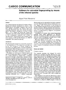
Figure 1. An example of DSSS modulation and demodulation: (a) The original signal is sk = {1, 2, 1}(k = 1, 2, 3) and the modulation function undergo amplitude modulation at 2 cycles/Tb . The signal is spread by an MLS spreading code S of length L = 31. (b) The spread signal M2′ is received after adding Gaussian noise N (0, 1). The despread signal D is obtained by multiplying S. The demodulated signal s′k is obtained by calculating the amplitude at 2 cycles/Tb . (c) The signal without DSSS is received after adding the same Gaussian noise, and demodulated by calculating the amplitude. (d) The power spectrum of D for k = 1 has a peak at 2 cycles/Tb , whereas the power spectrum of M2′ is distributed to various frequencies. The peak is larger than that of the signal received without DSSS.
ulation is that the power density of noise is reduced by spreading the noise to wideband when the signal is demodulated.
3.1. Overview of direct-sequence spread spectrum DSSS modulates narrowband signal to wideband signal by multiplying the original signal by the spreading code. Let Tb be the duration assigned to a cycle of the original signal, and sk (kTb ≤ tk < (k + 1)Tb ) a signal transmitted at time step k. The first step of DSSS modulates the signal transmitted by a radio wave or light to the modulated signal M1 (tk ) using a function F as follows: M1 (tk ) = F (sk ) (1) Any function can be allowed as F . Typical functions are amplitude modulation (AM) and binary phase shift keying (BPSK). Next, the modulated signal M1 is divided into L chips at time step k, and transmitted after spreading by a spreading code S as follows. M2 (tk ) = S(tk − kTb ) ◦ M1 (tk ) (2) where the operator ◦ signifies an entrywise product. Each chip of the signal is multiplied by the spreading code S of length L. Tc = Tb /L is the chip duration. The transmitted signal is received after adding noise. M2′ (tk ) = M2 (tk ) + n(tk ), (3) where n(tk ) is the noise including external light sources. Next, the received signal M2′ (tk ) is despread by multiplying it by a despreading code S ′ . D(tk ) = S ′ (tk − kTb ) ◦ M2′ (tk ) (4) ′ Finally, the demodulated signal sk is obtained by demodulating function F ′ corresponding to F from the despread signal D(tk ). s′k = F ′ (D(tk )) (5)
3.2. Spreading code by pseudo-noise sequence A maximal-length sequence (MLS) [2], which is a pseudo-noise (PN) sequence, is used as a spreading code that transform narrowband signal to wideband signal. MLS is a binary sequence generated using linear feedback shift register (LFSR). If a LFSR of length N is used, the length of MLS becomes L = 2N − 1. If it is expressed by bipolar code, an example of MLS is {1, −1, −1, 1, 1, 1, −1} for N = 3. A circular-shifted sequence of MLS is also a type of MLS. As the correlation between circular-shifted sequences is small, the signals spread by different MLSs do not interfere with each other, which is the characteristic utilized by CDMA. Fig.1 shows an example of DSSS modulation and demodulation. In (a), the original signal is sk = {1, 2, 1}(k = 1, 2, 3) and the modulation function is subjected to amplitude modulation at 2 cycles/Tb . The signal is spread by MLS spreading code S of length N = 5. In (b), the spread signal M2′ is received after adding Gaussian noise N (0, 1). The despread signal D is calculated by multiplying S. The demodulated signal s′k is obtained by calculating the amplitude at 2 cycles/Tb . In (c), the signal without DSSS received after adding the same Gaussian noise is shown, which is a narrowband approach. It is demodulated by calculating the amplitude in the same manner. In (d), the power spectrum of D for k = 1 has a peak at 2 cycles/Tb , whereas the power spectrum of M2′ is distributed to various frequencies, since the power of noise is spread by DSSS to wideband. The peak is larger than that of the signal received without DSSS. The mean-square error (MSE) of the demodulated signal with DSSS is 0.014, whereas that without DSSS is 0.033. The SNR is improved by 38% in this case by DSSS modulation compared to the narrowband approach. Compared to single sampling, the theoretical processing gain obtained by DSSS is Tb /Tc (= L) [5].
5099
3.3. Spatio-temporal filtering in demodulation for moving objects
0.08
-pass filter With high-pass filter Without high
0.06
Although the external light can be assumed to be the DC component of the signal when a static scene is being observed, it is not constant for the observation of dynamic scenes. If a spreading code has a sufficiently high frame rate, the change in brightness caused by the motion of an object is slow, and it is assumed that the motion only affects the low-frequency component. Therefore, the proposed method applies a high-pass filter to the received signal, and demodulates the signal after removing the lowfrequency component. A high-pass filter that passes signals with a frequency higher than frequency ωT (cycle/frame) is expressed in the frequency domain: { 1 ω > ωT (6) H(ω) = 0 otherwise The filter h(t) in the time domain is defined as follows. h(t) = w(t) ◦ IDFT(H(ω)), (7) where IDFT(H) is the inverse discrete Fourier transform of H(ω), and w(t) is the Hanning window function defined by w(t) = 0.5−0.5 cos(2πt/Lw ), where Lw is the window length. If the noise n(t) only has low-frequency component, the convolution with h(t) is h(t) ∗ n(t) = 0. The effect of external light is removed by the convolution of the received signal M2′ (t) and the high-pass filter h(t). Although the despreading code is S ′ (t) = S(t) for the spreading code based on MLS, the despreading code is given as follows, if a moving object is observed and the low-frequency component is not zero. D(t) = S ′ (t) ◦ M2′ (t) = S(t) ◦ (h(t) ∗ (M2 (t) + n(t)) = S(t) ◦ (h(t) ∗ M2 (t)) (8) The spread signal, however, also has non-zero lowfrequency component. As the signal despread by the above function is affected by the high-pass filter, the demodulating function F ′ needs to be modified according to the modulation function F . Additional noise filtering is achieved by combining spatial filtering. By assuming that neighboring pixels receive similar signals, spatial Gaussian filtering g(x, y) is applied to the received signal, where (x, y) is the coordinate of the pixel. The despreading function D is modified as follows. D(t, x, y) = S(t) ◦ (h(t) ∗ g(x, y) ∗ M2′ (t, x, y)) (9) The standard deviation σ of the Gaussian is σ = 1 (pixel) for all experiments described in this paper.
Filter value
0.04 0.02 0.00 −0.02 −0.04 −0.06 −0.08
0
5
10
15
20
Frames
25
30
35
40
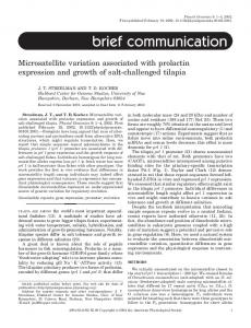
Figure 2. Example of the filter function generated from the coefficient of Eq.(12) in the case of L = 31, Lw = 8, and ωT = 1/Lw . The high-pass filter removes the low frequency component from the coefficients without high-pass filter.
3.4. Demodulation with amplitude modulation at DC component In this section, the case of amplitude modulation at the DC component is considered as a simple case of the modulating function F . Namely, M1 (tk ) = sk for kTb ≤ tk < (k + 1)Tb . Multiplexed illumination [15, 16, 8] can be considered as one of these cases. First, the case of single illuminant is considered. Let s be the transmitted signal for kTb − (Lw − 1) ≤ tk < (k + 1)Tb , and let m be the vector of the received signals M2′ (t), which is assumed after applying the spatial filter, and the vector S = [S(t)](t = ikTb /L, i = 0, . . . , L − 1) from the spreading code. By using the row vector h that consists of the high-pass filter values, the L × (L + Lw − 1) matrix H is definedas follows. h 0 ... 0 0 0 h 0 . . . 0 H= (10) ... 0 ... 0 0 h By removing the non-zero low-frequency component of noise by using the high-pass filter, the following equation holds. HSs = Hm (11) The least-square solution of this equation is given by s = (S T H T HS)−1 S T H T Hm. (12) The coefficient on the right-hand side of the equation corresponds to the composite function of despreading and demodulation, which is used as the filter to convolve with the received signal for demodulation. Fig.2 is an example of the filter function generated from the coefficient in the case of L = 31, Lw = 8, and ωT = 1/Lw . The high-pass filter removes the low frequency component from the coefficients without high-pass filter.
5100
Pattern off
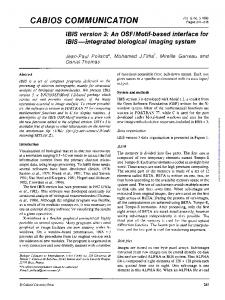
Figure 3. Experimental system consisting of a high-speed camera and a laser pattern projector. A 400-W lamp placed in close proximity was used as an external light to illuminate the target object.
Pattern on
Difference
No external light
Figure 4. The two images on the left are captured while the object is illuminated by the lamp. The laser pattern is turned off in the leftmost image, and turned on in the second image from the left. The third image is their differnece. The image on the right is captured without the lamp.
In the case of multiple illuminants, the individual signal is extracted by using spreading codes that are circularshifted from a code given by MLS. Let S j the column vector of the spreading code given by circular-shifting S for j times. If M illuminants are used, the coefficient matrix is obtained as follows similarly to the case of a single illuminant. (QT H T HQ)−1 QT H T H, (13) where Q is the matrix of spreading codes as follows. [ ] Q = S j1 S j2 . . . S jM (14)
Reference
L = 15
4. Applications
4.1. Structured-light system The first application is a structured-light system. A camera receives the signal, which is transmitted from a projector, and which is projected onto the surface of object. Structured-light methods can be classified into spatial and temporal encoding methods [14]. As the methods based on spatial encoding use a single image to find correspondence between the projector and camera, temporal information can be used to improve the SNR of the structured-light system during exposure to strong external light. In this paper, we apply the proposed method to one of spatial encoding methods that project wave-grid pattern [13]. A laser pattern projector, which is capable of blinking at a high frame rate, has been developed for the method [12]. Fig.3 shows the experimental system used in this research. In this experiment, the camera captures 12-bit images of 512 × 512 pixels at 22,500 frame/second (FPS). The laser pattern projector emits a wave-grid pattern formed by diffractive optical element (DOE) without scanning the laser direction. The wavelength of the laser is 808nm and the camera is equipped with an optical bandpass filter for the wavelength. First, we evaluate the robustness of the proposed method against the external light by changing the length of the spreading code. A 400-W lamp is used as an external light to illuminate the target object. The distance between the lamp and the target is approximately 0.7m and the illumi-
L = 63 L = 255 Figure 5. The top-left image is the reference image with which to compare images that are captured with long exposure time without external light. The other images are the results of demodulation with L = 15, 63, 255.
nance by the lamp is approximately 100K lx. The distance between the laser projector and the target is about 1.7m. The power of the laser is 40mW for this experiment. Fig.4 shows examples of the input images. The two images on the left are captured while the object is illuminated by the lamp. Although the laser pattern is turned on in the second image from the left, it is difficult to recognize the pattern. The third image is their difference. The image on the right is captured without the lamp. As the pattern by the laser is weak, the captured image is noisy even without the external light. We test the proposed method for spreading codes of length L = 7, 15, 31, 63, 127, 255, which correspond to the LFSR of length N = 3, . . . , 8. The parameters of the highpass filter are Lw = 8 and ωT = 1/Lw . Spatial filtering is not applied in the experiments of the structured-light system. As the power of the laser is constant while turned on,
5101
Peak Signal-to-Noise Ratio (dB)
37 36
(a)
35 34 33 32
(b)
31 30 29
7
15
31
63
127
Spreading code length L
255
Figure 6. The PSNRs of demodulated images of the wave-grid pattern are evaluated by comparison to the reference image.
the modulation is amplitude modulation at the DC component. Fig.5 shows the results of demodulation. The top-left image is the reference image for comparison with images that are captured with a long exposure time without external light. The other images are the results of demodulation with L = 15, 63, 255. Although the pattern in the input images is almost impossible to recognize, the proposed method succeeded in demodulating the pattern. The demodulated images are evaluated by comparison to the reference image. The peak signal-to-noise ratio (PSNR) for the results is shown in Fig.6. The PSNR is improved according to the length of the spreading code (= 2N − 1), which is almost linear to the length of the LFSR N . Next, we test the system to observe a moving object exposed to sunlight. Fig.7 shows images in which a bouncing ball is observed. The illuminance of the sunlight is approximately 50K lx. The images in row (a) show three moments during a bounce. The images in row (b) are the input images when the laser is turned on. Although the laser power is 85mW in this experiment, it is almost impossible to recognize the pattern. The length of the spreading code is L = 255. The results of demodulation without filtering are shown in row (c). Artifacts occur around the boundary of the ball and hand caused by the motion. The results with temporal filtering are shown in row (d). The artifacts caused by motion are successfully removed from the demodulated images. The 3D reconstruction in row (e) is generated for each demodulated image by the method of [13].
4.2. Photometric stereo The second application is photometric stereo [17]. The method illuminates an object from various direction and estimate the normal direction for each pixel from the intensity between different illuminations. The depth map is calculated by integrating the normal vectors. The basic method involving the use of photometric stereo is the time-division
(c)
(d)
(e)
Figure 7. The images in row (a) show three moments at which the ball bounces. The images in row (b) are the input images when the laser is turned on. The results of demodulation without filtering are shown in row (c). The results with temporal filtering are shown in row (d). The 3D reconstruction in row (e) is generated for each demodulated image by the method of [13].
Figure 8. The experimental system for photometric stereo measurements has 60 LEDs mounted around the camera lens. Six neighboring LEDs are turned on/off as a set, and the target object is illuminated from ten directions. The distance between the camera and the object is approximately 1.5m.
approach in which lights are turned on in a specific order. Contrary to this, the proposed method illuminates an object based on multiplexed illumination of multiple lights during exposure to external light.
5102
(a)
Figure 9. Three examples of input images captured for photometric stereo by multiplexed illumination under room light.
Fig.8 shows the experimental system for photometric stereo. Sixty LEDs are mounted around the camera lens. Six neighboring LEDs are turned on/off as a set, and the target object is illuminated from ten directions. Image acquisition is synchronized to LEDs that blink at 1000FPS. The length of the spreading code is L = 127. The distance between the camera and the object is approximately 1.5m. The illuminance at position of the object is about 6lx by six LEDs, and 25lx when the system illuminates based on the spread spectrum modulation. The external light is 600lx when ambient room light is used. Fig.9 shows three examples of the input images. As the power of the LEDs is very weak compared to the room light, the difference in illumination is difficult to recognize from a single image. Fig.10 shows the results of the proposed method. The images on the left and in the middle are the input images for photometric stereo. Row (a) shows the reference images captured by long exposure time for each LED set without external light. In rows (b)-(d), the images are generated by demodulation. The images on the right are the results of 3D reconstruction. The implementation of photometric stereo used in the experiment is simple by assuming Lambertian surface and orthographic model for the camera and LED lights. As the assumption does not completely correspond to the actual setup, the reconstructed shape is distorted by Euclidean reconstruction. Row (b) shows the images captured by multiplexed illumination without external light. In rows (c) and (d), the images are captured by multiplexed illumination under external light. The demodulated images are generated with temporal filtering in (c) and spatio-temporal filtering in (d). The PSNRs of the demodulated images are (b) 30.37dB, (c) 24.21dB, and (d) 30.21dB. Although the noise remains in the demodulated images, the 3D shape can be reconstructed by photometric stereo even under the external light, and the result is improved by spatio-temporal filtering. Next, we test the use of photometric stereo for a moving object by rotating it on a turntable. Fig.11 shows the result of the proposed method. In the case of multiple illuminants, the spreading codes are obtained by circular shift of the original code. If the shift count of neighboring LEDs is continuous, the same light pattern occurs sequentially, which increases the low-frequency component and the demodulation with temporal filtering fails as shown in (a). Therefore, we use circular-shifted codes S ji in Eq.(14) with
(b)
(c)
(d)
Figure 10. The images on the left and in the middle are the input images for photometric stereo. Row (a) shows the reference images captured by using a long exposure time for each LED set without external light. In rows (b)-(d), the images are generated by demodulation. The images on the right are the results of 3D reconstruction. Row (b) shows images captured by multiplexed illumination without external light. In rows (c) and (d), the images are captured by multiplexed illumination under external light.
(a) (b) (c) Figure 11. In the case of multiple illuminants, if the shift count of neighboring LEDs is continuous, the demodulation with temporal filtering fails as shown in (a). Therefore, we use circular-shifted codes with every fourth shift count. The result without filtering is shown in (b). The proposed method with spatio-temporal filtering succeeded to demodulate the image without causing artifacts around the boundary as shown in (c).
every fourth ji = 4i(i = 0, . . . , M ). The result without filtering is shown in (b). The artifacts occurs at the boundary even if the motion is slow. The proposed method with spatio-temporal filtering succeeded in demodulating the image without causing artifacts as shown in (c). The parameters of the high-pass filter are Lw = 8 and ωT = 1/Lw .
5103
(a) (b) (c) (d) Figure 12. (a) one of the input images. (b) the hidden image. (c) a frame of the signal for the hidden image if no visible image is added. (d) the result of demodulation with spatio-temporal filtering.
4.3. Image embedding by illuminant-camera system The third application is image embedding by the illuminant-camera system. In this paper, we use a PC monitor as an illuminant. When the monitor displays a video, this adds a low-power signal to the video. The light modulated by the proposed method can be high frequency and low energy, and the embedded signal is difficult to recognize by the human eye. The proposed method superimposes signals detected only by a camera on video visible to the human eye. The refresh rate of the monitor used in this experiment is 60Hz, which is much slower than that in the other experiments. Therefore, we test a simple experiment that hides an image and shows another image simultaneously. If a hidden image is modulated at the DC component, it is easy to detect by the human eye. Therefore, the modulation function is amplitude modulation at 6 cycles/Tb , the length of the spreading code is L = 31. The proposed method changes the phase of the carrier wave spatially so that the signal for the hidden image is difficult to recognize. The intensity of each pixel of the PC monitor is Iv + Ih , where Iv is the intensity of the visible image, and Ih is the signal for hidden image. In this experiment, the range of Iv and Ih are 0 < Iv ≤ 150 and −10 < Ih ≤ 10. The demodulated image is calculated by the amplitude at the frequency of the carrier wave. Since the frequency is higher than the threshold ωT = 1/8 of the high-pass filter, we assume it is not affected by temporal filtering. Fig.12 shows the images of image embedding. (a) is one of the input images. The image of baboon face is visible for human eye. (b) is the hidden image “Lena” embedded by the proposed method. (c) is the signal for the hidden image if no visible image is added. (d) is the result of demodulation with spatio-temporal filtering. The PSNR of the result is 28.05dB. Although the amplitude of the hidden image is less than 10% of the visible image, it is demodulated from the unrecognizable signal.
4.4. Discussion The proposed method has two limitations. First, both the signal of illuminants and the external light must be within the dynamic range of the camera. If the pixels are satu-
rated by the external light, or if the signal is too weak to be detected after AD conversion of the imaging sensor, the method does not work. Second, the method assumes that the frequency of the signal can be discriminated from the brightness change caused by motion or other changes of illumination. If the motion is relatively fast compared to the frame rate, this assumption does not hold. The high-pass filtering does not work in such cases. Additionally, capturing multiple images can be regarded as long exposure time for a demodulated image. In the experiment in Fig.7, as a demodulated image is reconstructed from L + Lw − 1 images, the exposure time can be regarded as 11.6ms (= 262/22500 s). Motion blur occurs in the demodulated images due to the long exposure time to observe the bouncing ball. In spite of the motion blur, the 3D reconstruction has succeeded in the experiment.
5. Conclusion In this paper, we proposed a method of energy-efficient active illumination in an environment with intensive external lights. We built a system consisting of light sources and cameras and named illuminant-camera system. The proposed method was used to solve problems of illuminantcamera systems based on spatio-temporal signal processing of optical communication between illuminants and cameras. The signal transmitted from the illuminants was modulated based on DSSS, and the modulated signal can be demodulated even if the signal is captured with intensive external lights. We tested the proposed method for three applications: a structured-light system, photometric stereo, and image embedding. We showed that images of moving objects can be demodulated in combination with a spatiotemporal filter. In future, we plan to use the illuminantcamera system to solve various problems. For example, the proposed method could be applied to the problem of multiplexed illumination at different wavelengths as tackled in [11]. Additionally, other devices such as digital mirror devices (DMD) can be used to construct a flexible system that can be applied to various problems.
5104
References [1] S. Chen and C. Chow. Differential signaling spread-spectrum modulation of the led visible light wireless communications using a mobile-phone camera. Optics Communications, 336:240–242, 2015. [2] S. Golomb and G. Gong. Signal Design for Good Correlation: For Wireless Communication, Cryptography, and Radar. Cambridge University Press, 2005. [3] M. Gupta, Q. Yin, and S. Nayar. Structured light in sunlight. In Proc. IEEE International Conference on Computer Vision (ICCV), 2013. [4] M. Harwit and N. J. Sloane. Hadamard transform optics. Academic Press, 1979. [5] S. Haykin. Communication systems, chapter 7. John Wiley & Sons, 4th edition, 2008. [6] N. Lourenc¸o, D. Terra, N. Kumar, L. Alves, and R. Aguiar. Visible light communication system for outdoor applications. In Proc. 8th International Symposium on Communication Systems, Networks & Digital Signal Processing, 2012. [7] L. Marvel, C. Boncelet, and C. T. Retter. Spread spectrum image steganography. IEEE Transactions on Image Processing, 8(8):1075–1083, 1999. [8] Y. Mukaigawa, K.Sumino, and Y.Yagi. Multiplexed illumination for measuring brdf using an ellipsoidal mirror and a projector. In Proc. of Asian Conference on Computer Vision, volume LNCS-4844, pages 246–257, 2007. [9] T. O’Farrell and M. Kiatweerasakul. Performance of a spread spectrum infrared transmission system under ambient light interference. In Proc. The Ninth IEEE International Symposium Personal, Indoor and Mobile Radio Communications, 1998. [10] M. O’Toole, S. Achar, S. Narasimhan, and K. Kutulakos. Homogeneous codes for energy-efficient illumination and imaging. In Proc. ACM SIGGRAPH, 2015. [11] J. Park, M. Lee, M. D. Grossberg, and S. K. Nayar. Multispectral imaging using multiplexed illumination. In IEEE International Conference on Computer Vision, 2007. [12] R. Sagawa, T. Kawamura, R. Furukawa, H. Kawasaki, and Y. Matsumoto. One-shot 3d reconstruction of moving objects by projecting wave grid pattern with diffractive optical element. In Proc. 11th IMEKO Symposium Laser Metrology for Precision Measurement and Inspection in Industry, 2014. [13] R. Sagawa, K. Sakashita, N. Kasuya, H. Kawasaki, R. Furukawa, and Y. Yagi. Grid-based active stereo with singlecolored wave pattern for dense one-shot 3d scan. In Proc. 2012 Second Joint 3DIM/3DPVT Conference, pages 363– 370, 2012. [14] J. Salvi, J. Pages, and J. Batlle. Pattern codification strategies in structured light systems. Pattern Recognition, 37(4):827– 849, 4 2004. [15] Y. Schechner, S. Nayar, and P. Belhumeur. A theory of multiplexed illumination. In IEEE International Conference on Computer Vision, volume 2, pages 808–815, 2003. [16] A. Wenger, A. Gardner, C. Tchou, J. Unger, T. Hawkins, and P. Debevec. Performance relighting and reflectance transformation with time-multiplexed illumination. In SIGGRAPH, 2005.
[17] R. Woodham. Photometric method for determining surface orientation from multiple images. Opt. Eng., 19(1):139–144, 1980.
5105