Programming and Computer Software, Vol. 31, No. 5, 2005, pp. 282–291. Translated from Programmirovanie, Vol. 31, No. 5, 2005. Original Russian Text Copyright © 2005 by Barladyan, Voloboi, V’yukova, Galaktionov, Deryabin.
Illumination Modeling and Generation of Realistic Images Using Internet Technologies B. Kh. Barladyan*, A. G. Voloboi*, N. I. V’yukova**, V. A. Galaktionov*, and N. B. Deryabin* *Keldysh Institute of Applied Mathematics, Russian Academy of Sciences, Miusskaya pl. 4, Moscow, 125047 Russia **Institute of System Studies, Russian Academy of Sciences, Nakhimovskii pr. 36, korp. 1, Moscow, 117218 Russia e:mail:
[email protected] Received October 7, 2004
Abstract—A technology for developing Internet applications involving computer graphics is presented. Such applications enable Internet users create physically accurate models of global scene illumination and produce high-quality images; it also allows scene editing. Based on this technology, software for creating active presentations or services accessed via the Internet was developed. Architectural, technological, and software solutions that ensure effective modeling of illumination, produce realistic images, and ensure a reasonable response time when working with Internet applications are considered.
1. INTRODUCTION Currently, many goods, products, and technologies are presented at Internet sites. As a rule, such sites include not only textual information but also images and multimedia data that help demonstrate properties that are difficult to represent in verbal form (style, aesthetic and ergonomic properties, etc.). For example, site [1] presents various makes of Jaguar cars. The visitor may rotate images thus looking at the car from different viewpoints, open and close flap doors of cabriolets, and so on. Site [2] represents various makes of Honda cars. Here, visitors also can look through images and animations that present differently colored cars with various variants of interior design. An example of the presentation from a different domain can be found at site [3], where the capabilities of the Virtual Reality Design Lab concerning the lighting design of stage performances are shown. The images presented at this site were generated by modeling the illumination for scenes that represent real-life theaters with corresponding decors under given lighting conditions. The modeling was based on the Radiance software [4]. In the presentations indicated above and in other similar presentations on the Internet, pre-stored highquality images are used. Obviously, presentations could be made more informative and attractive if they could dynamically generate images for the lighting conditions, environment and the background scenes specified by the user, as well as for various options of the exterior or interior design of products, etc. The technology discussed in this paper aims at solving this problem. On the basis of this technology, software was developed for creating Internet computer
graphics applications that can generate realistic images using physically accurate simulation of illumination and enables the user to do some editing of the scenes. The software called LKernel (Lighting Kernel) was developed in the Computer Graphics Department of the Keldysh Institute of Applied Mathematics, Russian Academy of Sciences. Applications developed on the basis of this software make it possible to create active Internet presentations where the site visitor can choose various visualization options and model the scene, while the required images are generated during the Internet session. A natural application of this software is the development of Internet services for designing indoor scenes and lighting. A high quality of the resulting images, which is a key requirement for such kind of software, can be achieved only by physically accurate modeling of light propagation. To obtain high-quality realistic images, a high degree of accuracy and detail in the description of the geometry, light sources, and optical properties of the materials used in the scenes is very important. This approach is computationally costly. At the same time, access through the Internet must have reasonable response time; therefore, the computations must be fast. These two contradicting goals are difficult to achieve. The corresponding architectural, algorithmic, and software solutions and their implementation are considered in this paper. The paper is organized as follows. Section 2 is devoted to the basic solutions concerning the architecture of computer graphics applications that perform interactive physically accurate computations of illumination and to the interaction between the client-end and server-end components. An overview of the algorithms
0361-7688/05/3105-0282 © 2005 Pleiades Publishing, Inc.
ILLUMINATION MODELING AND GENERATION OF REALISTIC IMAGES
User interface programs
283
Server program LKernel
I
Requests
N T Requests Images, parameters, cameras, etc.
E
Images, parameters, cameras, etc.
R N Computation of illumination and image generation
E T
Libraries of scenes and objects Data concerning the user sessions
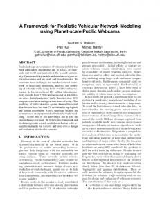
Fig. 1. Organization of an Internet application for the interactive physically accurate illumination modeling: interaction of the user interface components with the server component.
and technologies used in the software being discussed is also given. In Section 3, the functional capabilities of the software are considered. In Section 4, we describe the interface through which the client-end components interact with the server-end components. In Section 5, we discuss the techniques used to speed up the computations (namely, we discuss the optimization of the algorithm used to model the global illumination) and the techniques used for the parallelization of computations in illumination modeling and image generation. In Section 6, administrative tools and scene libraries are briefly described. In conclusion, we discuss the results of the work and consider the prospects of future development. 2. BASIC SOLUTIONS USED IN THE INTERNET APPLICATION 2.1. Architecture of Internet Applications for Interactive Physically Accurate Illumination Modeling In the framework of our model, the computer graphics application for interactive illumination modeling runs in a distributed environment that includes the user computer and the Web server that renders the application.1 The performance of the application considerably 1 Several
computers can be involved in the computations on the server end (See Section 5). PROGRAMMING AND COMPUTER SOFTWARE
Vol. 31
depends on the solutions concerning the distribution of the computations among computers and on the organization of the interaction between the components running on these computers. In order to service as many users as possible, one must take into account that the user’s computer can be not very powerful and the network not very fast. For this reason, we decided to perform resource-hungry computations concerning the modeling of illumination and image generation on the server end. The server also stores the scene descriptions, which can include hundreds of thousands and even millions of objects. One more argument in favor of this decision is the protection of data describing the scenes. Indeed, to produce high-quality images, the geometry of the scene must be described with a high degree of detail and the properties of surfaces and of light sources must be carefully chosen (or even measured). Designing such scenes can take weeks of work of highly skilled personnel. Usually, such data are somebody’s property. From this point of view, it is important that detailed scene descriptions remain on the server. The architecture of an Internet application for interactive physically accurate illumination modeling and of the organization of the interaction between its components is schematically presented in Fig. 1. This architecture was implemented in the LKernel software. The user’s computer runs a program that implements the graphical interface functions and scene renNo. 5
2005
284
BARLADYAN et al.
dering. To edit scenes, model illumination, and generate images, this program sends requests to the component running on the server. The server component returns the structures and images from scene libraries, editing results, current settings of the camera, and so on. The server component supports the concurrent work of multiple users and handles the data of multiple open sessions. 2.2. Main Algorithmic Solutions Physically accurate modeling of illumination requires that both the primary and secondary illumination, which is a result of multiple light reflections, be taken into account. The secondary illumination is also called global. The primary illumination is calculated using the deterministic ray tracing method [5]. All physically valid methods for the computation of global illumination are based on the approximate solution of the so-called rendering equation [6]. The difficulty in solving this equation is due to its recursive nature and the complexity of the integration domain. Therefore, this equation is solved by various numerical methods. In the software discussed in this paper, the rendering equation is solved using the Monte Carlo method for the forward ray tracing [7]. The idea behind this method is a static simulation of the mechanism of light propagation by modeling all possible ray trajectories. The trajectories of photons are traced from the moment when they are generated by a light source to the moment when they are absorbed or leave the scene of interest. The direction in which a photon is emitted, wavelength, and the starting point on the light source are determined randomly using the photometric distribution of energy of the light source and its geometry. The photon trajectory up to the intersection with a surface is traced, and the subsequent behavior of the photon depends on the properties of this surface. The method naturally can deal with all types of surfaces including combinations of diffusive and specular properties, as well as the surfaces described by complex reflection (or refraction) functions. These functions make it possible to model such fine optical phenomena as the caustic effect, i.e., light spots that occur due to focusing of light energy by perfectly refracting materials. The method is independent of the camera position, and it does not imply the generation of an image; it only supplies information of the global illumination, which can be used for visualization and image generation later on. 2.3. The Technological Base of the Software The software discussed in this paper is based on the Component Object Model (COM) developed by Microsoft [8]. The idea behind this approach is that applications can be created using components; this is similar to how an architect designs a building using
standard constructions. Both ready-to-use components and the components developed for the particular application can be used. The interaction between the application and a component is completely determined by the formal specification of the component’s interfaces; it is independent of its location in the distributed computer system, of the programming language in which the component was implemented, and of all other factors not described in the specification. The components can interact both within the same process and operate as separate processes that may run on different computers in a network. The component approach helps solve such problems as scalability, integrability, application fault tolerance; it also reduces the development and maintenance costs. The main part of LKernel is the server component that models the illumination, generates images, provides means for scene editing, and so on. The software also includes administrative tools, which are discussed in Section 6. The components implementing the user interface of applications can be developed by independent developers using the formal specification of the server component’s interface, which is discussed in Section 4. The applications' user interface is designed and implemented in accordance with the needs of the company whose products are presented at the site and on the general design of the site. 3. CAPABILITIES OF THE SOFTWARE FROM THE END-USER POINT OF VIEW Consider the functionality of the software using a typical scenario of a working session. A. Scene loading. The user looks through the contents of the scene library represented by icons, then selects and loads one of them. There are two types of scenes—fixed and parametric. A fixed scene can have arbitrarily complex geometry; usually, these are indoor scenes. Such scenes are prepared using some threedimensional modeling system and then imported into the illumination modeling system. An example of a fixed scene is shown in Fig. 2a. A parametric scene is a prism-shaped room in which the floor and the ceiling are polygons, and the walls are rectangles of the same height. An example of a parametric scene is shown in Fig. 2b. At every moment, only a single scene can be loaded; when a new scene is loaded, the work with the previously loaded scene becomes impossible. The scene description is loaded on the server that provides Internet services. The user’s computer receives only scene images generated according to the user’s actions. B. Editing parametric scenes. After loading a parametric scene, the user can change its shape, namely, add, delete, and move the vertices of the polygon that forms the floor (ceiling) of the room, change the walls height, and specify optical properties (color, reflection coefficient) for each internal surface of the
PROGRAMMING AND COMPUTER SOFTWARE
Vol. 31
No. 5
2005
ILLUMINATION MODELING AND GENERATION OF REALISTIC IMAGES
285
(a) A
O1
B
O2
C F O3
O4 D
O5
(b)
O6 E
Fig. 2. (a) Example of a fixed scene; (b) example of a parametric scene.
room. For parametric scenes, the concept of the “working plane” is defined; the working plane is specified by the user. The working plane is a virtual surface placed by the user at a certain height; this surface does not affect the modeling: is used to visualize the illumination distribution at the specified level. For fixed scenes, this option is not supported. C. Working with the library of objects and light sources. The library of objects and light sources (for brevity, it is called the object library below) contains elements that represent the following objects: • furniture (geometric objects with given optical properties of their surfaces), PROGRAMMING AND COMPUTER SOFTWARE
Vol. 31
• lighting devices such as chandeliers, standard lamps, and the like (objects that have both geometrical and lighting properties), • pure light sources. The system supports several types of light sources: point, conical, parallel, and elongated (linear, circular, and rectangular) sources, as well as light sources specified in the standard IESNA format [9] with given angular distribution of intensity. The user can add elements from the object library to fixed and parametric scenes, choose a location for them in the scene, and delete them. All light sources of a certain type in the scene can be replaced by light sources of another type by a special operation. No. 5
2005
286
BARLADYAN et al.
Libraries: getting information on the contents Sessions: opening, closing
Scenes: loading, unloading
Geometry: getting parameters, changing
Objects: editing
Server component LKernel
Optical properties: getting information; changing Light sources: getting information
Images: generation of images, panoramic views, level lines, etc. Computation of the illumination
Camera: getting and changing the parameters
Fig. 3. Server component interface: main groups of services.
D. Computation of global illumination. After editing the scene as desired, the user starts the computation of the global illumination by the Monte Carlo ray tracing method. As a result, an illumination map is formed and dynamically presented to the user during the calculation. The quality (accuracy) of the map depends on the number of ray trajectories traced. The user can specify a desired accuracy in advance or just stop the computations when the current map becomes satisfactory. E. Examination of the illumination distribution. The distribution of illumination can be visually represented using color filling. For parametric scenes, level curves can be drawn on each of the surfaces (floor, ceiling, walls, and the working plane). Using these tools, the user can evaluate the quality of the illumination. On the basis of these results and the visual estimate of the scene, the user can add more light sources, change the position of some objects in the scene, and so on. Thus, repeating steps C through E, the site visitor can design lighting in the selected indoor scene. When the result is satisfactory, the user can proceed to the generation of high-quality images for presentations. F. Generation of images and panoramic views. The last stage of working with a scene is generation of high-quality images for various positions of the camera and generation of panoramic views in the Quick Time format [10]. Images are generated using backward ray tracing and precalculated illumination maps. This makes it possible to model a wide range of optical phenomena, such as diffusive multiple reflection of light, color transfer, specular reflection, and caustic effect. The user can control the quality of the resulting images. Low- and medium-quality images are gener-
ated quickly, and the generation of high-quality images can take considerable time. 4. SOFTWARE INTERFACE When the development of LKernel started, the Computer Graphics Department of the Institute of Applied Mathematics already had a considerable reserve of software implementing the functions indicated in the preceding section and used in other computer graphics applications [11]. In the framework of the LKernel project, we had to represent some fragments of that software as a COM object so that independent developers could use it for developing interactive computer graphics applications including Internet applications. The main thing in this work was designing a simple but powerful interface that could be used to develop meaningful applications including applications with the access via the Internet. The implementation of these specific features required that the existing code be revised, in particular, to make the services of the server component reenterable; otherwise, it would be difficult to implement the work with multiple sessions. Both in the interface design and in the implementation of the methods, it was important to find solutions that ensure a quick response to users' requests. The server component (kernel) of the software has a unified interface; its main services are discussed in this section. An overview of the kernel services is presented in Fig. 3. Sessions The server component interface assumes a certain discipline of access to the services. All manipulations with scenes are performed within a session. Accord-
PROGRAMMING AND COMPUTER SOFTWARE
Vol. 31
No. 5
2005
ILLUMINATION MODELING AND GENERATION OF REALISTIC IMAGES
ingly, there are methods for opening and closing a session. When a session is opened, the session identifier is returned that is used as a parameter for all other services. The sessionwise organization makes it possible for an application to do anticipatory computations of the illumination when the user has not yet explicitly requested this computation. Certainly, anticipatory computations can be performed only when the available computer resources are not involved in other computations. The session discipline also ensures a more efficient use of memory. Simultaneously, several independent sessions can be executed. Libraries The kernel currently supports three libraries: a library of fixed scenes, a library of parametric scenes, and a library of objects. Two more services, given the identifier of an object, return the textual description of an object and its icon. Scenes For scenes, the loading and unloading services are available. It is possible to find out if the current scene is loaded, determine its identifier, find out whether it is parametric or fixed, and if it was changed since its loading. Scene Geometry Both for fixed and parametric scenes, the geometric data query service is supported. It returns the height and the number of the walls and the array containing the coordinates of vertices of the polygon at the base of the room. For parametric scenes, the change of geometry is supported. The corresponding service has all the parameters listed above as its input parameters. There is also a service that returns the units of measurement used to represent the geometric data; this service also enables one to change the units of measurement. Optical Properties of Surfaces (for Parametric Scenes) The services belonging to this group enable one to find out and set the optical properties (the reflection coefficient and the color) for all surfaces of the parametric scene. This service is not applicable to fixed scenes, because their optical properties are specified at their design. Object Editing The services of this group are used to find out which objects are present in the current scene and to change the set the objects. A description of an object (or a three-dimensional set of identical objects located at the nodes of a threedimensional regular grid with a constant step size in each of the coordinates) is represented in the form of a PROGRAMMING AND COMPUTER SOFTWARE
Vol. 31
287
structure containing the object’s coordinates with respect to the scene and three angular coordinates that specify the object’s orientation in space. The color and the intensity of the light sources within the object are specified. For sets of objects, the structure includes fields that specify the number of object instances and the step size in each of the directions. When information about scene objects is requested, the number of objects in the scene and an array of pointers to the structures describing these objects are returned. The same parameters are used as input parameters for setting objects in the scene. In the general case, the term object means a three-dimensional set of objects. Getting Information about Light Sources The methods of this group enable one to obtain data about the set of light sources in an object or in a scene and find out the individual characteristics of each source. The data about the set of light sources in an object or in a scene include the number of the sources and an array of pointers to the structures that describe the sources—their location, orientation, type, etc. For a source specified according to the IESNA standard, one can obtain detailed information about the source characteristics and an image of its goniometric diagram. Camera In each fixed and parametric scene registered in the library, there is the description of a camera, which is required to generate images of the scene. The methods of this group enable the application to get and set the parameters specifying the location, orientation, and the viewing angle of the camera. Computation of the Illumination This group includes two methods. One of them computes the illumination up to the specified accuracy. The other continues the computations until the specified accuracy is achieved or the specified time slice has elapsed. The value of the achieved accuracy is returned as an output parameter. Since the computations are incremental, the second method can be used to enable applications to dynamically show the current state of the computations and give the user the option to stop the computations when the visual estimate of the quality is satisfactory. Image Generation Services for generation scene images and panoramic views in the Quick Time format are supported. These services can produce images of the specified quality. A visual representation of the illumination distribution in No. 5
2005
288
BARLADYAN et al.
Table 1. Comparison of the computation time when using pseudorandom sequences (TMC) and quasi-random samples (TQMC) for the computation of global illumination by the Monte Carlo method Scene
Accuracy (%)
TMC
TQMC
Speedup (times)
Office Office Montage Montage Montage
97 98 97 98 99
332.164 757.918 54.202 135.731 972.882
224.057 486.441 32.624 70.717 243.072
1.48 1.56 1.66 1.92 4.00
the scene in the form of level curves and color filling can be also obtained. In addition, there are some auxiliary services for memory management, generating diagnostics, etc. 5. SPEEDING UP ILLUMINATION MODELING AND IMAGE GENERATION The computation of global illumination and generation of realistic images require large computational resources. On the other hand, long response time reduces the number of site visitors. Therefore, an efficient implementation of resource-hungry operations becomes critical in the framework of Internet applications. When the work on the project started, the deterministic ray tracing method for image generation had already been optimized. The implementation of this method uses an adaptive technique of decomposing the scene space into voxels (volume pixels) based on the algorithm suggested in [12]; algorithms for the interpolation of homogeneous regions of the image and other efficient programming techniques were also used. Therefore, the main difficulty in the project considered in this paper was the speedup of the computation of global illumination, which requires much more computational resources than the image generation based on ray tracing. 5.1. Methods for Speeding Up the Computation of Global Illumination The main cause of the great computational complexity of the global illumination computation is random noise inherent in all Monte Carlo algorithms. Since illumination is mainly a smooth function, we cannot get good images without getting rid of this noise. A conventional solution of this problem when the Monte Carlo algorithms are used with a pseudorandom sequence is that the computations are continued until a satisfactory result is obtained and the noise disappears. However, this approach is undesirable for Internet applications. Therefore, we replaced pseudorandom
sequences by quasi-random samples. An advantage of the quasi-Monte Carlo method is that the random noise is considerably smaller and the convergence rate is much higher under certain conditions. A detailed presentation of the quasi-Monte Carlo method as applied to the computation of the global illumination can be found in [13]. At early stages of the work on the project, we made some measurements to estimate the efficiency of some optimization methods and of their parallelization, which is discussed below. The results of these measurements are presented in this section. In these measurements, we used the scenes depicted in Figs. 4a and 4b. Table 1 presents the results that demonstrate the speedup achieved by using quasi-random samples rather than pseudorandom sequences in the computation of global illumination by the Monte Carlo method. The measurements were made for the scenes Office and Montage with various values of the resulting accuracy. The computation time is given in seconds. Another speedup method developed in the framework of the project is the elimination of the primary rays from the tracing performed by the Monte Carlo method. The primary rays tracing was replaced by the deterministic computation of the direct illumination. In the process, direct illumination maps are constructed that are later used both as a secondary light source for modeling by the Monte Carlo method and for scene visualization. As a result, the total time taken by image generation is reduced. The efficiency of this optimization technique significantly depends on the scene illumination. The speedup compared to the Monte Carlo method can be from several percent (e.g., 12% for the scene Office) to several times (e.g., 2.5 times for the scene Montage). 5.2. Parallel and Distributed Computations In addition to algorithmic methods, we used parallel computations in LKernel to speedup image generation and global illumination computation. Both horizontal parallelism, which is based on using clusters consisting of several computers, and vertical parallelism based on multithreaded computations, which effectively uses multiprocessor computers, were employed. The idea of the parallel implementation of the backward tracing algorithm used for image generation is based on the fact that the luminous intensity of individual pixels can be calculated independently of each other. The screen is adaptively decomposed into several nonoverlapping regions so as to balance the workload of the available processors. Each processor performs tracing for certain regions by executing the sequential version of the algorithm. The completed fragments are joined into the resulting image. The parallel implementation of the forward tracing algorithm in the computation of global illumination is based on the fact that each ray can be traced independently of the others. Note that
PROGRAMMING AND COMPUTER SOFTWARE
Vol. 31
No. 5
2005
ILLUMINATION MODELING AND GENERATION OF REALISTIC IMAGES
289
(a)
(b) Fig. 4. (a) Scene Office; (b) scene Montage.
in the earlier parallel implementations of both algorithms, only horizontal parallelism was used. More efficient multithreaded parallelism was implemened in the LKernel project. More detailed information about the parallelization methods used in LKernel can be found in [14, 15]. The measurements of the computation time needed to calculate global illumination using multiprocessor and cluster configurations showed that both PROGRAMMING AND COMPUTER SOFTWARE
Vol. 31
kinds of parallelism significantly speed up the computations and are scalable. Table 2 contains the results of measurements made to estimate the efficiency of multithreaded computations of global illumination. The measurements were performed on the four-processor server HP-900 with the processors Intel Pentium III Xeon operating at the clock rate of 900 MHz for the scenes Office and MonNo. 5
2005
290
BARLADYAN et al.
Table 2. The efficiency of multithreaded computations: N is the rate of ray tracing (in rays per second), E is the efficiency (the ratio of the computation speed to the number of processors normalized by the speed of one processor) Scene Office l1 Office l2 Montage l1 Montage l2
1 processor
2 processors
3 processors
4 processors
N
E
N
E
N
E
N
E
54653 59620 84935 90276
1.0 1.0 1.0 1.0
104696 108449 134537 166257
0.958 0.910 0.792 0.921
141600 151831 179807 226642
0.864 0.849 0.706 0.837
171608 190101 222297 278795
0.785 0.797 0.654 0.772
Table 3. The efficiency of distributed computations: T is the computation time needed to achieve a prescribed accuracy; E is the efficiency (the ratio of the computation time on a single computer to the computation time on a cluster normalized by the computational power of the cluster) Scene Office l1 Office l2 Montage l1 Montage l2
1
12
123
1234
T
E
T
E
T
E
T
E
182.54 153.72 105.86 18.22
1.0 1.0 1.0 1.0
95.30 81.78 55.52 9.34
0.75 0.74 0.75 0.76
67.11 54.35 35.33 6.36
0.66 0.69 0.73 0.70
47.50 43.91 28.33 5.31
0.70 0.64 0.68 0.62
tage under two different lighting conditions (called l1 and l2, respectively). The speed of computations was measured in the number of rays traced per second (N). The efficiency E of the multithreaded computations was measured as the ratio of the computation speed N to the number of processors normalized by the speed for the case of a single processor. It is seen from this table that the efficiency of the implementation of multithreaded computations is large for two processors and reduces as the number of processors increases. To improve the efficiency in the case of more than four processors, the implementation must be improved. However, this is presently not very important because computers with more than four processors are rare. We also examined the speedup of the computations when several computers were used in parallel. The results are presented in Table 3. The following computers were used: (1) dual Intel Pentium III 600 MHz, (2) dual Intel Pentium III 933 MHz, (3) dual Intel Pentium III 933 MHz, (4) dual AMD 1500 MP 1333 MHz. In these tests, we fixed the time T of achieving the prescribed accuracy for various clusters consisting of these computers. In Table 3, 1 means that only the first computer was used; 12 means that the first and the second computers were used; 123 means the cluster of the first, second, and third computers, and 1234 indicates the cluster consisting of all four computers. The efficiency coefficients E are calculated as the ratio of the computation time on a single computer to the computation time on the cluster normalized by the processing power of the cluster (i.e., by the sum of the
clock rates of all the processors). For convenience of the presentation, the efficiency of the first computer is assumed to be unity. The measurements used the scenes Office and Montage under the lighting conditions 11 and 12. The computations were performed until a prescribed accuracy was achieved. It is seen from Table 3 that the use of distributed configurations considerably reduces the computation time. However, the efficiency coefficients also show that there are some reserves for improving the implementation of the horizontal parallelism. 6. ADMINISTRATIVE TOOLS The end users working with applications based on LKernel via the Internet must not be allowed to modify and save libraries of scenes and objects. Neither have they the right to control the configuration of the cluster on the server end. It is assumed that these operations are done by experts that are responsible for the design of presentations and by the site administrator. To perform these functions, in addition to the LKernel kernel, we developed an administrative interactive application with a graphical interface. This application supports all the functions available to the end users. These functions are implemented by calling the kernel services. Therefore, the administrative application can be used for testing the server component. The administrative application also includes some functions that are unavailable to the end users. In particular, they include the following functions:
PROGRAMMING AND COMPUTER SOFTWARE
Vol. 31
No. 5
2005
ILLUMINATION MODELING AND GENERATION OF REALISTIC IMAGES
• Loading from files arbitrary scenes not registered in the libraries. • Creating new parametric scenes from scratch. • Creating new sources of light not registered in the library in the current scene and loading descriptions of light sources directly from files having the IESNA format. • Registering the current scene in the library of fixed scenes, parametric scenes, or objects and saving the corresponding icon. Note that the internal representation of the objects is the same as that of the fixed scenes; therefore, objects are created in the same way as the scenes. • Editing textual descriptions of the library elements. In addition, the administrative application provides an interface for controlling the configuration of distributed computations and for looking through the statistics and logs of user sessions. 7. CONCLUSIONS Although the project of the illumination modeling software was based on the earlier developed software, the work on the project was not easy because an interface had to be developed and the corresponding code had to be revised. The specific features of access through the Internet, where a short response time is of primal importance, required that the performance of the algorithms and parallelism in the modules computing the global illumination visualization be improved. In order to support Internet applications, kernel and library administrative tools were developed. The methods of the computation speedup (both algorithmic and hardware methods) were effectively implemented. As a result, the time needed to compute the illumination in complex fixed scenes was reduced to tens of seconds and sometimes even to several seconds. This is acceptable for Internet applications able to provide physically accurate modeling of illumination. Due to the organization of the computational kernel as a COM component, it became independent of the programs that implement the user interface; therefore, this kernel can be used in various Internet applications. Using LKernel, a third-party company developed an Internet application for the presentation of light sources (see [16]). Applications based on LKernel can be used to create active presentations on the Internet and construct virtual reality scenes and their images using libraries of scenes, objects, and light sources. Applications based on LKernel can also be used to provide services for interior decorating design and lighting design via the Internet or Intranet. In conclusion, we note that the functional capabilities of the LKernel kernel do not use all the capabilities of the software developed in the Computer Graphics Department of the Keldysh Institute of Applied Mathematics. Prospects of the future development of this kernel and creating new components include the support of the natural (solar or sky) illumination, modeling matePROGRAMMING AND COMPUTER SOFTWARE
Vol. 31
291
rials with complex panoramic background and illumination specified in the high dynamic range image (HDRI) format and many others features. A version of this paper with color illustrations is available on the Internet at http://www.keldysh.ru/pages/ cgraph/publications/cgd_publ.htm. ACKNOWLEDGMENTS This work is a result of the cooperation of a large team including S.V. Andreev, E.Yu. Denisov, K.A. Dmitriev, E.A. Ko-pylov, V.V. Novosel’skii, L.Z. Shapiro, and others. REFERENCES 1. http://www.jaguarcars.com/uk/vrcars 2. http://www.honda.co.jp/S2000/i-simulation/exterior/ index.html 3. Virtual Reality Design Lab, http://dolphin.upenn.edu/ pacshop/lab/lab.html 4. Radiance Synthetic Imaging System, http://radsite.lbl.gov/radiance/HOME.html 5. Schmitt, A., Muller, H., and Leister, W., Ray Tracing Algorithm—Theory and Practice, in Theoretical Foundations of Computer Graphics and CAD, Earnshaw, R.A., Ed., NATO ASI Series, 1988, vol. 40, pp. 997–1029. 6. Kajiya, J.T., The Rendering Equation, Proc. of the Int. Conf. on Computer Graphics and Interactive Techniques (SIGGRAPH’86), 1986, vol. 20, pp. 143–150. 7. Khodulev, A. and Kopylov, E., Physically Accurate Lighting Simulation in Computer Graphics Software, in Proc. 6th Int. Conf. on Computer Graphics and Visualization GraphiCon’96, St. Petersburg, 1996. 8. Box, D., Essential COM, Reading, Mass.: Addison Wesley, 1998. Translated under the title Susgchnost’ tekhnologii COM, St. Petersburg: Piter, 2001. 9. http://www.iesna.org 10. http://www.apple.com/quicktime/ 11. Bayakovsky, Yu. and Galaktionov, V., 50th Anniversary of the Ledysh Institute for Applied Mathematics (KIAM). 40 Years of Computer Graphics in KIAM, in Proc. 13th Int. Conf. on Computer Graphics and Vision GraphiCon’2003, Moscow, 2003, pp. 8–9. 12. Fujimoto Akira, Takayuki Tanaka, and Kansei Iwata, ARTS: Accelerated Ray-Tracing System, IEEE Comput. Graph. Appl., 1986, vol. 6, no. 4, pp. 16–26. 13. Voloboi, A.G., Galaktionov, V.A., Dmitriev, K.A., and Kopylov, E.A., Bidirectional Ray Tracing for the Integration of Illumination by the Quasi-Monte Carlo Method, Programmirovanie, 2004, no. 5. 14. Distributed Computations in the Design of Complex Optical Systems: Mulithreaded and Distributed Computations in Global Illumination Evaluation, Reports of the Keldysh Institute of Applied Mathematics, Russian Academy of Sciences, project no. 85/2001. 15. Green, S.A. and Paddon, D.J., A Highly Flexible Multiprocessor Solution for Ray Traycing, The Visual Computer, 1990, vol. 6, no. 2, pp. 62–73. 16. http://t-g.de/deutsch/news/simon/simon_en.pdf No. 5
2005