IMAGE ENHANCEMENT METHOD USING PIECEWISE LINEAR TRANSFORMS Vasile Patrascu Department of Informatics Technology, TAROM Company Sos. Bucuresti-Ploiesti, K16.5, Bucuresti-Otopeni, Romania email:
[email protected]
ABSTRACT
• the standard deviation σ :
This paper presents an image enhancement method that uses piecewise linear transforms. The determination of this transform is done using a new measure for the mean dynamic range. Firstly the method is defined for monochrome images and secondly is extended for the color ones.
σ( f ) = µ 2 ( f ) • the skewness γ : µ (f) γ ( f ) = 33 σ (f) • the momental skewness α : µ (f) α( f ) = 3 3 2⋅σ ( f )
1. INTRODUCTION The image enhancement is an important stage in the imageprocessing domain. A large category is formed by the methods that are using piecewise linear function after an image histogram analysis [1-3,7,9]. In this paper the piecewise linear transform is determined by using a new measure of the mean dynamic range. Firstly, there is presented the method for monochrome images and then the extension for color images. The paper has the following structure: section 2 presents briefly the statistical parameters associated to a monochrome image used in this paper; section 3 presents a new measure of mean dynamic range for monochrome images; section 4 outlines the enhancement methods for monochrome images and then for color ones; Some conclusions are presented in the section 5. 2. STATISTICS MOMENTS FOR MONOCHROME IMAGES A monochrome or scalar image is described by a real and bounded function f : Ω → V , where Ω ⊂ R 2 is a compact set that represents the image support and V ⊂ R is the value bounded set used for image representation. In this paper the interval V = [0,1] was considered as values set. The monochrome image set will be noted with F (Ω, V ) . The following statistical parameters were defined for the image f : • the mean µ : µ( f ) =
1 ∑f card (Ω ) Ω
(2.1)
• the central moments µ p for p = 2,3,4 : µp( f ) =
1 p ∑ ( f − µ( f ) ) card (Ω ) Ω
(2.2)
(2.3)
(2.4)
(2.5)
• the kurtosis κ :
µ (f) (2.6) κ( f ) = 44 σ (f) In the statistics field there are two definitions for kurtosis: Fisher-kurtosis (or excess kurtosis) and Pearson-kurtosis. The relation (2.6) defines the Pearson variant. 3. THE MEAN DYNAMIC RANGE FOR MONOCHROME IMAGES Let be a monochrome image f ∈ F (Ω, V ) . In this section only function f is discussed. Thus, there is not any possibility to make confusion and in order to simplify the shown formulae the parameters (µ, σ, α, κ) defined in the previous section will be written without the argument f . The infimum of the function f within the support Ω will be denoted with f i and, respectively, the supremum with f s , namely: (3.1) fi = inf f ( x, y ) ( x , y )∈Ω
f s = sup
f ( x, y )
(3.2)
( x, y )∈Ω
The dynamic range of function f , denoted D ( f ) , is defined by Jourlin and Pinoli [4,6], thus: (3.3) D( f ) = [ fi , f s ] The dynamic range D ( f ) is the smallest contiguous interval of real numbers that comprises all the values of the function f. The definition is based only on two values, not on the entire values set. On a practical level, it is not useful due to the presence of some extreme values, which have small appearance frequencies. Jourlin and Pinoli [4,6] proposed to use the mean dynamic range Dm ( f ) instead of the dynamic range D ( f ) . The mean dynamic range is defined taking into
577
account the statistics properties of the image f. In this way, robust measures for image dynamic are obtained. The mean dynamic range is defined by: (3.4) Dm ( f ) = [vi , vs ] where v i and v s have the following forms: vi = c − σ ⋅ d v s = c + σ ⋅ d
(3.5)
In (3.5) c is the center of the mean dynamic range, σ is the standard deviation and d is a correction factor. Jourlin and Pinoli [4,6] obtained, choosing c = µ and d = 1 , the well known particular form: (3.6) Dm ( f ) = [µ − σ, µ + σ] This is a symmetric interval having the mean µ as center. Good results are obtained using this formula for those images that have symmetric and plate histogram. But for those images that have an asymmetric histogram, many main values remain outside the interval defined by (3.6). This formula can be extended by using the momental skewness (2.5) that represents a measure for histogram asymmetry. The following values: c = µ + σ ⋅ α (3.7) d = α 2 + 1 have been considered [5] as center c and correction factor d. Using (3.5) and (3.7) the following formulae result: = µ + σ ⋅α − σ ⋅ α2 +1 v i (3.8) v s = µ + σ ⋅ α + σ ⋅ α 2 + 1 Thus the relations (3.8) take into account the image histogram asymmetry. These formulae have some insufficiencies because the interval defined by (3.8) is too short for those images that have symmetric and leptokurtic histogram. In order to enlarge the interval [v i , v s ] it has to take into account the kurtosis that represents a measure of the histogram peakness. For this reason the Pearson inequality [8,10] will be considered:
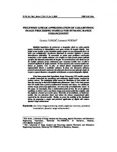
4. THE IMAGE ENHANCEMENT METHODS In this section an image enhancement method having as criteria the mean dynamic range maximization is presented. Firstly it is presented the method for monochrome images and then for the color ones. 4.1 The Enhancement Method for Monochrome Images Let be a monochrome image f : Ω → V , where V = [0,1] . Using the relations (3.12) the mean dynamic range Dm ( f ) = [vi , vs ] is computed. The transform that realizes the enhancement is a piecewise linear one. In fact the values that are less then vi are replaced by 0 , the values that are greater then v s are replaced by 1 and the values that belong to the mean dynamic range Dm ( f ) = [vi , vs ] are linear transformed in such a way to cover the entire interval V = [0,1] . One results the following function: 0 for v < vi v − vi (4.1) for v ∈ [ vi , vs ] T (v ) = vs − vi 1 for v > vs This method was used for the image “woman” shown in fig. 1. The enhanced image is shown in fig. 2 and the graphic of the transform T can be seen in fig. 3.
κ − γ2 ≥1 (3.9) Taking into account the relations (2.4) and (2.5), the Pearson inequality (3.9) has the following equivalent form:
Figure 1. The original image “woman”.
κ − 3α 2 ≥ α 2 + 1 (3.10) Using the following parameters: c = µ + σ ⋅ α (3.11) d = κ − 3α 2 and replacing them in (3.5) results: = µ + σ ⋅ α − σ ⋅ κ − 3α 2 v i (3.12) v s = µ + σ ⋅ α + σ ⋅ κ − 3α 2 Thus the relations (3.12) define a mean dynamic range larger then that defined by (3.8). Figure 2. The enhanced image.
578
Figure 3. The graphic of the transform T.
Figure 4. The original image “Lena”.
4.2 The Enhancement Method for Color Images A color image is described in the RGB coordinate system by three scalar functions: fG : Ω → V , fR : Ω → V , f B : Ω → V that define the red, green, blue components of the color. There are two possibilities to extend the method from the monochrome images to the color ones: a vector approach and a scalar one. 4.2.1 The Vector Approach In this approach, for each color component f R , fG , f B , using the relations (2.1), (2.2), (2.3), (2.5) and (2.6) one computes: µ( f R ), µ p ( f R ), σ( f R ), α( f R ), κ( f R )
( ) (µ( fG ), µ p ( fG ), σ( fG ), α( fG ), κ( fG )) (µ( f B ), µ p ( f B ), σ( f B ), α( f B ), κ( f B ))
Figure 5. The enhanced image.
Three mean dynamic ranges result: Dm ( f R ) = [vi ( f R ), vs ( f R )] Dm ( fG ) = [vi ( f G ), vs ( f G )] Dm ( f B ) = [vi ( f B ), vs ( f B )]
(4.2)
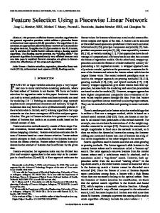
Thus, three distinct transforms T R , TG , T B are obtained. These transforms are defined for each color component f R , fG , f B by relation (4.1). The method was used for the color image ”Lena” shown in fig. 4. The enhanced image is presented in fig. 5 and the graphics of the transforms T R , TG , T B are shown in fig. 6. This method leads to a strong modification of color hue and can be used in the color correction procedure. 4.2.2 The Scalar Approach In this approach, only one set of parameters µ( f ) , µ p ( f ) is computed using the following formulae: 1 µ( f ) = (4.3) fX ∑ ∑ 3 ⋅ card (Ω) Ω X = R,G , B
Figure 6. The graphics of color component transforms.
µp( f ) =
1 ( f X − µ ( f ) )p ∑ ∑ 3 ⋅ card (Ω ) Ω X = R,G , B
(4.4)
for p = 2,3,4 . The calculus for the parameters σ( f ) , α ( f ) , κ( f ) is done using the relations (2.3), (2.5) and (2.6). Further, the mean dynamic range Dm ( f ) = [vi , v s ] is computed using the formulae (3.12) and then from (4.1) it results the transform T that will be applied to each color component f R , f G , f B .
579
The method was used for image “boat” shown in fig. 7. The enhanced image is presented in fig. 8 and the graphic of the transform T in fig. 9. Using a unique transform for all color components the method preserves quite well the color hue. 5. CONCLUSIONS In this paper there have been presented new enhancement methods for monochrome images and for color images. The methods are based on the mean dynamic range maximization using piecewise linear transforms. A new formula for the measure of the mean dynamic range was presented. The experimental results show that the new measure of the mean dynamic range is robust and has good performances.
Figure 7. The original image boat.
REFERENCES [1] K.R. Castleman. Digital Image Processing, Prentice Hall, Englewood Cliffs NJ, 1996. [2] R.C. Gonzales and P. Wintz. Digital Image Processing, 2nd Edition, Addison-Wesley, New York, 1987. [3] A.K. Jain. Fundamentals of Digital Image Processing, Prentice Hall Intl., Englewood Cliffs NJ, 1989. [4] M. Jourlin and J.C. Pinoli, “Image dynamic range enhancement and stabilization in the context of the logarithmic image processing model”, Signal processing, Vol. 41, no. 2, pp. 225-237, 1995. [5] V. Patrascu and V. Buzuloiu, “The mean dynamic range optimization in the framework of logarithmic models”. Advanced Topics in Optoelectronics, Microelectronics, and Nanotechnologies, Proc. SPIE, Vol. 5227, pp. 73-80, October 2003. [6] J.C. Pinoli and M. Jourlin. Modelisation & traitement des images logarithmiques. Publication Nr. 6, Departement de Mathematiques, Univ. de Saint-Etienne 1992. [7] W.K. Pratt. Digital Image Processing. 2nd Edition, Wiley / Interscience, New York, 1991. [8] V.K. Rohtagi and G.J. Szekely, “Sharp inequalities between skewness and kurtosis”, Statis. Probab. Lett. 8, pp. 297-299, 1989. [9] A. Rosenfeld and A.C. Kak, Digital Picture Processing. Academic Press, New York, 1982. [10] J.E. Wilkins, “A note on skewness and kurtosis”, Ann. Math. Statis. 15, pp. 333-335, 1944.
Figure 8. The enhanced image.
Figure 9. The graphic of color component transform.
580