0
Narendra Kumar Sharma and G R Sinha/ Elixir Elec. Engg. 95 (2016) 40933-40936 Available online at www.elixirpublishers.com (Elixir International Journal)
Electrical Engineering Elixir Elec. Engg. 95 (2016) 40933-40936
Image inpainting by Applying Reference Pixel Choosing Method Narendra Kumar Sharma1 and G R Sinha2 1
Department of Electronics And Telecommunication, Shri Shankaracharya Technical Campus, Bhilai, India. 2 Associate Director , Shri Shankaracharya Group Of Institution, Bhilai , India.
A R TI CLE IN FO
Arti cl e hi st or y: Received: 9 May 2016; Received in revised form: 8 June 2016; Accepted: 13 June 2016; Ke ywor d s Curvature Driven Diffusion CDD, Peak Signal To Noise Ratio PSNR, Partial Differential Equation, Image Inpainting.
AB STRACT Image inpainting is the science of filling in the missing or damaged area of an image from the enclosing area’s information. Its purpose is to recover images with limited data loss and tries to obtain inpainting outputs of damaged parts in such a way that the recovered images look usual. In our proposed method we will divide the damaged portion of image in the form of reference pixel according to their dissipating property. Then by applying image inpainting we have obtained an image whose visuable quality is identical to cover image.
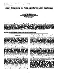
I.Introduction Image inpainting has been an operative area studied for last few years. Also known as image retouching or image restoration it is the science of reconstructing vanished or misplaced part of an image based on background data in an unusual fashion. The main purpose of this process is to fill the damaged or left out part of the image based on the information from neighboring areas in such a way that it cannot be found out by an attacker. Its application includes recovery of ancient films, object elimination in digital images, compression etc. II. Related Work The word inpainting was first popularized by M. Bertalmio et.al [1] in 2000 in connection with picture restoration as shown in figure 1(a) and figure 1(b). They suggested that inpainting can be implemented to recover damaged picture and also to remove unwanted objects. First of all diffusion based inpainting [2] taken into consideration in which damaged region was filled by diffusing image information on damaged area at the pixel point. This method has the disadvantage that it produced blur during inpainting process of big areas. Nitin Gopinath et.al [3] suggested a complex diffusion based algorithm which enhanced both clarity and speed by changing the undesired objects from information present in the nearby pixels. Some researchers have given texture synthesis based inpainting method [6]-[8] in which entire picture was searched for the matching neighboring pixels and used it for damaged points but when the picture is large the recovering process takes too much time. Then another algorithm known as partial differential equation [10] has introduced. It s a differential equation consist of one or more variables, correlating the values of function and its derivative, but fails when missing part is large. To overcome this drawback Lixin Yin et.al [11] has given an algorithm as exemplar based inpainting which taken into account the isophote shape as a Tele: 8982160365 E-mail address:
[email protected] © 2016 Elixir All rights reserved
© 2016 Elixir All rights reserved.
new factor to calculate patch priority and identical cost function. In 2011 Jianbing Yang [12] proposed Total Variant inpainting or TV model in which a precise iterative algorithm to concurrently recognized and recover missing part of an image is explained. This algorithm was unable to reconstruct fractionally damaged images. Some more researchers have presented their work by considering the utilization of mask to obtain inpainting. The mask that they have chosen for inpainting is determined by indicatively by and needs user interruption. They developed the mask such that centre component in the mast is zero. This implies that no knowledge about pixel is extracted using its own value (as it is the one to be regenerated and in image inpainting, it is assumed that the area to be inpainted does not possess any data). It takes the value of its surrounding pixels to calculate it’s value. But this method has a disadvantage that it only works well for small area in image and cannot inpaint large area in image [15]. This method hinted towards something identical to noise removal from image. De-noising is aimed towards modification in each different pixels whereas inpainting focused on modifying large area from the picture. De-noising is also different from image inpainting in a way that in image inpainting there is no knowledge about the image in the region to be inpainted in contrast to noise elimination where pixels may possess knowledge about both the real data and noise. Also, noise removal will in general not work for filling-in big damage parts in an image (e.g., in removal of an object).. In addition one more algorithm for reconstructing small area and noise in an image is proposed. Criminisi et al [16] suggested a approach in this area that connected structural recovery approach with the texture synthesis approach in one algorithm by calculating the advantages of both approaches.
0
Narendra Kumar Sharma and G R Sinha/ Elixir Elec. Engg. 95 (2016) 40933-40936
They adopted the fact that the output of inpainting process rely (in general) on the order of filling-in the hole. Also roughness with respect to the structure of the manually selected damaged region is also indicated. (3) E= [X (i-µ,j) + X(i+µ,j) + X(i,j-µ) + X(i,j+µ) – 4 Xmin(i,j,µ)]
Figure 1(a) Original Image
Figure 1(b) Damaged Image
(4) Where Xmax(i,j,µ) and Xmin(i,j,µ) are the maximum and minimum value in [X(i-µ,j), X(i+µ,j), X(i,j-µ), X(i,j+µ)] respectively which are nearly equal in our case, and T1 is a predecided threshold. Second, for each pixel x(i',j'), where 1≤i'≤M-µ and 1≤i'≤N-µ, the Q1(i,j) of the pixel belonging to the region i'≤i≤i'+µ, j'≤j≤j'+µ can be further mapped into Q(i,j) if its identical to Q1(i',j'), Q(i'+µ,j), Q(i',j'+µ) and Q(i'+µ,j'+µ) are all equal to 0. (5) where is also a function with binary input, i.e., 1 or 0, indicating whether or not region i'≤i≤i'+µ, j'≤j≤j'+µ belongs to the either smooth or complex region, The expression of the function is: (6) R= [P (i'-µ,j') + P(i'+µ,j') + P(i',j'-µ) + P(i',j'+µ) – 4 Pmin(i',j',µ)]
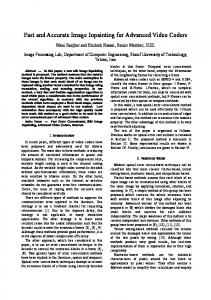
Figure 2. Block representation of proposed system. III. Proposed System In 2013 Chuan Qin et.al [13] given an algorithm for image inpainting known as curvature driven diffusion model or CDD model. In this, first they adopted adaptive reference pixel choosing method in which less reference pixels are chosen in the continuous region and large reference pixels are chosen in the complicated region. Then pixel prediction is done by third order partial differential equation to generate inpainted image which has similar structure as cover image. This method has somewhat minimized the limitation produced by TV model. This method of choosing reference pixels adaptively suggested by Chaun Qin et. al produced greater possibility of recovering back all the damaged pixels as it covers all the pixels from both smooth region and complex region. In our proposed method we have modified Chuan Qin et.al method by choosing equal number of reference pixels from both continuous and complicated region. The block diagram of proposed system is shown in figure 2. III. A Reference Pixel Choosing We Denote X(i, j) as the pixel value at the location (i, j) of the Damaged image X sized M × N. Assume that Q is a binary mask image with the similar size as the Damaged image X, which has the locations of reference pixels. (1)
Where i = 1, 2, . . . , M; j = 1, 2, . . . , N; and μ denotes the interval between the two nearby reference pixels. Based on the above step, we modified the reference pixels according to the characteristics of the damaged image. First, for each pixel P(i, j), where μ + 1 ≤ i ≤ M − μ and μ + 1 ≤j ≤ N − μ, Q0 (i, j) can be updated into Q1(i, j) by (2) related to mod (i+j,µ) = 2 where µ is a function with a binary output, i.e., 1 or 0, indicating whether the input pixel X(i,j) belong either smooth or complex. The expression of the function is
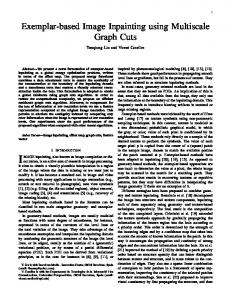
(7) Where Xmax(i',j',µ) and Xmin(i',j',µ) are the maximum and minimum value in [X(i'-µ,j'), X(i'+µ,j'), X(i',j'-µ), X(i',j'+µ)] respectively which is nearly equal in our case, and T2 is a predecided threshold. This can be shown by the output image obtained Based upon the equations and condition for reference pixels below are the output image obtained after this process
Figure 3 (a) shows the output image at T1 = 1and T2=10, figure 3 (b) shows the output image at T1 = 2 and T = 20, figure 3 (c) shows the output image at T1 = 3 and T2 = 30, figure 3 (d) shows the output image at T1 = 4 and T = 40. III. B Image Inpainting Using CDD Model The CDD (Curvature Driven Diffusion) model [2] applied to use the curvature information of the isophotes to handle the curved structures in a better way. Our modified CDD model is given by:
1
Narendra Kumar Sharma and G R Sinha/ Elixir Elec. Engg. 95 (2016) 40933-40936 Table 1. Comparison of PSNR values for Chuan Qin et. al method and proposed method after image inpainting process for figure 4 (d). T1 2 4 6 8
and (.) is the divergence operator. The transfer coefficient [14] of Curvature driven diffusion model is given by equation (10) To increase the inpainting time we have splitted coefficient from equation 2 so that the factor may improves the response time of inpainting process. Secondly, we have introduced mass function which protects the corners. So the new equation for CDD model is:
T2 20 40 60 80
PSNR Values at µ=4 Chuan Qin et. al method 37.06 dB 33.62 dB 31.29 dB 29.68 dB
Proposed Method 46.88 dB 45.77 dB 45.39 dB 45.20 dB
Table 2. PSNR values for proposed method after image inpainting process for different values of µ for figure 4 (a) Threshold µ=3 µ=4
T1 T2 PSNR in db PSNR in dB
1 10 44.63 47.34
2 20 43.57 46.17
3 30 43.19 45.70
4 40 43.03 45.50
Table 3. PSNR values for proposed method after image inpainting process for different values of µ for figure 4 (b) Threshold µ=3 µ=4
T1 T2 PSNR in db PSNR in dB
1 10 42.82 45
2 20 42.43 44.26
3 30 42.25 44
4 40 42.13 43.85
Table 4. PSNR values for proposed method after image inpainting process for different values of µ for figure 4 (c).
In general, we choose that: Where x(i,j) is the pixel value of any grad value (i,j). IV. Results and Comparisons Experiments and analysis were conducted on different test images of figure 4(a), 4(b), 4(c) and 4(d) with different size to determine the PSNR (peak signal to noise ratio).
Threshold µ=3 µ=4
T1 T2 PSNR in db PSNR in dB
1 10 43.40 45.91
2 20 42.94 45.37
3 30 42.74 45.02
4 40 42.60 44.78
Table 5. PSNR values for proposed method after image inpainting process for different values of µ for figure 4 (e). T1 1 2 3 4 Threshold T2 10 20 30 40 µ=3 PSNR in db 42.62 42.29 42.18 42.11 µ=4 PSNR in dB 44.70 44.12 43.97 43.86
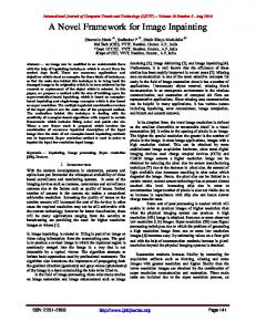
Figure 5 PSNR values for various test images for different threshold values. V. Conclusion In order to enhance the recovery process of damaged images, an image inpaiting algorithm based on reference pixel choosing method of damaged image has proposed in which nearly equal number of reference pixel were chosen from damaged imaged. According to the pixel chosen a modified CDD based inpainting method has applied to effectively generate the output image which is quite similar or shape wise identical to cover image which was used before damaged, The strategy of choosing reference pixel produced greater possibility for recover of damaged image without much distortion. Experiments were conducted on some gray scale image. Figure 5 shows that the proposed scheme results in better PSNR values for different test images which in turns produced greater possibility of recovering back the undamaged image.
2
Narendra Kumar Sharma and G R Sinha/ Elixir Elec. Engg. 95 (2016) 40933-40936
References [1] M.Bertalmio,G.Sapiro, V.Caselles and C.Ballester, "Image inpainting", in Siggraph 2000, Computer Graphics Proceedings, PP.417-424, ACM Press / ACM SIGGRAPH / Addison Wesley Longman, 2000. [2] Bansi B. Thanki, “Overview of an image inpainting techniques”, International Journal For Technological Research In Engineering, vol.2 , issue 5, jan. 2015, page 388-391. [3] Nithin Gopinath, Arjun k and J Adithya Shankar Jyothisha J Nair, “Complex Diffusion Based Image Inpainting”,1st International Conference On Next Generation Computing Technologies, 4-5 sep. 2015,page 976-980. [4] Weiliang Fan, Jing M. Chen, Weimin Ju, “A Pixel Missing Patch Inpainting Method for Remote Sensing Image”, International Institute for Earth System Sciences, 2011. [5] Eman T. Hassan_, Hazem M. Abbasy, Hoda K. Mohamed, “Image Inpainting Based on Image Segmentation and Segment Classification”, IEEE International Conference on Control System, Computing and Engineering, 29 Nov. - 1 Dec. 2013, page 28-33. [6] Chuang Zhu, Huizhu Jia, Meng Li, Xiaofeng Huang, Xiaodong xie, “Highly Efficient Local Non-Texture Image Inpainting Based on Partial Differential Equation”, IEEE 17th International Conference on Computational Science and Engineering, 2014, page 803-807. [7] Geeta K.Sarpate, Shanti K.Guru, “Image Inpainting on Satellite Image Using Texture Synthesis & Region Filling Algorithm”, International Conference on Advances in Communication and Computing Technologies 2014. [8] Abdul R. Zubair,”A Non-Iterative Automated Mechanism for Image Inpainting”, 3rd IEEE International Conference on Adaptive Science and Technology (ICAST 2011), page 193199. [9] Aarti S. Deshmukh, Dr. P. Mukherji,’’Image Inpainting Using Multi resolution Wavelet Transfrom Analysis’’, International Conference on Communication, Information & Computing Technology (ICCICT), Oct. 19-20,2012, Mumbai, India, page 1-6. [10] Zhongyu Xu, Xiaoli Lian, Lili Feng,’’ Image Inpainting Algorithm Based on Partial Differential Equation’’, ISECS International Colloquium on Computing, Communication, Control, and Management,2008, page 120-124. [11] Lixin Yin, Chen Chang,’’ An Effective Exemplar-based Image Inpainting Method’’,IEEE conference on signal and image processing, 2012, page 739-743. [12] Jianbin Yang, ‘’ A TV-based Approach On Blind Image Inpainting’’, 4th International Conference On Image And Signal Processing, 2011, page 779-781. [13] Ying-Hsuan Huang, and Li-Ting Liao,’’ An InpaintingAssisted Reversible Steganographic Scheme Using a Histogram Shifting Mechanism’’, IEEE Transaction On Circuits And Systems For Video Technology, Vol. 23, No. 7, JULY 2013, page 1109-1118. [14] Baoyong Yin, Shangping Qiao, Jiansheng Liu, Mingming Li,” The Research and Application of Digital Image Inpainting Based on Improved CDD model”, International Journal of Computer and Information Technology, Volume 02– Issue 04, July 2013, page 772-779. [15] Mr. Mahesh Mahajan, Mr. Praveen Bhanodia,“Image Inpainting Techniques for Removal of Object”, ICICES2014 S.A.Engineering College, Chennai, Tamil Nadu, India. [16] A, Criminisi, P. Perez, and K. Toyama, "Region filling and object removal by exemplar-based image inpainting," IEEE Transactions on Image Processing, 2004, 13(9) 1200-1212.
[17] Yongsheng Xu, Shuwen Wang,” “Image Inpainting Based on Wavelet Transformation”,page 541-544. [18] Zhen Xie, Fan Zhan*, Conggui Zhang,”An Adaptive Matching Algorithim for Image Inpainting”, page 1293-1296.