The method assumes that the natural images have ... Fractal-based methods assume that each block of an ... For accelerating the segmentation and inpainting.
Fast and Accurate Image Inpainting for Advanced Video Coders Mani Ranjbar and Shohreh Kasaei, Senior Member, IEEE Image Processing Lab, Department of Computer Engineering, Sharif University of Technology, Tehran, Iran Abstract — In this paper, a new still image inpainting method is proposed. The method assumes that the natural images have the fractal property. The main assumption in these images is that each small block of an image can be replaced using another block contained in that image using translation, scaling, and zooming properties. In our method, a very fast and flexible segmentation algorithm is used which plays a considerable role in the performance of the overall algorithm. In contrary with the previous methods which have employed a fixed block shape, content dependent block shapes are used in our method. Low calculation time accompany with the high quality result have made this method as a good choice to be used in the error concealment part of advanced video coders. Index Terms — Fast Error Concealment, Still Image Inpainting, Advanced Video Coders, Internet.
I. INTRODUCTION In recent years, different types of video coders have been proposed and extensively used for diverse applications. The main idea in these methods is reducing the amount of correlated information in spatial and temporal domain. For increasing the compression ratio, variable length coding is used in the channel coding module. As the variable length codes cannot be decoded without synchronization information, these codes are very sensitive to bitwise errors. On the other hand, available networks such as the Internet or wireless networks do not guarantee error-free communications. Hence, the issue of coping with the occurred error should be considered carefully. There are different types of methods to suppress the communication error reported in the literature. One strategy is to use a feedback channel for requesting retransmission [1]. Due to the imposed delay, this strategy is not applicable in many interactive applications. The other strategy is to insert some resilient codes into the coded information such that the decoder could recover the erroneous frames [2], [3], [4]. Although these methods provide good performance, it is at the expense of lower compression efficiency. The other approach, which has considered in this paper, is to use an error concealment technique in the decoder to conceal the erroneous blocks in a frame [5], [6]. Two general types of error concealment methods have been studied in the literature, spatial and temporal. Spatial error concealment techniques attempt to recover the erroneous blocks of a frame using correctly decoded
blocks in that frame. Temporal error concealment techniques, on the other hand, employ the information of the neighboring frames for correcting a frame. Advanced video coders such as MPEG-4 and H.264, classify the video frames in three groups: I-Frame, PFrame and B-Frame. I-Frames, which no temporal information exists for them, can only be concealed with spatial error concealment methods, but P-Frames can be concealed by either spatial or temporal methods. In this work, a new spatial error concealment method is proposed which can be used effectively for I-Frame error concealment. In addition to reconstruction of edges and flat regions, this method can reconstruct the textures properly. The other advantage of this method is its very easy threshold adjusting. The rest of this paper is organized as follows. Previous works on spatial error concealment is reviewed in Section II. The proposed method is discussed in Section III. Some experimental results are shown in Section IV. Finally, conclusions are given in Section V. II. PREVIOUS WORK Modern spatial error concealment techniques can be classified into four main classes: fractal-based, tensor voting-based, stochastic-based, and interpolation-based. Fractal-based methods assume that each block of an input image can be reconstructed using other blocks of the same image by applying translation, rotation, and zooming. In [7], a simple method of this group has been proposed which conceals the whole erroneous block with another block of that image after adjusting its intensity. Advanced version of this method has been proposed in [8] which divides the damaged block into small blocks and searches for each subblock independently. The major weakness of this method is its content independent lock division. Other methods of this group have been proposed in [9], [10], [11], [12]. Tensor voting-based methods calculate the tensors around the damaged block and approximate the tensor of the lost pixels by voting [13]. Although these methods produce very good results, but real-time implementation of them is impossible due to their high complexity. Stochastic-based methods use the statistical characteristics of pixels around the lost block to approximate its pixel values. They often assume a Markov model to simplify their calculation and employ
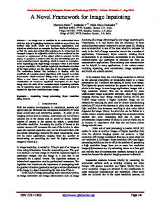
the Bayesian formula to describe the problem. Using the MAP algorithm in some iterations the problem is solved [14]-[15]. These methods usually have two major weaknesses: they yield blur results because of the simplifying assumptions and high complexity due to the required iterations. Interpolation-based methods attempt to interpolate the pixel values in the lost block using border pixels of that block. In [16], a very fast method has been proposed that conceals the erroneous block with the aim of directional interpolation. In [17], the advanced version of this method has been proposed which can cope with more difficult situations. Weakness in texture reconstruction is their major limitation. The aim of our proposed method is to overcome the shortcoming of the fractal-based and interpolation-based methods (which is content independent block shape and poor texture reconstruction) and to design a fast and accurate error concealment method. III. PROPOSED METHOD In this section, the proposed method is described. It consists of three main blocks: image segmentation, segmentation matching, and inpainting. The block diagram of our algorithm is shown in Fig. 1. In the following, each block is discussed in detail.
Figure 1. Block diagram of proposed concealment method.
A. Cropping Algorithm For accelerating the segmentation and inpainting process, input image is cropped around the erroneous block with the following formulas.
C x = Max(0, Errx − Gapx )
(1)
C y = Max(0, Erry − Gap y )
(2)
C w = Min(I w − Errx , Errw + Gapx )
(3)
C h = Min(I h − Erry , Errh + Gap y )
(4)
where C denotes the cropped image, Err denotes the erroneous block, and Gap denotes the gap size between erroneous block and cropped block. Our experiments showed that an efficient gap size is 1.5 times of erroneous block width (height). Less gap size, yields less inpainting quality, and bigger gap size imposes additional complexity. B. Segmentation Algorithm Our research showed that when one is asked to inpaint the erroneous block, s/he first segments the region around the damaged block. After that, s/he attempts to connect the broken segments and then inpaints each segment individually. Thus, we tried to imitate this method. Due to the high complexity of the segmentation algorithms, we sought for an efficient segmentation algorithm and adopted the method reported in [18]. In the following, a brief overview of that method is first given. • Input: Graph G=(V, E) with n vertices (V) and m edges (E). • Output: Segmentation of V into components of S=(C1, …, Cr) 0- Sort E into s=(o1, …, om), by non-decreasing edge weights. 1- Start with Segmentation S0, where each vertex vi is in its own component. 2- Repeat step 3 for q=1, …, m. 3- Construct Sq given Sq-1 as follows. Let vi and vj denotes the vertices connected by the qth edge in order; i.e., oq = (vi, vj). If vi and vj are in disjoint components of Sq-1, and w(oq) is small compared to the internal difference of both those components, then merge the two components otherwise do nothing. More formally, let Ciq-1 be the component of Sq-1 containing vi and Cjq-1 the component containing vj. If Ciq-1 ≠ Cjq-1 and w(oq) ≤ Mint( Ciq-1, Cjq-1), then Sq is obtained from Sq-1 by merging Ciq-1 and Cjq-1. Otherwise Sq = Sq-1. 4- Return S = Sm.
For more information about this segmentation method, please refer to [18]. C. Segment Matching Algorithm After applying the segmentation procedure, image segments around the lost block are obtained. Segment Matching algorithm is then engaged to approximate the border of segments contained inside the erroneous block. By using these borders we can inpaint each segment region individually. Fig. 2. shows the steps of segment matching algorithm.
a
c
D. Inpainting Algorithm After extracting region masks in the segment matching stage, each mask is inpainted individually in this stage. For convenience, mask 'a' of Fig. 2-d is magnified in Fig. 3.
Figure 3. Magnified region 'a' of Fig. 2-d with erroneous part Ψ and reliable border η.
B
D
Figure 2. Steps of matching segment algorithm: a) segmented image, b) entry point extracted image, c) segment matched image, d) mask extracted image.
As shown in Fig. 2, segment matching consists of three steps. First, the intersections of segment borders with erroneous block sides are calculated (Fig. 2-b). Then, a straight line is assumed to connect the entry points of those segments that have borders in different sides of the lost block and also the difference of their entrance angles are about 180 degrees (Fig. 2-c). Finally, different regions that have been created by estimated these lines are considered as the inputs of the inpainting process. The procedure can be formulated by
i ≠ j i, j ∈ (1,.., n ) ⎧ ⎪ S(pi ) I S( p j ) ≠ ∅ ⎪ ⎪ 1 L( pi , p j ) = ⎨ 90 < θ( pi ) − θ( p j ) < 270 ⎪ ⎪ ⎪⎩ 0 Otherwise
where n is the number of junction points, S(p) denote the indices of neighboring segments of point p, and Ө(p) is the entrance angle of segment border at point p. Inner border of masks are the lines between points i and j for which L(pi ,pj ) is equal to 1. After finding the borders of each mask, the inpainting algorithm is engaged to conceal them individually.
⎫ ⎪ ⎪ ⎪ (5) ⎬ ⎪ ⎪ ⎪⎭
For inpainting the Ψ part of mask 'a', four steps should be applied. I) A border mask denoted by η in Fig. 3 is created around the input mask. The width of this border mask can be adjusted by the user. This border mask consists of reliable information of original image. II) The search region is defined. In our proposed method the search region is defined easily. Since we know the segments that surround the input mask, those segments are used as the searching region. For instance, Segment 1 is the search region for mask 'a', Segment 3 is the search region for mask 'c', and Segment 2, 4, 5 and 6 are used for inpainting mask 'b'. III) The best match which minimizes the absolute error between η and η' is found (η' is the border of remote mask). IV) After adjusting the mean of Ψ', the Ψ is replaced by the Ψ' region of the remote mask. We can formulate the inpainting method by
⎧⎪Err(m) = ∑ I(η) − I(ηm) + μ(I(ηm)) − μ(I(η)) ⎨ ⎪⎩ for m = {m'| ηm' ∩ ω ≠ ∅} (6)
R = arg min{Err ( m )}
(7)
m
I(Ψ ) = I(ΨR ) + μ(I(η)) − μ(I(η R ))
(8)
where I returns the image value, µ denotes the mean value, ω is the search region, and ηm is the border of remote mask m.
IV. EXPERIMENTAL RESULT The proposed algorithm is tested on some standard still images and different QCIF formatted video sequences using OpenCV package. Two types of result are presented in this section. In Fig. 4, the output of our method in different situations is shown. In Figs. 5 and 6, our proposed method is compared to some previously reported methods. Our results are achieved unsing the following parameters: σ(segmentation)=0.5, k(segmentation)=100, min (segmentation)=100, Gapx=1.5¯Errx, Gapy=1.5¯Erry. In Fig. 4, four different situations that may occur around the erroneous block are tested. In Fig. 4-a first frame of "Foreman" sequence is employed that has flat regions with strong edges. Fig. 4-b shows the ability of the proposed method in edge reconstruction. In Fig. 4-c another scene containing complex textures is used. Fig. 4-d shows that the proposed method can cope with the combination of complex structures, flat regions, and strong edges. In Figs. 5 and 6 the performance of our proposed method is compared to that of previously reported methods. Two methods from two different categories are selected for comparison purposes; fractal-based method [7] and interpolation-based method [16]. In Fig. 5, a region with texture, flat segment, and strong edges is considered for evaluating three methods. As the results show, our proposed method has been able to conceal the erroneous block perfectly while two other methods have failed. The method in [7] failed because it attempts to conceal the block at once, and the method in [16] failed because it cannot detect the accurate angles in complex textures. In Fig. 6, the ability of our proposed method for detecting common structures is shown. Whereas this ability has been inherited from fractal-based methods, the result of our method is the same as the method in [7] in this situation. Computational complexity of the proposed method is presented in Table 1. As this table shows, the proposed method can be executed in real-time. Note that, in applicable applications the rate of I-Frames, which do not have temporal information, is at most the half of the video rate.
detect the common structures in an image. Finally, we showed that our method can be executed in real-time for I-Frame concealment purposes.
a
b
c
d
Figure 4. Results of proposed method in four different situations: a) erroneous frame without complex texture containing strong edges, b) concealed frame without edge discontinuity, c) erroneous frame with complex texture, d) concealed frame with perfect texture reconstruction.
a
b
c
d
V. CONCLUSION In this paper, we have proposed a fast and accurate image inpainting method. The proposed method has the ability of fractal-based and interpolation-based methods together. We illustrated the superiority of our proposed method among two previously reported methods via some experimental results. We demonstrated the power of our method to cope with complex scenes and also to
Figure 5. Comparison among the proposed method and two other methods in a complex scene: a) erroneous image, b) result of method [7], c) result of method [16], d) result of our proposed method.
a
b
c
d
Figure 6. Comparison among the proposed method and two other methods in a special case: a) erroneous image, b) result of method [7], c) result of method [16], d) result of our proposed method. Table1: Computational complexity of the proposed method.
CPU
RAM
Lost Size
Search Size
Time (ms)
PIII 700MHz PIV 3GHz
640M B
32*32
128*128
210
1GB
32*32
128*128
85
ACKNOWLEDGEMENT This work was in part supported by a grant from ITRC. REFERENCES [1] B. Girod, and N. Farber, “Feedback-based error control for mobile video transmission,” Proc. IEEE, vol. 87, no. 10, pp. 1707-1723, October 1999. [2] J. Hagenauer, and T. Stockhammer, “Channel coding aspects for wireless multimedia,” Proc. IEEE, vol. 87, no. 10, pp. 1764-1777, October 1999. [3] S. B. Wicker, “Error control systems for digital communication and storage,” Englewood Cliffs, NJ: Prentice Hall, 1995. [4] V. K. Goyal, “Multiple description coding: compression meets the network,” IEEE Signal Process. Mag., vol. 18, no. 5, pp. 74-93, September 2001. [5] B. W. Wah, X. Su, and D. Lin, “A survey of errorconcealment schemes for real-time audio and video transmission over the internet,” in Proc. Int. Symp. Multimedia Software Engineering, pp. 17-24, December 2000.
[6] P. Cuenca, L. Orozco-Barbosa, A. Garrido, F. Quiles, and T. Olivares, “A survey of error concealment schemes for MPEG-2 video communications over ATM network,” in Proc. IEEE Can. Conf. Elect. and Comp. Eng., vol. 1, pp. 25-28, May 1997. [7] D. Zhang, and Zh. Wang, “Image Information Restoration Based on Long-Range Correlation,” IEEE Trans. on Circuits and System, vol. 12, no. 5, May 2002. [8] Antonio Criminisi, Patrick Pérez and Kentaro Toyama, “Region Filling and Object Removal by Exemplar-Based Image Inpainting,” IEEE Trans. On Image Processing vol. 13, no. 9, September 2004 [9] M. Ashikhmin, “Synthesizing natural textures,” in Proc. ACMSymp. Interactive 3D Graphics, pp. 217-226, Mar. 2001. [10] A. Efros, and W. T. Freeman, “Image quilting for texture synthesis and transfer,” in Proc. ACM Conf. Computer Graphics (SIGGRAPH), pp. 341-346, August 2001. [11] A. Efros, and T. Leung, “Texture synthesis by nonparametric sampling,” in Proc. Int. Conf. Computer Vision, Kerkyra, Greece, pp. 1033-1038, Sept. 1999. [12] A. Hertzmann, C. Jacobs, N. Oliver, B. Curless, and D. Salesin, “Image analogies,” in Proc. ACMConf. Computer Graphics (SIGGRAPH), Aug. 2001. [13] Jiaya Jia, and Chi-Keung Tang, “Inference of Segmented Color and Texture Description by Tensor Voting,” IEEE Trans. on Pattern Analysis and Machine Intelligence, vol. 26, no. 6, June 2004. [14] P. Salama, N. B. Shroff, and E. J. Delp, "A Bayesian Approach to Error Concealment in Encoded Video Streams," Proceedings of the International Conference on Image Processing, September 1996. [15] Zhiliang XU, Shengli Xie, “An Efficient Spatial Error Concealment for Video Transmission,” Proceedings on Communications, Circuits and Systems, IEEE, 2005. [16] Wei-Ying Kung, Chang-Su Kim, and C.-C. Jay Kuo, ”Spatial and Temporal Error Concealment Techniques for Video Transmission over Noisy Channels,” IEEE Trans. on Circuits and Systems for Video Technology, vol. 16, no. 7, July 2006. [17] Wenjun Zeng, and Bede liu, ”Geometric-structure-based Error Concealment with Novel Applications in Blockbased Low Bit Rate Coding,” IEEE Trans. on Circuits and systems for Video Technology, June 1999. [18] P. F. Felzenszwalb, and D. P. Huttenlocher, “Efficient Graph-Based Image Segmentation,” International Journal of Computer Vision, vol. 59, pp. 167-181, September 2004.