wireless communication technology that uses low-power light-emitting diodes (LEDs) to not only provide light, but also broadcast data [1â3]. LEDs are extremely ...
YAMAZATO_LAYOUT_Layout 7/2/14 3:25 PM Page 88
VISIBLE LIGHT COMMUNICATIONS
Image-Sensor-Based Visible Light Communication for Automotive Applications Takaya Yamazato, Isamu Takai, Hiraku Okada, Toshiaki Fujii, Tomohiro Yendo, Shintaro Arai, Michinori Andoh, Tomohisa Harada, Keita Yasutomi, Keiichiro Kagawa, and Shoji Kawahito
ABSTRACT
Takaya Yamazato, Hiraku Okada, and Toshiaki Fujii are with Nagoya University. Isamu Takai is with Toyota Central R&D Labs., Inc. and Shizuoka University. Tomohiro Yendo is with Nagaoka University of Technology. Shintaro Arai is with Kagawa National College of Technology. Michinori and Tomohisa Harada are with Toyota Central R&D Labs., Inc. Keita Yasutomi, Keiichiro Kagawa, and Shoji Kawahito are with Shizuoka University.
88
The present article introduces VLC for automotive applications using an image sensor. In particular, V2I-VLC and V2V-VLC are presented. While previous studies have documented the effectiveness of V2I and V2V communication using radio technology in terms of improving automotive safety, in the present article, we identify characteristics unique to image-sensor-based VLC as compared to radio wave technology. The two primary advantages of a VLC system are its line-of-sight feature and an image sensor that not only provides VLC functions, but also the potential vehicle safety applications made possible by image and video processing. Herein, we present two ongoing image-sensor-based V2I-VLC and V2VVLC projects. In the first, a transmitter using an LED array (which is assumed to be an LED traffic light) and a receiver using a high-framerate CMOS image sensor camera is introduced as a potential V2I-VLC system. For this system, real-time transmission of the audio signal has been confirmed through a field trial. In the second project, we introduce a newly developed CMOS image sensor capable of receiving highspeed optical signals and demonstrate its effectiveness through a V2V communication field trial. In experiments, due to the high-speed signal reception capability of the camera receiver using the developed image sensor, a data transmission rate of 10 Mb/s has been achieved, and image (320 × 240, color) reception has been confirmed together with simultaneous reception of various internal vehicle data, such as vehicle ID and speed.
INTRODUCTION Visible light communication (VLC) is an optical wireless communication technology that uses low-power light-emitting diodes (LEDs) to not only provide light, but also broadcast data [1–3]. LEDs are extremely energy-efficient and are expected to become widespread in general lighting applications. Because LEDs are solid-state lighting devices, they can be modulated at high
0163-6804/14/$25.00 © 2014 IEEE
speed compared to other lighting sources. VLC uses LEDs to send data by flashing light at speeds that are undetectable to the human eye. The widespread use of LEDs in traffic applications and the growing interest in intelligent transport systems (ITS) presents a number of opportunities for VLC applications. Data transmission using LED traffic lights and LED brake lights is a typical application [3, 4]. While previous studies have documented the effectiveness of vehicle-to-infrastructure (V2I) and vehicle-tovehicle (V2V) communication using radio technology in terms of improving automotive safety [5, 6], in the present article, we introduce the concepts of V2I-VLC and V2V-VLC. In V2I and V2V systems, VLC offers several advantages. Since VLC links are visible, installation of roadside equipment is much easier. Additionally, previously installed facilities, such as LED traffic lights or LED sign boards, can be used. Furthermore, since the transmitters, or LED light sources, are designed for lighting purposes (and thus generally have high radiation power), the signal-to-noise ratio (SNR) is high for VLC, while eye safety is maintained for dualuse lighting, defined here as VLC incorporated with LED illumination. The visible light spectrum is not regulated globally, and its bandwidth extends from 400 up to 790 THz. The large (390 THz) available bandwidth provides attractive opportunities for ITS applications. Furthermore, V2I and V2V communications using radio technology can be used simultaneously with VLC, with each using a different spectrum. VLC provides an additional feature if the receiver incorporates an image sensor or a camera. Specifically, by using image or video processing to detect and recognize moving vehicles, safety applications can be integrated. For example, as methods of enhancing driving safety, adaptive cruise control, collision warning, pedestrian detection, and providing range estimations for nearby vehicles are potential candidates for incorporation into VLC systems. In this article, we introduce VLC application to ITS while focusing on an image sensor as a reception device. After starting with an overview of an image sensor as a VLC reception device,
IEEE Communications Magazine • July 2014
YAMAZATO_LAYOUT_Layout 7/2/14 3:25 PM Page 89
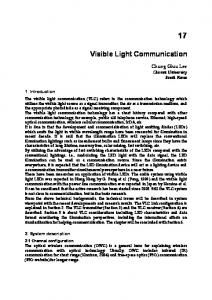
A variety of experimental and prototype VLC systems have been demonstrated for transportation applications. These include a 4.8 kbps visible light ID used as a mobile application infrastructure, and a lighthousebased maritime naviLED traffic light LED traffic signal to vehicle (V2I-VLC)
gation VLC system that transmits signals from buoys over ranges of up to 2 km.
Camera
Camera
LED brake lights to vehicle (V2V-VLC)
Figure 1. Vehicle-to-infrastructure visible light communication (V2I-VLC) using an LED traffic light and vehicle-to-vehicle visible light communications (V2V-VLC) using LED headlights or LED brake lights. we then introduce a safety support prototype using V2I-VLC and describe the results of a field trial. We then introduce a special complementary metal oxide semiconductor (CMOS) image sensor designed for receiving high-speed optical signals, and describe the result of a field trial of our first-step V2V communication system using the developed CMOS image sensor.
V2I VLC AND V2V VLC To date, a variety of experimental and prototype VLC systems have been demonstrated for transportation applications. These include a 4.8 kb/s visible light ID used as a mobile application infrastructure and a lighthouse-based maritime navigation VLC system that transmits signals from buoys over ranges of up to 2 km, both demonstrated by the Visible Light Communications Consortium (VLCC). VLCC also demonstrated the effectiveness of visible light identification (ID) systems in aircraft takeoff and landing operations. In [7], Haruyama et al. demonstrated successful 1 Gb/s free-space optical (FSO) communication transmissions to highspeed trains from trackside stations. Of course, needless to say, a significant amount of interest is currently focused on VLC automotive applications. Figure 1 shows an overview of a V2I-VLC and V2V-VLC traffic safety network environ-
IEEE Communications Magazine • July 2014
ment that includes an LED traffic light, LED headlights, and LED brake lights. V2I-VLC involves the wireless exchange of critical safety and operational data between moving vehicles and roadway infrastructure, and is identical in concept to V2I using radio wave technology, except that it uses light transmission instead of radio wave technology. By creating a networked environment between vehicles and infrastructure, V2I-VLC facilitates safe driving by adaptive traffic signal control, intersection movement assistance, speed management, and so on. This is also true for V2V-VLC, which involves wireless exchanges of data between moving vehicles traveling in the same area. Potential applications of V2V systems include emergency brake light warnings, forward collision warnings, and control loss warnings. It is generally accepted that VLC links depend on the existence of an uninterrupted line of sight (LOS) path between the transmitter and the receiver. In contrast, radio links are typically susceptible to large fluctuations in received signal amplitude and phase. Unlike radio waves, VLC does not suffer from multipath fading, which significantly simplifies the design of VLC links. Because VLC signals travel in a straight line between a transmitter and a receiver, they can easily be blocked by vehicles, walls, or other opaque barriers. This signal confinement makes it easy to limit transmissions to vehicles nearby.
89
YAMAZATO_LAYOUT_Layout 7/2/14 3:25 PM Page 90
CMOS image sensors
(X2, Y2)
Data B
have gained popularity in recent years
Photo diode
because of advances
Noise sources (the sun, streetlights, etc.)
in multi-functionalization, low manufacturing costs, and low power consumption. The key
LED of infrastructure data A
Image sensor
element of a CMOS image sensor is the photo diode, which
(X1, Y1)
Data A
is one component of
(X3, Y3)
Noise
LED of vehicle data B
a pixel. Figure 2. Advantage of image-sensor-based VLC.
Thus, VLC networks can potentially achieve remarkably high aggregate capacity and simplified design because transmissions outside communication range need not be coordinated. In other words, it is not necessary to consider sources outside visual range. It should be noted, however, that VLC has several potential drawbacks. First, since visible light cannot penetrate walls or buildings, VLC coverage is restricted to small areas, and some applications, such as blind spot warning, will require installation of access points that must be interconnected via a wired backbone. Furthermore, in addition to outright physical blocks, thick fog or smoke can blur visible light links and decrease system performance. In short-range VLC applications, the SNR of a direct detection receiver is proportional to the square of the received optical power. Therefore, VLC links can tolerate only a comparatively limited amount of signal path loss.
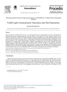
USE OF AN IMAGE SENSOR FOR VLC AN IMAGE SENSOR AS A RECEPTION DEVICE FOR VLC CMOS image sensors have gained popularity in recent years because of advances in multi-functionalization, low manufacturing costs, and low power consumption. The key element of a CMOS image sensor is the photo diode (PD), which is one component of a pixel. PDs are typically organized in an orthogonal grid. In operation, light passing through a lens strikes a PD, where it is converted into a voltage signal and then passed through an analog-to-digital converter. The converter output is often referred to as a luminance. Since a CMOS image sensor is composed of a PD array, PD outputs, specifically light intensity or luminance values, are arranged in a square matrix to form a digital electronic representation of the scene. A CMOS image sensor can also be used as a VLC reception device. Figure 2 shows examples for a V2I-VLC system in which LEDs in a traffic light transmit data, and a V2V-VLC system in
90
which the LED brake lights in a lead vehicle transmit data to a following vehicle [4]. A particular advantage of CMOS image sensor usage is, due to the massive number of pixels available, its ability to spatially separate sources. Here, the sources include both noise sources, such as the Sun, streetlights, and other ambient lights, and LED transmission sources. If a single-element PD is used as a VLC reception device, the VLC system cannot be used in direct sunlight. This is because direct sunlight is typically strong, and can often be received at an average power that is much higher than that of the desired signal. Furthermore, it is very difficult to reduce the enormous amount of noise signals summing all background lights in the field of view (FOV) to the optical signal level, even if an optical band-pass filter (OBPF) is used. Therefore, when a single-element PD is used outdoors, directed linkage with small optical beam divergence is necessary. Otherwise, the PD cannot be used in direct sunlight. In some cases, a receiver equipped with a telephoto lens that achieves an extremely narrow FOV can be used [7, 8], but this type of receiver is unsuitable for mobile usage because it limits the angle of incidence and requires complex mechanical tracking. In contrast, because of its ability to separate sources spatially, a VLC receiver utilizes only the pixels that it recognizes as LED transmission sources and discards all other pixels, including those detecting noise sources. The ability to spatially separate sources also provides an additional feature to VLC, specifically, the ability to receive and process multiple transmitting sources. As shown in Fig. 2, data transmitted from an LED traffic light sign and data transmitted from LED brake lights of a vehicle ahead can be captured simultaneously. Furthermore, if a source is composed of multiple LEDs, as in the case of LED traffic lights or brake lights, parallel data transmission can be accomplished by modulating each LED independently. The output of the CMOS image sensor form-
IEEE Communications Magazine • July 2014
YAMAZATO_LAYOUT_Layout 7/2/14 3:25 PM Page 91
ing a digital electronic representation of the scene further provides unique opportunities that cannot be realized by a single-element PD or radio wave technology, specifically, the ability to utilize a multitude of image or video processing technologies, such as position estimation, object detection, and moving target detection, simultaneously via the data reception capability of a VLC. For example, let us consider a situation where a vehicle is equipped with a CMOS image sensor. To begin, a VLC signal transmitted from a vehicle nearby is captured along with its spatial position (X, Y), or the actual row and column position of a pixel. This means that the VLC signal can be represented not only by a time domain signal, but also by the direction of the incoming vector from the transmitter to the receiver [9]. Consequently, requisite position data, which can be obtained by GPS or some other position estimation system that does not need to be transmitted, are already available.
HIGH-SPEED OPTICAL SIGNAL RECEPTION Most CMOS image sensors are designed in consideration of the characteristics of the human eye. A typical example is the frame rate of commercially available CMOS image sensors, which are generally limited to 30 fps or several multiples of 30 fps. Despite this, the demand for realtime high-frame-rate (HFR) image processing technology is increasing in various applications, including robotics, factory automation, multimedia, and biomedical fields [10]. Needless to say, VLC for automotive applications requires HFR image-processing technology. Assuming a CMOS image sensor with a frame rate of 30 fps, the transmission rate, or equivalently the “blink” rate of an LED, must be less than or equal to 15 Hz to satisfy the Nyquist frequency. However, this may be too slow, and humans may be able to recognize (and be distracted by) such blinking. Additionally, if a vehicle is moving at a speed of 36 km/h, or 10 m/s, the vehicle will receive a 15 b/s data signal every 10 m. This rate exceeds the permissible level. Furthermore, this rate makes the development of image processing technology for detecting and recognizing moving vehicles, or a transmitter located on the road, far more difficult because the vehicle moves 0.67 m during a single frame. In contrast, if the frame rate is boosted to 1000 fps, the vehicle moves just 0.01 m per frame. This not only simplifies the image processing required for detecting and recognizing moving vehicles, it also increases the data rate to 500 b/s. Accordingly, HFR CMOS image sensors are mandatory for VLC systems intended for use in automotive applications. An alternate approach is to integrate a receiver function into a conventional image sensor. Because of spectacular advances in CMOS process technology, the development of such a multi-purpose CMOS image sensor is straightforward. Furthermore, such a sensor not only maximizes data reception performance, but it also provides electric images suitable for image and video processing. Next, we describe a newly developed CMOS image sensor in which communication pixels that
IEEE Communications Magazine • July 2014
have been specialized for receiving high-speed optical signals are integrated with ordinary image pixels into a pixel array.
VEHICLE-TO-INFRASTRUCTURE VISIBLE LIGHT COMMUNICATIONS In this subsection, we introduce a V2I-VLC system using an LED array transmitter, which is assumed to be an LED traffic light, and an invehicle receiver equipped with an HFR CMOS image sensor camera, or high-speed camera [11].
Most CMOS image sensors are designed in consideration of the characteristics of the human eye. A typical example is the frame rate of commercially available CMOS image
SYSTEM OVERVIEW
sensors, which are
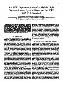
Figure 3 shows a block diagram of the system. The transmitter consists of an encoder, an inverted LED pattern insertion unit, a pulse-width modulator (PWM), and 1024 LEDs arranged in a 32 × 32 square matrix. The LEDs are the same as those used in LED traffic lights in Japan. Input data is first fed into the encoder that processes R = 1/2 turbo coding. The tracking LED pattern insertion unit then generates an inverted signal that is used for LED array tracking. Next, in order to assign different luminance levels to the LEDs, the signal is fed to a PWM. Finally, the PWM signal is converted into a 2D signal, and each LED transmits data in parallel by modulating its luminance individually. In other words, we transmit data as a 2D LED pattern. The LED blink rate is once per 2 ms. The packet format is shown below the transmitter. A Baker code sequence of length 11 is selected for LED array detection. The data part includes the data signal and the inverted signal used for tracking. The receiver consists of a high-speed camera, a header image processing unit, a data image processing unit, and a decoder. The captured images are fed to the header image processing unit, which identifies the LED array from the captured images. Thanks to the Baker code, we achieve robust time synchronization as well as robust LED array detection. From the header part, images are captured at a frame rate of 1000 fps (1 ms intervals), while the LED array blinks at 2 ms intervals. This means that most of the background, notably everything except the LED array, remains static. Thus, using interframe differential decoding, the LED array is stands out in the processed image and can easily be identified. At the LED array detection unit, we further perform a time-domain correlation of a Baker sequence in order to eliminate misdetections. After the header image processing unit, the signal is fed to the data image processing unit, which consists of an LED array tracking unit, an LED position estimation unit, and a luminance extraction unit. Tracking is performed by simple template matching. However, since the captured LED patterns change one by one for the data portion of a packet, accurate tracking is difficult. Accordingly, we insert an inverted pattern at the transmitter in order to make an all-LEDs-on pattern at the receiver [10]. After LED array tracking, LED position estimation is performed to output the position of each LED, based on the pixel row and column
generally limited to 30 fps or several multiples of 30 fps.
91
YAMAZATO_LAYOUT_Layout 7/2/14 3:25 PM Page 92
After LED array
Transmitter
tracking, LED position estimation is performed to output
Input data
Inverted LED pattern insertion
Encoder
the position of each 1 packet
LED, based on the pixel row and col-
Header
Pulse width modulation
32 32 LEDs
Time
Data
LED array
umn values, and its luminance value. This is only possible if accurate LED array
Baker sequence (1111100110101)
Lighting pattern (data)
Packet format
detection is achieved
Receiver
because it is necessary to output both the shape of the LED
High-speed camera
Optical channel
Output data
Decoder
Data image processing
Header image processing
High-speed camera
LED position estimation
LED array tracking
LED array detection
Search for LED array
array and the LED array tracking. Luminance extraction
Figure 3. A V2I-VLC system. values, and its luminance value. This is only possible if accurate LED array detection is achieved because it is necessary to output both the shape of the LED array and the LED array tracking. We then calculate the luminance by normalization based on the mean and variance of the extracted luminance. The effect of normalization is essential for accurate signal demodulation. Finally, the output of the data image processing unit is fed to a decoder, which performs turbo decoding and outputs retrieved data.
FIELD TRIALS This subsection provides an overview of the field trials conducted using our V2I-VLC system. These field trials have been performed in order to confirm the effectiveness of the proposed system under actual driving conditions. In our experimental setup, we place an LED array on horizontal ground and mounted the highspeed camera on the dashboard of the vehicle. During the experiments, the vehicle is driven directly toward the LED array at a speed of 30 km/h, as shown in Fig. 4. The communication distance in these field trials ranges from 70 m to 30 m. As mentioned previously, the transmitter consists of 1024 LEDs arranged in a 32 × 32 square matrix. The LED spacing is 15 mm, and its half value angle is 26˚. In order to compensate for the vibration of the car, we represent one data bit using four LEDs (a 2 × 2 LED array). Each LED blinks at 500 Hz, whereas the PWM is processed at 4 kHz. We use R = 1/2 turbo code for error correction and inverted LED patterns for tracking. Accordingly, the overall data rate is 32 kb/s (= 500 b/s × 256 × 1/2 × 1/2). The input data is audio data and is
92
assumed to be driving safety information transmitted from LED traffic lights. For the receiver, we use an in-vehicle highspeed camera (HSC) (Photoron FASTCAM 1024PCI 100k) with a frame rate of 1000 fps and a resolution of 512 × 1024 pixels connected to a PC. The focal length of the lens is 35 mm. Generally speaking, the light sensitivity of high-speed image sensors is set high to provide rapid exposure time, which also means we can set a relatively small lens diaphragm. For example, ISO sensitivity of the HSC is set at 10,000, and the lens diaphragm is set to 11. Additionally, since autofocusing is difficult when a vehicle is moving, the focus is set to infinity. The header image processing, data image processing, and decoding are performed in real time by the PC. In the upper part of the figure, we present a display showing the PC output. As shown, we also record and display a grayscale video obtained using the high-speed camera as a drive recorder, which simultaneously records the view in front of the vehicle and the data transmitted from the LED array. In the right window of the display, we also show the results of LED array detection and tracking. We confirm robust detection and tracking of the LED array with respect to the camera vibration along with a lack of error in LED array detection and tracking. Next, we have confirmed clear audio signal reception for distances of up to 45 m and have achieved error-free performance. We also conduct an experiment on the simultaneous transmission of text information. In this case, the data rate is 2 kb/s, and error-free performance has been achieved from 110 m to 20 m, which is deemed to be a suitable range for intersection safety applications.
IEEE Communications Magazine • July 2014
YAMAZATO_LAYOUT_Layout 7/2/14 3:25 PM Page 93
Grayscale video obtained by the high-speed camera
To confirm the maxi-
100 BER of audio data
mum reception performance and
10–1
LED array tracking
potential of the OCI, we are focusing on
10–2
the development Error free
10–3
30
35
High-speed camera
40
and evaluation of
45 50 55 Distance (m)
60
65
the receiver system. Accordingly, in our current experiments,
Frame rate
1000 fps
Focal of lens
35 mm
Resolution
1024 512 pixels
870-nm nearinfrared LEDs capable of being modulated at high speed (over 50 MHz) LED array transmitting audio and text data
Vehicle speed: 30 km/h
Audio data
32 kb/s
Text data
2 kb/s
are used.
Figure 4. Experimental equipment and results.
VEHICLE-TO-VEHICLE VISIBLE LIGHT COMMUNICATION In this subsection, we provide an overview of our first-step V2V communication system, which consists of LED transmitters and a camera receiver equipped with a newly developed CMOS image sensor. Two requirements were stipulated when designing this system. One is high-speed optical signal reception (i.e., over 10 Mb/s per pixel) to allow color image (video) data and various vehicle internal data to be obtained simultaneously. The other is accurate and real-time LED detection using images in order to communicate with constantly moving LED targets. In response to these requirements, a new CMOS image sensor, an optical communication image sensor (OCI), has been developed [12]. In the OCI, two new technologies, specifically a communication pixel (CPx) and a 1-bit flag image output function, have been employed to ensure high-speed optical signal reception and real-time LED detection. Currently, to confirm the maximum reception performance and potential of the OCI, we are focusing on the development and evaluation of the receiver system. Accordingly, in our current experiments, 870-nm near-infrared LEDs capable of being modulated at high speed (over 50 MHz) are used.
OVERVIEW OF THE OCI CHIP Figure 5 shows a block diagram of the OCI and an overview of its operations, including the external processing circuits.
IEEE Communications Magazine • July 2014
The CPx for a high-speed optical signal reception and image pixel (IPx) for an image capture are set alternately in the OCI pixel array. The IPx is a commonly used four transistor type. The CPx is designed using the pinned PD technology and is specialized for communication (i.e., optical signal reception). More specifically, to achieve prompt response to optical intensity variations, the CPx capacitance is significantly reduced. Hence, its reception performance is more than 10 times higher than that of the pixels of conventional specialized image sensors designed for LED optical signal reception [13–16]. However, the CPx cannot capture image signals because it loses the function that accumulates charges generated by photoelectric conversion when the capacitance is reduced. Therefore, a hybrid pixel structure is incorporated into the OCI, in which the image signal is captured by the IPx array and the optical signal is received via the CPx array. The light wavelength range that the IPx and CPx can sense is visible light to near-infrared light. The 1-bit flag image for LED detection is output from the readout circuits with a gray image at up to 60 fps (in a period of up to 16.6 ms). The gray image that is output via correlated double sampling (CDS) circuits is conventional. On the other hand, the exposure time of the flag image is reduced to approximately 1/100 that of a gray image. In addition, the flag image is binarized by a comparator circuit to completely eliminate low-light-intensity objects from the flag images. Conversely, only high-intensity objects, such as LEDs, streetlights, and the Sun, will reg-
93
YAMAZATO_LAYOUT_Layout 7/2/14 3:26 PM Page 94
The OCI operation is initiated by the output of the flag image. After the flag
Image pixel (IPx)
Circuits for image signals
Communication pixel (CPx)
Circuits for communication signals External DSP unit
Received signal outputs
image is delivered to
Equalizer
an image processor on an external digital
Readout amplifier
signal processing
X-address generator A/D
(DSP) unit, the LED regions are detected dinates of the LED area are obtained by basic image processing techniques.
y
V. scanner
and the central coor-
Selecting CPx using (x,y)
Y-address generator
X 100 ns
(x, y)
Image processor LED detection 1-bit
Pixel array LED Readout circuits
Comparator
x y
CDS and amp.
H. scanner
Image outputs at 60 fps
Flag image Gray image
Chip specifications
OCI chip photograph
Technology
0.18 µm CMOS process
Chip size
7.5 mm × 8.0 mm
Pixel array size
Total of 642 × 480 - CPx: 321 × 480 -IPx: 321 × 480
Pixel size
7.5 µm × 7.5 µm
Frame rate
Up to 60 fps (gray and flag)
Receivable wavelength
Visible to near-infrared band (approx. 400–900 nm)
Figure 5. Overview of an optical communication image sensor. ister in the flag image as “1”s. When this flag image is used for LED detection, the calculation time and misdetection are greatly reduced in comparison to methods using gray images, because most unnecessary objects have been removed. Incidentally, in this system, the gray image is only used for display purposes. However, in the near future, we intend to use it for image-processing-based safety applications, such as lane and pedestrian detection. The OCI operation is initiated by the output of the flag image. After the flag image is delivered to an image processor on an external digital signal processing (DSP) unit, the LED regions are detected, and the central coordinates of the LED area are obtained by basic image processing techniques. Next, the obtained (x, y)-coordinates are set to the control circuits of the OCI
94
address generator. Then the CPx corresponding to the (x, y)-coordinates is selected by x- and yaddress generators, and the selected CPx is activated. The signal received by the selected CPx is output through a readout amplifier. Finally, the output signal is converted to a digital signal and is equalized on an external unit. This entire operation repeats in a period of up to 16.6 ms, which allows this system to receive high-speed optical signals while the LED is detected in real time. The eye diagram in the upper right of the figure shows the reception result of an optical signal coded by the 10 Mb/s Manchester code. A photograph and specifications of the OCI chip are shown in the lower part of the figure. This 7.5 × 8.0 mm2 OCI chip has been fabricated using 0.18-mm CMOS image sensor technolo-
IEEE Communications Magazine • July 2014
YAMAZATO_LAYOUT_Layout 7/2/14 3:26 PM Page 95
Camera receiver that equips OCI
LED transmitters (2 units)
Control unit with DSP unit
OV G 10 A, co fps lor
Control unit
Following vehicle
Lead vehicle Equalizer t1
Decoder
Received front-view images t2
t3
System specifications Encoding method
Manchester code with BCH code
Packet size
2,464 bits
Data rate
10 Mb/s
Data contents
Vehicle internal data: ID, speed, etc. Front-view images: - QVGA, color 10, fps
t4
Results of LED detection Gray image
Front-view camera
Fro of l nt-vie w e for ad ve ima to btransmhicle ge ack iss wa ion rd
Flag image Results of front-view image reception
Figure 6. Experimental equipment and results.
gy, and has a 321 × 240 IPx array and a 321 × 240 CPx array set in a 642 × 480 pixel array. The IPx and CPx pixel size is 7.5 × 7.5 mm2.
FIELD TRIAL Figure 6 shows the developed V2V communication system and experimental results. As shown in the upper part of the figure, a lead vehicle sends optical signals to a following vehicle. The lead vehicle has two LED transmitters, a front-view camera for taking front-view images, and a control unit. The two LED transmitters are attached to the left and right sides of the rear window and send 4 W optical signals at an angle of 40°.The control unit collects the frontview image and various vehicle internal data such as vehicle ID and speed, assembles packets, encodes send data, and drives the LED transmitters. The following vehicle has a camera receiver using the OCI and a control unit that includes a DSP unit. The FOV of the camera receiver is 22 (H) × 16 (V) degrees. The control unit collects its own vehicle internal data, detects LEDs using the flag image, sets the (x, y)-coordinates to the OCI, equalizes the received signals, disassembles packets, and displays the obtained data on a PC monitor. Sent data is encoded by 10 Mb/s Manchester code, and errors are corrected by Bose-Chaudhuri-Hocquenghem (BCH) code. The packet size is 2464 bits, and each packet consists of a 32-bit preamble, a 32-bit unique word, a 2392-bit payload, and an 8-bit postamble. Currently, a non-standard format of our own design is used. At the start of this system operation, the front-view camera on the lead vehicle captures the front-view image (quarter video graphics array, QVGA: 320 × 240, color) data. This image
IEEE Communications Magazine • July 2014
is collected by the control unit along with various vehicle internal data. Then the front-view image is compressed. Subsequently, the collected vehicle internal data and the image data are assembled into the payload of a packet. The generated packets are encoded, and the encoded data is sent to the following vehicle by the LED transmitters. At the same time, using the procedures described in the preceding subsection, the DPS unit on the following vehicle searches LEDs from flag images in real time, while the camera receiver receives optical signals using the selected CPx. The received signal is equalized on the DPS unit, after which the DSP catches the preamble of a packet and performs synchronization between the LED transmitter and the camera receiver. Next, the content data in the payload is retrieved and decoded. Finally, the obtained content data is organized and displayed on the PC monitor. The experimental result of the front-view image reception is shown at the bottom of the figure. This experiment is conducted under outdoor lighting conditions and under constantly varying intervehicular distances and vehicle speeds limited to less than 20 m and 25 km/h, respectively. As shown in the flag image, almost all unnecessary objects have been eliminated, and accurate and real-time LED detection has been achieved despite the difficult outdoor environments. Additionally, as shown in the received front-view images, a QVGA-sized color image is successfully received at approximately 10 fps together with various vehicle internal data even when each vehicle is constantly moving. We believe that this experimental result makes a significant contribution toward the realization of an automotive VLC system, and that it
95
YAMAZATO_LAYOUT_Layout 7/2/14 3:26 PM Page 96
We believe that this experimental result makes a significant contribution toward the realization of an automotive VLC system, and that it supports advances in both standardization and commercialization. Moreover, since the camera receiver is already capable of achieving high-speed image sensor based VLC, we strongly anticipate the launch of high-speed visible light LEDs.
96
supports advances in both standardization and commercialization. Moreover, since the camera receiver is already capable of achieving highspeed image-sensor-based VLC, we strongly anticipate the launch of high-speed visible light LEDs.
CONCLUSIONS In the present article, we have introduced an image sensor based VLC system that is intended for automotive applications. Furthermore, we have demonstrated that the use of an HFR CMOS image sensor or a specialized CMOS image sensor is essential. Such sensors can provide not only VLC functions, but also useful safety applications using image or video processing technologies, including moving object detection, tracking, and ranging. In our study, a transmitter using an LED array, which is assumed to be an LED traffic light, and a receiver using a HFR CMOS image sensor camera have been introduced for V2IVLC system use. Real-time audio signal transmission with a data rate of 32 kb/s has been confirmed through field trials. We have also presented the OCI for realizing the high-speed VLC system and demonstrated its effectiveness through the V2V system field trial, during which a data rate of 10 Mb/s and correct and real-time LED detection have been confirmed. As a result of this superior reception capability, we have demonstrated QVGA-sized color image transmission at approximately 10 fps. However, it should be noted that the systems we have introduced are not based on VLC standards IEEE 802.15.7 (released in September 2011) or JEITA CP-1222 (released in 2013). Although potential applications of those standards include ITS and information broadcasting, no specifications released to date cover the details necessary for V2I or V2V system application. We feel, however, that a slight modification of current standards may satisfy the V2I and V2V specifications because a standard for V2V and V2I communication, known as dedicated short-range communication (DSRC), is already in place as an extension of the IEEE 802.11a wireless local area network (WLAN) standard. Since backbone networks and roadside equipment network modules can be shared between DSRC and VLC, it is readily apparent that the V2I-VLC and V2V-VLC systems shown in the present article can easily adopt the current VLC standards. Furthermore, as we have demonstrated, VLC offers several advantages for V2I and V2V system use, and VLC can accommodate various application demands. One key feature is that VLC networks are limited to the LOS region, and vehicles or other opaque barriers can easily block VLC signals, which is not the case for radio waves. Therefore, as one option, it is important to explore the combined use of VLC and radio wave technologies, because depending on the applications in use, VLC technology may not be able to provide sufficient link quality. If both link types are available, link quality can be improved, thus yielding a diversity effect. This would be especially beneficial in safety applica-
tions. Accordingly, further research into the combined use of VLC and radio wave technology will be conducted in an effort to improve the reliability of V2I and V2V links.
ACKNOWLEDGMENT This work was partly supported by the Knowledge Cluster Initiative of the Ministry of Education, Culture, Sports, Science and Technology (MEXT) of Japan.
REFERENCES [1] T. Komine and M. Nakagawa: “Fundamental Analysis for Visible-Light Communication System Using LED Lightings, IEEE Trans. Consumer Electronics, vol. 50, no. 1, 2004, pp. 100–07. [2] D. C. O’Brien et al., “Visible Light Communication: Challenges and Possibilities,” IEEE 19th Int’l. Symp. PIMRC, Sept. 2008. [3] M. Nakagawa, “Visible Light Communications,” Proc. CLEO ’07, paper CTuI5, 2007. [4] H. B. C. Wook, S. Haruyama, and M. Nakagawa, “Visible Light Communication with LED Traffic Lights Using 2-Dimensional Image Sensor,” IEICE Trans. Fundamentals, vol. E89-A, no. 3, Mar. 2006, pp. 654–50. [5] R. Kandarpa et al., “Final Report: Vehicle Infrastructure Integration (VII) Proof of Concept (POC) – Executive Summary,” Research and Innovative Technology Admin. (RITA), U.S. Dept. of Transportation, Feb. 2009. [6] M. L. Sichitiu and M. Kihl, “Inter-Vehicle Communication Systems: A Survey,” IEEE Commun. Surveys & Tutorials, 2nd qtr., Oct. 2008. [7] H. Urabe et al., “High Data Rate Ground-to-Train FreeSpace Optical Communication System,” Optical Engineering, Special Section on Free-Space Laser Communications, vol. 51, no. 3, Mar. 2012. [8] S. Okada et al., “On-Vehicle Receiver for Distant Visible Light Road-to-Vehicle Communication,” 2009 IEEE Intelligent Vehicles Symp., June 2009, pp. 1033–38. [9] T. Yamazato and S. Haruyama, “Image-Sensor-Based Visible Light Communication and Its Application to Pose, Position, and Range Estimations,” to appear, IEICE Trans. Commun., Sept. 2014. [10] I. Ishii et al., “High-Frame-Rate Optical Flow System,” IEEE Trans. Circuits and Systems for Video Tech., vol. 22, no. 1, Jan. 2012. [11] T. Nagura et al., “Tracking an LED Array Transmitter for Visible Light Communications in the Driving Situation,” 2010 7th Int’l. Symp. Wireless Commun. Systems, Sept. 2010, pp. 765–69. [12] I. Takai et al., “LED and CMOS Image Sensor Based Optical Wireless Communication System for Automotive Applications,” IEEE Photonics J., vol. 5, no. 5, Oct. 2013, p. 6,801,418. [13] Y. Oike, M. Ikeda, and K. Asada, “A Smart Image Sensor with High-Speed Feeble ID-Beacon Detection for Augmented Reality System,” Proc. 29th Euro. SolidState Circuits Conf., Sept. 2003, pp. 125–28. [14] S. Yoshimura et al., “A 48kframe/s CMOS Image Sensor for Real-Time 3-D Sensing and Motion Detection,” IEEE Int’l. Solid-State Circuits Conf. Dig. Tech. Papers, San Francisco, CA, Feb. 2001, pp. 94–95. [15] D. Yamanaka, S. Haruyama, and M. Nakagawa, “The Design of High-Speed Image Sensor Ship for Receiving the Data of Visible-Light ID System” (in Japanese), IEICE tech. rep., vol. 107, no. 300, 2007 pp. 97–102. [16] M. S. Z. Sarker et al., “A CMOS Imager and 2-D light Pulse Receiver Array for Spatial Optical Communication,” Proc. IEEE Asian Solid-State Circuits Conf., Nov. 2009, pp. 113–16.
BIOGRAPHIES TAKAYA YAMAZATO [M] is a professor at the Institute of Liberal Arts and Sciences, Nagoya University, Japan. He received his Ph.D. degree from the Department of Electrical Engineering, Keio University, Yokohama, Japan, in 1993. From 1993 to 1998, he was an assistant professor in the Department of Information Electronics, Nagoya University. From 1997 to 1998, he was a visiting researcher of the Research Group for RF Communications, Department of Electrical Engineering and Information Technology, University of Kaiserslautern, Germany. In 1998, he gave a 1/2 day tutorial entitled “Intro-
IEEE Communications Magazine • July 2014
YAMAZATO_LAYOUT_Layout 7/2/14 3:26 PM Page 97
duction to CDMA ALOHA” at IEEE GLOBECOM held in Sydney Australia. Since then, he has been serving as a Technical Program Committee (TPC) member of IEEE GLOBECOM and ICC. In 2006, he received the IEEE Communication Society 2006 Best Tutorial Paper Award. He served as a Co-Chair of the Wireless Communication Symposium of ICC ’09 and the Selected Areas in Communication Symposium of ICC’11. From 2008 to 2010, he served as Chair of the Satellite Space and Communication Technical Committee. In 2011, he gave a half-day tutorial entitled “Visible Light Communication” at ICC’01 held in Kyoto, Japan. He was an Editor-in-Chief of the Japanese Section of IEICE Transaction on Communications from 2009 to 2011. His research interests include visible light communication, satellite and mobile communication systems, and ITS. ISAMU TAKAI [M] received his B.S. and M.S. degrees in information science from Gifu University, Japan, in 2002 and 2004, respectively. Since 2004, he has worked in Toyota Central R&D Labs., Inc. His research interests include CMOS image sensors, optical sensing devices, and optical communication systems for automotive applications. He is a member of the Institute of Image Information and Television Engineers of Japan. HIRAKU OKADA [M] received his B.S., M.S., and Ph.D. degrees in information electronics engineering from Nagoya University, Japan, in 1995, 1997, and 1999, respectively. From 1997 to 2000, he was a research fellow of the Japan Society for the Promotion of Science. He was an assistant professor at Nagoya University from 2000 to 2006, an associate professor at Niigata University from 2006 to 2009, and an associate professor at Saitama University from 2009 to 2011. Since 2011, he has been an associate professor of the EcoTopia Science Institute at Nagoya University. His current research interests include the packet radio communications, wireless multihop networks, intervehicle communications, and CDMA technologies. He received the Inose Science Award in 1996 and the IEICE Young Engineer Award in 1998. He is a member of ACM and the Institute of Electronics, Information and Communication Engineers (IEICE). TOSHIAKI FUJII [M] received his Dr.E. degree in electrical engineering from the University of Tokyo in 1995. From 1995 to 2007, he was with the Graduate School of Engineering, Nagoya University. From 2008 to 2010, he was with the Graduate School of Science and Engineering, Tokyo Institute of Technology. He is currently a professor in the Graduate School of Engineering, Nagoya University. He was a sub-leader of the Advanced 3D Tele-Vision Project established by the Telecommunications Advancement Organization of Japan from 1998 to 2002. Now he serves as a Vice-President of the Image Engineering Technical Group of The Institute of Electronics, Information and Communication Engineers (IEICE), Japan. He received an Academic Encouragement Award from the IEICE in 1996 and Best Paper Award from 3-D Image Conference several times during 2001 and 2009. He is known for his work on 3-D image processing and 3-D visual communications, based on Ray-based representation. His current research interests include multi-dimensional signal processing, large-scale multi-camera systems, multi-view video coding and transmission, free-viewpoint television, and their applications for Intelligent Transport Systems. He is a member of the IEICE and the Institute of Image Information and Television Engineers (ITE) of Japan. He serves as an Associate Editor of IEEE TCSVT. TOMOHIRO YENDO [M] received his B.Eng., M.Eng., and Ph.D. degrees from Tokyo Institute of Technology, Japan, in 1996, 1998 and 2001, respectively. He was a researcher at the Telecommunications Advancement Organization (TAO) of Japan from 1998 to 2002 and a research fellow at Japan Science and Technology Agency (JST) from 2002 to
IEEE Communications Magazine • July 2014
2004. From 2004 to 2011, he was an assistant professor at Nagoya University. Since 2011, he has been an associate professor at Nagaoka University of Technology. His current research interests include visible light communication, and 3D image display and capturing. SHINTARO ARAI [M] received the B.E., M.E., and D.E. degrees from Tokushima University, Japan, in 2004, 2006, and 2009, respectively. From January 2007 to December 2008, he was a special research student at Nagoya University. From April 2009 to March 2011, he worked as a postdoctoral fellow of ITS Laboratory, Aichi University of Technology, Japan. Since April 2011, he has been a research associate at Kagawa National College of Technology, Japan. His research interests include visible light communication systems, chaos-based communication systems, and stochastic resonance phenomena. He is a member of the IEICE. MICHINORI ANDO received his B.S. and M.S. degrees in electronics engineering from Nagoya Institute of Technology in 1983 and 1985, respectively. Since 1985, he has worked at Toyota Central R&D Labs, Inc. His research interests include image sensing devices and semiconductor device physics. TOMOHISA HARADA received his B.S. and M.S. degrees in electronics engineering from Nagoya Institute of Technology in 1982 and 1984, respectively. Since 1988, he has worked at Toyota Central R&D Labs, Inc. His research interests include wireless communication systems and digital control systems for automotive power converters.
If both link types are available, link quality can be improved, thus yielding a diversity effect. This would be especially beneficial in safety applications. Accordingly, further research into the combined use of VLC and radio wave technology will be conducted in an effort to improve the reliability of V2I and V2V links.
K EITA Y ASUTOMI [M] received his B.E. and M.E. degrees in electrical and electronic engineering and his Ph.D. degree from Shizuoka University, Hamamatsu, Japan, in 2006, 2008, and 2011, respectively. He is currently an assistant professor with the Research Institute of Electronics, Shizuoka University. His research interests include time-resolved CMOS image sensors and low-noise imagers. He is a member of the IEEE, IEICE, and Institute of Image Information and Television Engineers of Japan. K EIICHIRO K AGAWA [M] received his B.E., M.E., and Ph.D. degrees from Osaka University in 1996, 1998, and 2001, respectively. From 2001 to 2007, he was an assistant professor at the Nara Institute of Science and Technology, Japan. From 2007 to 2010, he was an associate professor at Osaka University. Since 2011 he has been an associate professor at Shizuoka University. His research interests include CMOS image sensors, high-performance or compact multi-functional multi-aperture imaging systems, and their applications. SHOJI KAWAHITO [F] received his Ph. D. degree from Tohoku University, Sendai, Japan, in 1988. In 1988, he was a research associate at the same university. From 1989 to 1999, he was with Toyohashi University of Technology, Japan. From 1996 to 1997, he was a visiting professor with the Swiss Federal Institute of Technology (ETH) Zurich, Switzerland. Since 1999, he has been a professor with the Research Institute of Electronics, Shizuoka University. He has published more than 250 papers in refereed journals and conference proceedings. His research interests include CMOS imaging devices, sensor interface circuits, and mixed analog/digital circuit designs. He has been a recipient of many awards, including the Outstanding Paper Award at the 1987 IEEE International Symposium on Multiple-Valued Logic, the Special Feature Award in the Large-Scale Integration Design Contest at the 1998 Asia and South Pacific Design Automation Conference, the Beatrice Winner Award for Editorial Excellence at the 2005 IEEE International SolidState Circuits Conference, the IEICE Electronics Society Award in 2010, the 24th Takayanagi Memorial Award in 2010, and the Walter Kosonocky Award in 2013. He is a Fellow of the ITE, and a member of IEICE and SPIE.
97