2012 15th International IEEE Conference on Intelligent Transportation Systems Anchorage, Alaska, USA, September 16-19, 2012
Simulation Modeling of Visible Light Communication Channel for Automotive Applications S. J. Lee, J. K. Kwon, S. Y. Jung, and Y. H. Kwon, Member, IEEE
Abstract— In this paper, we provide simulated channel models reflecting practical conditions for the usage of visible light communications (VLC) in intelligent transportation system (ITS). Practical vehicular LED Head Lamp and Street Lamp considering the lighting regulation for transportation is used to design ITS scenario based on VLC. We model vehicle-to-vehicle (V2V) and vehicle-to-infra (V2I) communication links in two usage scenario (crossroad and metropolitan scenario) by using CATIA V5 tool. Then, measurements for VLC channel modeling are gathered by using Ray-Tracing scheme with commercial LightTools software. From the obtained channel impulse response in both scenario, we found that VLC channels for ITS has dominant multiple LOS links and less multipath components. However, we can notice that V2I link and metropolitan scenario show more dispersive multipath channel characteristics than others.
I. INTRODUCTION Next-generation LED lighting is more advantageous than existing fluorescent and incandescent lighting in terms of long life expectancy, high tolerance to humidity, low power consumption, and minimal heat generation lighting. Recently, there have been many attempts to converge LED with IT technology. Among them, visible light communication (VLC), which is the convergence of illumination and communication, has emerged [1-6]. Generally, VLC uses intensity modulation with direct detection (IM/DD) scheme, which uses the amplitude (or intensity) of light, to transmit data. Human eyes perceive only the average intensity when light changes faster than maximum flickering time period (MFTP), which is defined as 5ms [3]. Therefore, both lighting and communication can be simultaneously implemented. In IEEE, the corresponding VLC standardization is recently published by IEEE standard association [3]. VLC has many applications in indoor lighting for home and office environment and
*Resrach supported by Basic Science Research Program through the National Research Foundation of Korea (NRF) funded by the Ministry of Education, Science and Technology. S. J. Lee is with the Electrical Engineering Department, University of Yeungnam, 214-1 Daedong, Gyeongsan-si, Gyeongsangbuk-do, 712-749 Republic of Korea (e-mail: lsj0520@ Hotmail.com). J. K. Kwon is with the Electrical Engineering Department, University of Yeungnam, 214-1 Daedong, Gyeongsan-si, Gyeongsangbuk-do, 712-749 Republic of Korea (e-mail:
[email protected]). S. Y. Jung is with the Electrical Engineering Department, University of Yeungnam, 214-1 Daedong, Gyeongsan-si, Gyeongsangbuk-do, 712-749 Republic of Korea (corresponding author to provide phone: +82—053-810-3094; e-mail:
[email protected]). Y. H. Kwon is with LED-IT Fusion Technology Research Center, 300 Sampung-dong, Gyeongsan-si, Gyeongsangbuk-do, 712-749 Republic of Korea (e-mail:
[email protected]).
978-1-4673-3063-3/12/$31.00 ©2012 IEEE
463
outdoor lighting for vehicular environment. In VLC standard group, the possible applications of VLC are summarized [3]. Among them, the adaptation of VLC for Intelligent Transportation Systems (ITS) is highly interested in various VLC research groups [5-12]. To realize the intelligence in transportation, ITS have taken advantages of the Information and Communication Technologies (ICT) providing several different technological systems that help to their users. Up to now, various forms of wireless communications technologies have been proposed for intelligent transportation systems. Radio modem communication on ultra high frequency (UHF) and very high frequency (VHF) frequencies are widely used for short and long range communication within ITS. Short-range communications (less than 500 yards) can be accomplished using IEEE 802.11 protocols, specifically WAVE or the Dedicated Short Range Communications standard being promoted by the Intelligent Transportation Society of America and the United States Department of Transportation. Theoretically, the range of these protocols can be extended using Mobile ad-hoc networks or Mesh networking. Longer range communications have been proposed using infrastructure networks such as worldwide interoperability for microwave access (WiMAX) (IEEE 802.16), Global System for Mobile Communications (GSM), or 3G. Long-range communications using these methods are well established, but, unlike the short-range protocols, these methods require extensive and very expensive infrastructure deployment. There is lack of consensus as to what business model should support this infrastructure. ITS is now considering the usage of VLC focusing on the two aspects. First of all, it is possible to reuse lighting infra for transportation. Recently, the lighting infra for transportation such as street lamp, traffic light, automotive lamps, etc., is changing to LEDs. Therefore, in the case of ITS based on VLC, it will be possible to use the conventional automotive and traffic LED infra. Consequently, it can reduce the cost for constructing ITS infra. Secondly, Electro Magnetic Interference (EMC) problem, which is very serious problem in ITS based on RF signal, can be minimized due to the independence of visible light with the conventional RF signal. To adopt VLC in ITS, the first requirement is to know the characteristics of VLC channel in an ITS scenario. In IEEE VLC Standard [3], the technical consideration document (TCD) provides “Types of Channels” for VLC considering automotive application. However, it doesn’t show any channel parameter details for describing the reference channel model. In case of related research papers, they use a mathematical channel model regarding the simplified automotive environments [7-9], or use their own developed channel
modeling simulator, which still contains lots of simplifications and assumptions [10-12].
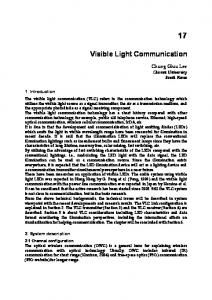
and cutoff shield to shape the light distribution of LED low beam. Fig. 2 shows the designed collimator concept and light distribution of low beam.
In this paper, we propose the simulation modeling of VLC channel for ITS reflecting practical usage scenario. In order to describe the practical VLC channel more precisely, we consider the lighting regulation for transportation such as light distribution for vehicular LED Head Lamp and Street Lamp and other optical properties in designing ITS scenario based on VLC. For simulations, we model the usage scenario by using CATIA V5 tool [13]. Measurements for VLC channel modeling are gathered by using Ray-Tracing scheme with LightTools [14] software, which is a widely verified commercial tool in optical engineering. Finally, the channel impulse response for VLC is evaluated from the measurements and its characteristics are discussed.
(a) Concept of designed collimator
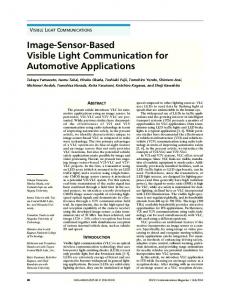
II. MODELING OF VLC CHANNEL ENVIRONMENT A. Modeling of VLC Light Sources for ITS We model two practical LED light sources for VLC in ITS. One is automotive LED headlamp and the other is LED street lamp. LED headlamp is composed of high beam, low beam, turn signal lamp, position lamp, daytime running lamp (DRL) as shown in Fig 1. For more precise modeling, we use practical lamp model as light sources. By using the modeling data of practical LED headlamp, we design the low beam of LED headlamp.
(b) Light distribution concept of LED low beam Figure 2.
Concept and Structure of LED low beam
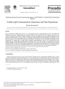
Finally, we designed low beam module at CATIA V5. After setting three collimating optics and two spread optics, we operate optic simulation and the corresponding light distribution is optimized by SPEOS Catia CAA based on EC regulations as shown in Fig. 3. Next, the other practical light source is street lamp. We imported the light distribution of LED street lamp from library of Dialux instead of modeling the real shape of LED street lamp. Figure 4 shows the light distribution data and the simulated light distribution of LED street lamp.
(a) Modeling of LED low beam
Figure 1.
Structure of LED headlamp (Refence Model: Audi R8 headlamp)
Because LED source intensity is lower than the conventional halogen or High Intensity Discharge (HID) lamps, lots of LEDs are needed for equivalent lamp performance. For this reason, LED headlamp consists of multi source and optical components. Furthermore, the size of source and optical components are smaller than conventional lamp. In case of our reference LED headlamp, low beam module has three collimating optics using lens and two spread optics using reflector. Five LEDs are used with projection lens
(b) Simulated light distribution of LED low beam Figure 3.
464
Modeling and light distribution of LED low beam
The second scenario is metropolitan street way which involves longer street road, higher buildings than crossroad, vehicles and street lamps. The second scenario is the most formal ITS service scenario because many vehicles in the urban street really requires several traffic information to enhance the traffic flow more efficiently. Other important service scenario such as high way scene may be easily applied based on metropolitan street scenario. Note that two proposed scenarios consider both vehicle-to-vehicle (V2V) and vehicle-to-infra (V2I) communication link. In the first scenario, we design a scene by using CATIA V5 tools. Then, it is imported to LightTools for optic simulations. After this initial process, optic simulation process is performed as follows. First, set reference cars as a light source and target, traffic lights as detectors, another objects as interference environments. Next, determine parameters to reflect optical characteristics of objects that constitute the scene. As a reflectance parameter of each object for interference effect, we use lambertian reflection property and reflectance to describe more realistic scene. For light sources, we import the light distribution of practical head lamp as discussed in Section 2-1. For evaluating channel model, we use total six scenes (3 for V2V and 3 for V2I communication link) as shown in Fig 6.
(a) Light distribution data
(b) Simulated light distribution Figure 4.
In the second scenario, the initial process is same with the first scenario. In this case, we also deal with V2V and V2I communication link. For V2V link modeling, we set the reference vehicle at first. Then, determine target vehicles in the Field-Of-View (FOV) range of the reference vehicle. In case of V2I link modeling, we set about 4 target vehicles under the reference street lamp after setting reference street lamp. In case of street lamp, we use the light distribution of practical street lamp as shown in Section 2-1. For evaluating channel model, we use total seven scenes (4 for V2V and 3 for V2I communication link) as shown in Fig 7.
The light distribution of LED street lamp
B. Modeling of VLC Usage Scenario for ITS We think that ITS for VLC will be initially deployed in urban area. As a consequence, we choose two VLC usage scenarios for ITS as shown in Fig 5. The first one is a crossroad scenario composed of vehicles in four directions, buildings, roads/fields and traffic lights. Vehicles waiting for the traffic signs in crossroad are possible to exchange information with traffic lights and other vehicles such as traffic information, vehicle condition, etc.
(a) Crossroad Scenario
(b) Metropolitan Street Scenario Figure 5.
(a) Three Scenes for Vehicle-to-Vehicle Communication Link (V2V)
VLC Usage Scenarios for ITS (a) Crossroad Scenario (b) Metropolitan Scenario
465
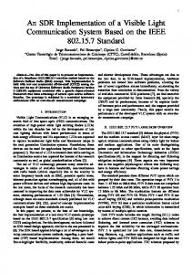
LightTools software tools. Using backward optic ray tracing scheme, we obtain the received optic power and the traveling length of each direct and indirect optic ray. Then, it is converted to channel impulse response. All the channel impulse response is normalized to have unit energy and the propagation delay time is removed to represent the delay spread of each channel. Figure 8 shows total six scenes (three for V2V and three for V2I) in Crossroad scenario and the corresponding channel impulse responses.
(b) Three Scenes for Vehicle-to-Infra (Traffic lights) Communication Link (V2I) Figure 6.
VLC scenes for V2V and V2I communication link in Crossroad Scenario
(a) Three Scenes for V2V communication and corresponding channel impulse responses
(a) Four Scenes for Vehicle-to-Vehicle Communication Link
(b) Three Scenes for V2I communication and corresponding channel impulse responses Figure 8.
In case of V2V communication link, there are dominant multiple LOS paths with negligible multipath components. Therefore, it can be modeled as multiple LOS channel. In case of V2I communication link, there are several LOS ingredients and small number of multipath components. Therefore, it can be modeled as Mixed LOS and Non Line Of Sight (NLOS) channel. Figure 9 shows total seven scenes (four for V2V and three for V2I) in Metropolitan scenario and the corresponding channel impulse responses. As shown in the figure, there are several sub-cases per each scene. This is because we consider all the target vehicles in the Field-Of-View (FOV) range of the reference vehicle and streetlamp. Therefore, each sub-case means the channel impulse response between reference
(b) Three Scenes for Vehicle-to-Infra (Street Lamp) Communication Link Figure 7.
VLC Channel Impulse Responses in Crossroad Scenerio
VLC scenes for V2V and V2I communication link in Metropolitan Scenario.
III. VLC CHANNEL SIMULATION RESULTS We consider two given scenarios (Crossroad and Metropolitan) for VLC channel simulations. For evaluating simulated VLC channel model, we use Catia V5 and 466
vehicle (or street lamp) and each target vehicle in the range of FOV.
(b) Three scenes for V2I communication and corresponding channel impulse Figure 9.
VLC Channel Impulse Responses in Metropolitan Scenerio
In V2V communication link, there are multiple LOS and multipath components with short delay spread. Similarly, V2I channel impulse response is composed of multiple LOS and multipath components with relatively long delay spread than V2V link in some cases. Therefore, we can model V2V and V2I channel impulse response of Metropolitan scenario as Mixed LOS and NLOS channel. Compared with Crossroad case, Metropolitan scenario shows more dispersive VLC channel condition. In addition, V2I link than V2V link has more multipath components and relatively longer delay spread. IV. CONCLUSION Channel models are essential baselines when we evaluate the basic performance of VLC systems through simulations. For the automotive application of VLC such as ITS, we evaluated VLC channel model in the Crossroad and Metropolitan scenarios based on the practical VLC light sources (LED headlamp and Street light). For simulations, we use LightTools and CATIA V5 tools because they are an effective tool to obtain optical channel models providing visual understanding and reflecting practical modeling of simulation environments. Through simulations, we notice that 1) V2I communication links than V2V case in both scenario, and 2) Metropolitan scenario than Crossroad case suffer from more harsh multipath channel condition.
(a) Four scenes for V2V communication and corresponding channel impulse
ACKNOWLEDGMENT This research was supported by Basic Science Research Program through the National Research Foundation of Korea (NRF) funded by the Ministry of Education, Science and Technology (No. 2011-0026560) and also conducted under the industrial infrastructure program for fundamental technologies (No. 10033630) which is funded by the Ministry of Knowledge Economy(MKE, Korea). 467
REFERENCES [1]
[2]
[3]
[4]
[5]
[6]
[7] [8]
[9]
[10]
[11]
[12]
[13]
[14]
T. Komine, et al., "Fundamental Analysis for Visible-Light Communication System using LED lights," IEEE Trans.on Consumer Electron., vol.50, no.1, pp.100-107, Feb. 2004. G. Ntogari, et al., ”Combinig illumination dimming based on pulse-width modulation with Visible-Light Communications based on discrete multitone”, Journ. of IEEE/OSA, vol. 3, no. 1, pp. 56-65, Jan. 2011. IEEE Std 802.15.7, IEEE Standard for Local and metropolitan area networks-Part 15.7: Short-Range Wireless Otical Communication Using Visible Light, IEEE, Piscataway, N.J., 2011. R. Roberts, et al., “ Visible light positioning : Automotive use case”, Vehicular Networking Conference, 2010 IEEE, pp. 309-314, Dec. 2010. M. Yoshino, et al., “ High accuracy position system using visible LED light and image sensor”, Radio and wireless Sym. 2008 IEEE, pp. 439-442, Jan.2008. Y. H. Choi, et al., “ Novel LBS technique based on visible light communication”, ICCE 2012 IEEE International cof. on, pp. 576-577, Jan. 2012. M. Wada, et al., " Road-to-vehicle Communication Using LED Traffic Light", Intelligent Vehicles Sym., 2005. T. Nagura, et al., " Improved Decoding Methods of Visible Light Communication System for ITS Using LED Array and High-Speed Camera", Vehicular Technology Conf. (VTC 2010-Spring), 2010. H. C. N. Premachandra et al.,”High-speed-camera image processing based LED traffic light detection for road-to-vehicle visible light communication,” in Proc. of IEEE Intelligent Vehicles Sym., 2010, pp. 793-798. I. E. Lee, et al., “ Performance enhancement of outdoor visible-light communication system using selective combining receiver”, IET Optoelectronics, vol. 3, no. 1, pp. 30-39, 2009. N. Kumar, et al.,”Visible light communication for intelligent transportation in road safety applications,” in Proc. of IEEE International conf. on Wireless Communications and Mobile Computing Conf., pp. 1513-1518, July 2011. I. E. Lee, et al., “A dual-receiving visible light communication system under time-variant non-clear sky channel for intelligent transportation system”, in Proc. of IEEE European conf. on Network and Optical Communications, pp. 153-156, July 2011. N. A. Davidoff, et al., “A graphic model of the human hand using CATIA”, International Journal of Industrial Ergonomics, vol. 12, issue 4, pp. 255-264, Aug. 1993. M. J. Hayford, et al., “ Characterization of illumination systems using LightTools”, in Proc. of SPIE, vol. 3130, pp.209, 1997.
468