REVIEW PAPER International Journal of Recent Trends in Engineering, Vol 2, No. 4, November 2009
Images and Its Compression Techniques – A Review Sindhu M1, Rajkamal R2 1
Department of Information Technology, Indira Institute of Engineering and Technology, Pandur, Thiruvallur, TN, India,
[email protected] 2 Department of Electrical & Electronics Engineering, Indira Institute of Engineering and Technology, Pandur, Thiruvallur, TN, India,
[email protected] Abstract- The availability of images in different applications are augmented owing to the technological advancement which cannot impacts on several image operation, on availability of sophisticated software tools that manipulate the image and on image management. Despite the technological advances in storage and transmission, the demand placed on the storage capacities and on bandwidth of communication exceeds the availability. Hence, image compression has p r o v e d t o be a valuable technique as one solution. This paper gives the review of types of images and its compression techniques. Based on the review, we recommended some general guidelines to choose the best compression algorithm for an image. Keywords- Image, Image Compression techniques.
I. INTRODUCTION An image is essentially a 2-D signal processed by the human visual system. The signals representing images are usually in analog form. However, for processing, storage and transmission by computer applications, they are converted from analog to digital form. A digital image is basically a 2-Dimensional array of pixels [1]. Images form the significant part of data, particularly in remote sensing, biomedical and video conferencing applications. The use of data depends on information and computers continue to grow, so it does our need for efficient ways of storing and transmitting large amounts of data. In this paper, the term “Image” refers to “Digital Image”. A. Need of Compression In a raw state, images can occupy a large amount of memory both in RAM and in storage. Image compression reduces the storage space required by an Image and the bandwidth needed when streaming that image across a network.
From the Table. I. [2], the examples show clearly the need for sufficient storage space, large transmission bandwidth and long transmission time for image. At the present state of art in technology, the only solution is to compress image. B. Principle of Compression A common characteristic of most of the images is that the neighboring pixels are correlated and therefore contain redundant information. The foremost task is to find less correlated representation of the image. Two fundamental components of compression are redundancy and irrelevancy reduction [3]. Redundancy reduction aims at removing duplication from the signal source (image). Irrelevancy reduction omits parts of the signal that will not be noticed by the signal receiver, namely the Human Visual System (HVS). In general, three types of redundancy can be identified: • Spatial Redundancy or correlation between neighboring pixel values. •
Spectral Redundancy or correlation between different color planes or spectral bands.
•
Temporal Redundancy or correlation between adjacent frames in a sequence of images (in video applications). Since, we focus only on still images. Image compression techniques are explored in this paper. For image compression there are three types of redundancies, 1. Coding Redundancy 2. Interpixel Redundancy 3. Psychovisual Redundancy Coding redundancy is present when less than optimal code words are used. Interpixel redundancy results from correlations between the pixels of an image.
TABLE I. DESCRIBE TYPES OF IMAGES, ITS SIZE, BITS/PIXEL, UNCOMPRESSED SIZE, TRANSMISSION BANDWIDTH AND TIME
Types Of Image
Size/Duration
Bits/Pixel or Bits/Sample
Uncompressed Size (B for Bytes)
Transmission Bandwidth (b for Bits)
Transmission Time (using a 28.8K Modem)
Grayscale Image Color Image Medical Image
512 x 512 512 x 512 2048 x 1680
8 bpp 24 bpp 12 bpp
262 KB 786 KB 5.16 MB
2.1 Mb/Image 6.29 Mb/Image 41.3 Mb/Image
1 min 13 sec 3 min 39 sec 23 min 54 sec
SHD Image
2048 x 2048
24 bpp
12.58 MB
100 Mb/Image
58 min 15 sec
© 2009 ACADEMY PUBLISHER
71
REVIEW PAPER International Journal of Recent Trends in Engineering, Vol 2, No. 4, November 2009 B. GIF Graphics Interchange Format (GIF) is useful for images that have less than 256-(2^8) colors, grayscale images and black and white text. The primary limitation of a GIF is that it only works on images with 8-bits per pixel or less, which means 256 or fewer colors. Most color images are 24 bits per pixel [4]. To store these in GIF format that must first convert the image from 24 bits to 8 bits. GIF is a lossless image file format. Thus, GIF is “lossless” only for images with 256 colors or less. For a rich, true color image, GIF may “lose” 99.998% of the colors. It is not suitable for photographic images, since it can contain only 256 colors per image.
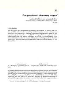
Psychovisual redundancy is due to data that is ignored by the human visual system (i.e. visually non essential information). The objective of image compression is to reduce the number of bits. It needs to represent an image by removing the Spatial and Spectral redundancies as much as possible, while keeping the resolution and visual quality of the reconstructed image as close to the original image by taking advantage of these redundancies. An inverse process called decompression (decoding) is applied to the compressed data to get the reconstructed image. Compression Input Image
C.
Output Image
Mapper
Quantizer
Encoder
Inverse Mapper
Dequantizi er
Decoder
PNG Portable Network Graphics (PNG) is a file format for lossless image compression. Typically, an image in a PNG file can be 10% to 30% more compressed than in a GIF format [4]. It allows to make a trade-off between file size and image quality when the image is compressed. It produces smaller files and allows more colors. PNG also supports partial transparency. Partial transparency can be used for many useful purposes, such as fades and antialiasing for text.
Decompression
D. JPEG Joint Photographic Expert Group (JPEG) is an excellent way to store 24-bit photographic images, such as those used for imaging and multimedia applications. JPEG 24-bit (16 million color) images are superior in appearance to 8-bit (256 color) images on a Video Graphics Array (VGA) display and are at their most spectacular, when using 24-bit display hardware (which is now quite inexpensive) [5]. JPEG was designed to compress, color or gray-scale continuous-tone images of real-world subjects, photographs, video stills, or any complex graphics, that resemble natural subjects. Animations, ray tracing, line art, black-and-white documents, and typical vector graphics don’t compress very well under JPEG and shouldn’t be expected to. And, although JPEG is now used to provide motion video compression, the standard makes no special provision for such an application.
Fig. 1. Image Compression and Decompression
As shown in Fig.1, the encoder is responsible for reducing the coding, interpixel and psychovisual redundancies of input image. In first stage, the mapper transforms the input image into a format designed to reduce interpixel redundancies. The second stage, quantizer block reduces the accuracy of mapper’s output in accordance with a predefined criterion. In third and final stage, a symbol decoder creates a code for quantizer output and maps the output in accordance with the code. These blocks perform, in reverse order, the inverse operations of the encoder’s symbol coder and mapper block. The compression achieved can be quantified numerically via the compression ratio. In this paper, we present a review of various types of image in section II and its compression techniques in section III. In section IV the general guidelines can be followed to compress an image is concluded.
E. JPG JPG is optimized for photographs and similar continuous tone images that contain many, numbers of colors [6]. JPG works by analyzing images and discarding kinds of information that the eye is least likely to notice. It stores information as 24 bit color. The degree of compression of JPG is adjustable. At moderate compression levels of photographic images, it is very difficult for the eye to discern any difference from the original, even at extreme magnification. Compression factors of more than 20 are often acceptable.
II. IMAGE Generally images are classified as the following. A. TIFF The TIFF (Tagged Image File Format) is a flexible format that can be lossless or lossy compression [14]. It normally saves 8 bits or 16 bits per color (red, green, blue) for 24-bit and 48-bit totals, respectively. The details of the image storage algorithm are included as part of the file. In practice, TIFF is used almost exclusively as a lossless image storage format that uses no compression at all. TIFF files are not used in web images. They produce big files, and more importantly, most web browsers will not display TIFFs.
© 2009 ACADEMY PUBLISHER
F.
RAW RAW refers to a family of raw image formats (output) that are options available on some digital cameras [12]. These formats usually use a lossless or nearly-lossless compression, and produce file sizes much smaller than the TIFF formats of full-size processed images from the same cameras. The raw formats are not standardized or
72
REVIEW PAPER International Journal of Recent Trends in Engineering, Vol 2, No. 4, November 2009 involve a linear combination of neighboring pixel values, possibly in conjunction with an edge detection heuristic that attempts to allow for discontinuities in intensities. In the second step, the difference between the predicted pixel value and the actual intensity of the next pixel is coded using an entropy coder and a chosen probability distribution.
documented. Though lossless, it is a factor of three or four smaller than TIFF files of the same image. The disadvantage is that there is a different RAW format for each manufactures and so has to use the manufacturer’s software to view the images. (Some graphics applications can read some manufacturer’s RAW formats.) G. BMP The Bitmap (BMP) file format handles graphics files within the Microsoft Windows OS. Typically, BMP files are uncompressed, hence they are large; advantage is that their simplicity, wide acceptance, and use in Windows program [8].
a.
Run Length Encoding Run length Encoding (RLE) is one of the simplest image compression techniques. It consists of replacing a sequence (run) of identical symbols by a pair containing the symbol and the run length [7]. It is used as the primary compression technique in the 1-D CCITT Group 3 fax standard and in conjunction with other techniques in the JPEG image compression standard.
H. NETPBM Netpbm format is a family including the "Portable Pixel Map" file format (PPM), the "Portable Gray Map" file format (PGM) and the "Portable Bit Map" file format (PBM) [11]. These are either pure ASCII files or raw binary files with an ASCII header that provide very basic functionality and serve as a lowest-common-denominator for converting pixmap, graymap, or bitmap files among different platforms. Several applications refer to them collectively as the "Portable Any Map" (PNM).
b. Statistical Coding The following techniques are included in the statistical coding technique; 1.Huffman Encoding, 2.Arithmetic Encoding and 3.LZW Encoding [9],[10]. 1. Huffman Encoding Huffman coding is based on the frequency of occurrence of a data item (pixel in images). The principle is to use a lower number of bits to encode the data that occurs more frequently. Codes are stored in a Code Book which may be constructed for each image or a set of images. In all cases the code book plus encoded data must be transmitted to enable decoding. In order to encode images: • Divide image up into 8 x 8 blocks • Each block is a symbol to be coded • Compute Huffman codes for set of block • Encode blocks accordingly
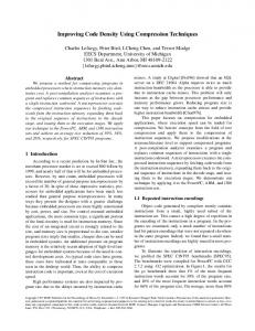
III. COMPRESSION ALGORITHM Compression algorithms come in two general flavors: lossless and lossy. As the name states, when lossless data is decompressed, the resulting image is identical to the original. Lossy compression algorithms result in loss of data and the decompressed image is not exactly the same as the original. A. Lossless Compression In lossless compression scheme, shown in Fig.2 the reconstructed image, after compression, is numerically identical to the original image. However lossless compression can only achieve a modest amount of compression. Lossless compression can reduce it to about half that size, depending on the type of file being compressed. This makes lossless compression convenient for transferring files across the Internet, as smaller files transfer faster. Table Specification
Lossless Encoder
Source Image
2. Arithmetic Coding In this technique, instead of coding each symbol separately, whole image sequence is coded with a single code. Thus, the correlation on neighboring pixels is exploited. Arithmetic coding is based on the following principle. Given that • the symbol alphabet is finite; • all possible symbols sequences of a given length are finite; • all possible sequences are countably infinite; • The number of real numbers in the interval [0, 1] is unaccountably infinite; we can assign a unique subinterval for any given input (sequence of symbols).
Predictor
Entropy Encoder
3. LZW Coding LZW algorithm is working based on the occurrence multiplicity of character sequences in the string to be encoded. Its principle consists in substituting patterns with an index code, by progressively building a dictionary. The dictionary is initialized with the 256 values of the ASCII table. The file to be compressed is split into strings of bytes (thus monochrome images – coded on 1 bit – this compression is not very effective), each of these strings is compared with the dictionary and is added, if not found there. In encoding process the algorithm goes over the stream of information, coding it; if a string is never smaller than the longest word in the
Compressed Image
Fig. 2. Block Diagram for Lossless Compression
Lossless image compression techniques typically consider images to be sequence of pixels in row major order. The processing of each pixel consists of two separate operations. The first step forms a prediction as to the numeric value of the next pixel. Typical predictors
73 © 2009 ACADEMY PUBLISHER
REVIEW PAPER International Journal of Recent Trends in Engineering, Vol 2, No. 4, November 2009 in other words, whatever loss is introduced by the quantizer in the encoder stage is not reversible.
dictionary then it s transmitted. In decoding process, the algorithm rebuilds the dictionary in the opposite direction; it thus does not need to be stored.
b. Block Truncation Coding Block Truncation Coding (BTC) is a technique for grayscale images. It divides the original images into blocks and then uses a quantizer to reduce the number of grey levels in each block while maintaining the same mean and standard deviation. It is an early predecessor of the popular hardware DirectX Texture Compression (DXTC) technique, although BTC compression method was first adapted to color long before DXTC using a very similar approach called Color Cell Compression. Sub blocks of 4 x 4 pixels allow compression of about 25% assuming 8-bit integer values are used during transmission or storage [15]. Larger blocks allow greater compression however quality also reduces with the increase in block size due to the nature of the algorithm.
c. Predictive Coding Predictive Coding Technique constitute another example of exploration of interpixel redundancy, in which the basic idea to encode only the new information in each pixel. This new information is usually defined as the difference between the actual and the predicted value of the pixel. The predictor’s output is rounded to the nearest integer and compared with the actual pixel value: the difference between the two- called prediction error. This error can be encoded by a Variable Length Coding (VLC). The distinctive feature of this method lies in the paradigm used to describe the images. The images are modeled as non-causal random fields, i.e., fields where the intensity at each pixel depends on the intensities at sites located in all directions around the given pixel.
c.
Sub-band Coding The fundamental concept behind Sub-band Coding (SBC) is to split up the frequency band of a signal and then to code each sub-band using a coder and bit rate accurately matched to the statistics of the band [17]. SBC has been used extensively first in speech coding and later in image coding because of its inherent advantages namely variable bit assignment among the subbands as well as coding error confinement within the subbands. At the decoder, the subband signals are decoded, unsampled and passed through a bank of synthesis filters and properly summed up to yield the reconstructed image.
B. Lossy Compression A lossy compression scheme, shown in Fig. 3, may examine the color data for a range of pixels, and identify subtle variations in pixel color values that are so minute that the human eye/brain is unable to distinguish the difference between them [16]. The algorithm may choose a smaller range of pixels whose color value differences fall within the boundaries of our perception, and substitute those for the others. The finely graded pixels are then discarded. Very significant reductions in file size may be achieved with this form of compression, but the sophistication of the algorithm determines the visual quality of the finished product.
Input Image
Source Encoder
Compressed Image
d. Vector Quantization Vector quantization (VQ) techniques extend the basic principles of scalar quantization to multiple dimensions. This technique is to develop a dictionary of fixed-size vectors, called code vectors. A given image is then partitioned into non-overlapping blocks called image vectors. Then for each image vector, the closest matching vector in the dictionary is determined and its index in the dictionary is used as the encoding of the original image vector [18]. Because of its fast lookup capabilities at the decoder side, VQ-based coding schemes are particularly attractive to multimedia applications.
Quantizer
Entropy Encoder
Fig.3. Block Diagram for Lossy Compression
e.
Fractal Compression The fractal compression technique relies on the fact that in certain images, parts of the image resemble other parts of the same image. Fractal algorithms convert these parts, or more precisely, geometric shapes into mathematical data called "fractal codes" which are used to recreate the encoded image. Once an image has been converted into fractal code its relationship to a specific resolution has been lost; it becomes resolution independent. The image can be recreated to fill any screen size without the introduction of image artifacts or loss of sharpness that occurs in pixel-based compression schemes.
a. Transform Coding Transform coding algorithm usually start by partitioning the original image into sub images (blocks) of small size (usually 8 x 8). For each block the transform coefficients are calculated, effectively converting the original 8 x 8 array of pixel values into an array of coefficients closer to the top-left corner usually contain most of the information needed to quantize and encode the image with little perceptual distortion [14]. The resulting coefficients are then quantized and the output of the quantizer is used by a symbol encoding technique(s) to produce the output bit stream representing the encoded image. At the decoder’s side, the reverse process takes place, with the obvious difference that the ‘dequantization’ stage will only generate an approximated version of the original coefficient values;
IV. CONCLUSION Based on the review of images and its compression algorithms we conclude that the compression normally chosen for compressing the images needs to be
74 © 2009 ACADEMY PUBLISHER
REVIEW PAPER International Journal of Recent Trends in Engineering, Vol 2, No. 4, November 2009 experimented with the various compression methods on various types of images. The following general guidelines can be applied as a starting point to compress images: • For true (photographic) images that do not require perfect reconstruction when decompressed, the JPEG compression can be used. • For screen dumps, FAX images, computergenerated images, or any image that requires perfect reconstruction when decompressed, the LZW compression can be used. The best algorithm is measured depends on the following 3 factors: • The quality of the image • The amount of compression • The speed of compression.
[3].
[4].
[5]. [6]. [7]. [8].
[9]. [10].
Quality of the Image The quality of an image after being compressed depends on usage of two kinds of compression such as: • Lossless compression • Lossy compression
[11].
Amount of Compression The amount of compression depends on both the compression method and the content of the image.
[14].
[12]. [13].
[15].
Speed of Compression The speed of image compression and decompression depends on various factors such as the type of file, system hardware, and compression method.
[16].
[17].
Future Image Compression Standard In future Image Compression standard is intended to advance standardized image coding systems to serve applications into the next millennium. It has to provide a set of features vital to many high-end and emerging image applications by taking advantage of new modern technologies. Specifically, the new standard will address areas where current standards fail to produce the best quality or performance. It will also provide capabilities to markets that currently do not use compression. New standard will strive for openness and royalty-free licensing. It has to be intended to compliment, not replace, the current JPEG standards. In future, the image compression will include many modern features including improved low bit-rate compression performance, lossless and lossy compression, continuoustone and bi-level compression of large images, single decompression architecture, transmission in noisy environments including robustness to bit-errors, progressive transmission by pixel accuracy and resolution, content-based description, and protective image security.
[18].
REFERENCES [1].
[2].
Subramanya A. “Image Compression Technique,” potentials IEEE, Vol. 20, issue 1, pp19-23, Feb-March 2001. Jeffrey M. Gilbert, Robert W. Brodersen; “A Lossless 2D Image Compression Technique for Synthetic DiscreteTone Images”. University of California at Berkeley,
75 © 2009 ACADEMY PUBLISHER
Electrical Engineering & Computer Sciences Berkeley, CA 94720-1770, Unpublished. Subhasis Saha; “Image Compression – from DCT to Wavelets: A Review”, Unpublished http://www/acm/org/crossroads/xrds63/sahaimgcoding.html. “Understanding Image Types” http://www.contentdm.com/USC/tutorial/image-filetypes.pdf.1997-2005,DiMeMa,Inc, Unpublished. http://www.find-images.com http://www.wfu.edu Majid Rabbani, Paul W.Jones; “Digital Image Compression Techniques”. Edition-4, 1991.page 51. John Miano; “Compressed image file formats: JPEG, PNG, GIL, XBM, BMP”, Edition-2, January-2000, page 23. Ronald G. Driggers; “Encylopedia of optical engineering”, Volume 2, Edition 1,2003. Ioannis Pitas; “Digital image processing algorithms and applications.”, ISBN 0-471-37739-2. Cameron Newham, Bill Rosenblatt; “Learning the bash Shell”, Edition 3, 2005. Rod Sheppard; “Digital Photoraphy”, Edition 3,2007, page 10. Deke McClelland, Galen Fott; “Photoshop elements 3 for dummies”, Edition 1, 2002, page 126. Keshab K. Parhi, Takao Nishitan; “Digital Signal processing for multimedia systems”, ISBN 0-8247-19247, United States of America, page 22. Majid Rabbani, Paul W. Jones; “Digital image compression techniques”; ISBN 0-8194—0648-1, Washington, page 129. Vasudev Bhaskaran, Konstantinos Konstantinides; “Image and video compression standards: algorithms and architectures”. Edition 2, 1997, page 61. Rafael C. Gonzalez, Richard Eugene; “Digital image processing”, Edition 3, 2008, page 466. Alan Conrad Bovik; “Handbook of image and video processing”, Edition 2 1005, page 673.