This article has been accepted for publication in a future issue of this journal, but has not been fully edited. Content may change prior to final publication. Citation information: DOI 10.1109/JEDS.2016.2618425, IEEE Journal of the Electron Devices Society IEEE JOURNAL OF THE ELECTRON DEVICES SOCIETY, VOL. X, NO. Y, AUGUST 2016
1
Impact of the incremental programming algorithm on the filament conduction in HfO2 based RRAM arrays Eduardo P´erez, Alessandro Grossi, Cristian Zambelli, Piero Olivo, and Christian Wenger
Abstract—In this work, the Set operation of HfO2 based 1T-1R arrays is studied by applying incremental step pulse with verify algorithm (ISPVA). To evaluate the impact of the voltage step increment on the conduction mechanism of filaments, the voltage increments between consecutive pulses are varied between 0.05 and 0.4 V. The extracted leakage values after the Set operation were discussed in the framework of the quantum point contact model (QPC). In the so called low resistive state (LRS), the conductive filaments (CF) demonstrate a defined signature of conductance quantization. Index Terms—RRAM, HfO2 , QPC model, programming algorithm
I. I NTRODUCTION ESISTIVE Random Access Memories (RRAM) based on HfO2 is one of the most promising technology candidates for replacing Flash memories [1], [2]. This technology has shown fast low-power switching operations, high-integration density [3], [4], and compatibility with CMOS processes [5]. However, an intensive research activity has still to be performed on this innovative technology in order to increase RRAM reliability and performance. After the concept validation on single cells [6], [7], the characterization of array structures is mandatory to bring such technology to a maturity level [8]–[10]. RRAM behavior is based on the electrical modification of the conductance of a Metal-Insulator-Metal (MIM) stack: the Set operation moves the cell into a Low Resistive State (LRS), whereas Reset operation brings the cell back to a High Resistive State (HRS) [8], [11]. In order to control the formation and rupture of the conductive filament (CF), the Incremental Step Pulse with Verify Algorithm (ISPVA) [12]– [14] is applied instead of a simple DC voltage sweep [15]. The drawback of ISPVA guided Set and Reset operations is the increased power consumption per writing cycle. One way to minimize the consumption is to enlarge the incremental voltage steps. For this purpose, a complete study of the voltage increment variation between consecutive pulses on array
R
E. P´erez, and C. Wenger are with IHP GmbH/Leibniz-Institut fur innovative Microelektronik, Im Technologiepark 25, 15236 Frankfurt (Oder), Germany (e-mail:
[email protected]). A. Grossi, C. Zambelli, and P. Olivo are with Dip. di Ingegneria, Universit´a degli Studi di Ferrara, Via G. Saragat 1, 44122 Ferrara, Italy This work was supported by the European Union’s H2020 research and innovation programme under grant agreement No 640073. This work was supported by ENIAC Joint Undertaking 2013-2, PANACHE No. 621217. The publication of this article was funded by the Open Access Fund of the Leibniz Association.
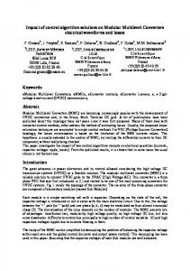
Fig. 1. Simplified block diagram of the 4 kbits memory device.
RRAM devices was performed. The extracted experimental results were analyzed in the framework of the quantum point contact (QPC) model [16]. II. S AMPLES CHARACTERISTICS The measurements were performed over 4 kbits memory devices organized in 64 pages (rows) each consisting of 64 cells (bits), as Fig. 1 shows including also the peripheral circuitry. Each cell is a 1T-1R RRAM single device constituted by a select NMOS transistor manufactured in 0.25 µm BiCMOS technology: W = 1.14 µm and L = 0.24 µm. Such a transistor also sets the current compliance, whose drain is in series to a variable resistor connected to the bitline (BL). The variable resistor is a Metal-Insulator-Metal (MIM) device integrated on the metal line 2 of the CMOS process. The schematic and cross-sectional SEM image of the integrated RRAM cell including the metal lines and the W based Via-connections are shown in Fig. 2. The MIM resistor is a TiN/HfO2 /Ti/TiN stack of 150 nm TiN layers deposited by magnetron sputtering, a 7 nm Ti layer (under TiN top electrode), and a 8 nm HfO2 layer grown by Chemical Vapor Deposition (CVD), which results in amorphous films (determined by X-Ray Diffraction measurements). The resistor area is equal to 0.4 µm2 . III. E XPERIMENTAL RESULTS AND DISCUSSION The electrical characteristics were obtained by means of a set-up based on the RIFLE SE test system working together with the Cascade PA200 semi-automatic probe system. In
2168-6734 (c) 2016 IEEE. Translations and content mining are permitted for academic research only. Personal use is also permitted, but republication/redistribution requires IEEE permission. See http://www.ieee.org/publications_standards/publications/rights/index.html for more information.
This article has been accepted for publication in a future issue of this journal, but has not been fully edited. Content may change prior to final publication. Citation information: DOI 10.1109/JEDS.2016.2618425, IEEE Journal of the Electron Devices Society IEEE JOURNAL OF THE ELECTRON DEVICES SOCIETY, VOL. X, NO. Y, AUGUST 2016
2
Fig. 2. Schematic and cross-sectional SEM image of the integrated RRAM cell.
C u m u la tiv e d is tr ib u tio n [% ]
1 0 0 H R S
8 0 6 0
L R S
4 0
0 .0 0 .1 0 .2 0 .4
2 0 0
(a )
0
5
1 0
1 5
2 0
2 5 3 0 I [m A ]
3 5
4 0
4 5
5 V V V V
5 0
5 5
Fig. 3. Schematic illustration of the Incremental Step Pulse with Verify Algorithm (ISPVA).
0 .9 5
0 .9 0
0 .8 5 (b )
1 0 0 C u m u la tiv e d is tr ib u tio n [% ]
S e t v o lta g e s [V ]
1 .0 0
8 0
0 .0
0 .1 0 .2 0 .3 V o lta g e S te p In c r e m e n t [V ]
0 .4
Fig. 5. Cumulative distribution of read currents (a) and average and dispersion of Set voltages (b) as function of voltage step increment.
6 0 4 0 2 0 0 0
5
1 0
1 5
2 0
2 5 3 0 I [m A ]
3 5
4 0
4 5
5 0
5 5
Fig. 4. Cumulative distribution of the read currents after Forming operation in the 4 subsections of the 4 kbit memory array.
order to ensure a reliable accuracy for statistical calculations 128 1T-1R cells (two 64-bits pages) were characterized at each voltage step. The ISPVA technique consists of a sequence of increasing voltage pulses (Fig. 3) on the BL during Set operation, whereas this sequence is applied on the source line (SL) during Reset operation: Vpulse = 0.2 - 3.5 V, tpulse = 10 µs, tf all/rise = 1 µs. In order to analyze its effect over the RRAM cells behavior, several measurements were done using different voltage step values between consecutive pulses (Vstep ): 0.05, 0.1, 0.2 and 0.4 V. The applied transistor gate voltage values through the wordline (WL) were 2.7 V for Reset and 1.4 V for Set. After every pulse a Read-verify operation is performed with VW L = 1.4 V, Vread = 0.2 V (applied over the Drain) for 10 µs. When the Read current reaches the target value of 18 µA the Set operation is stopped, whereas the Reset operation is stopped when the target value of 6 µA is achieved. To activate the resistive switching behavior, the RRAM cells require a preliminary Forming operation [4]–[7]. This initial operation plays a fundamental role in determining the subsequent devices performance [17]. Therefore, the ISPVA procedure is also used for the Forming operation with the same parameters for each subsection (128 cells) of the 4 kbit
array: Vpulse = 2 - 5 V, tpulse = 10 µs, tf all/rise = 1 µs, Vstep = 0.01 V and VW L = 1.4 V. The cumulative distributions of the currents after forming are within the variability limit of the RRAM process technology as shown in Fig. 4. Therefore, the starting point for the following Reset/Set operations is similar for every subsection. First of all, the impact of the ISPVA procedure on the filamentary conduction mechanism after the first Reset and Set operation was evaluated. As shown in Fig. 5(a), the first Reset operation is not affected by the variation of voltage steps. The currents in the High Resistive State (HRS) are quite similar within the limit of process variability. In contrast to the Reset operation, the currents in the Low Resistive State (LRS) are strongly affected by the increase of voltage increment. At small step increments, 80-90 % of cells are set to the same LRS current values as after the Forming procedure. The remaining 10-20 % cells tend to be set to higher current values. This trend is strongly pronounced at larger incremental voltage steps. Now, 40 % of the cells show a second contribution of LRS currents with much higher values. As illustrated in Fig. 5(b), the Set operations with small voltage increments happen at voltages around 0.85 V. Caused by the increase of the voltage increment to 0.2 and 0.4 V the cells are forced to Set around 1 V. In order to illustrate the distribution of LRS currents in a better way, the Set currents are plotted separately as function voltage step increment in Fig. 6. As shown in Fig. 6(b) and (c), a second peak occurs at about 48 µA. The first peak at about 24 µA is strongly reduced. It is obvious, that a kind of quantization of the conduction mechanism occurs at larger voltage step increments. The observation of conductance quantization in oxide-based
2168-6734 (c) 2016 IEEE. Translations and content mining are permitted for academic research only. Personal use is also permitted, but republication/redistribution requires IEEE permission. See http://www.ieee.org/publications_standards/publications/rights/index.html for more information.
This article has been accepted for publication in a future issue of this journal, but has not been fully edited. Content may change prior to final publication. Citation information: DOI 10.1109/JEDS.2016.2618425, IEEE Journal of the Electron Devices Society IEEE JOURNAL OF THE ELECTRON DEVICES SOCIETY, VOL. X, NO. Y, AUGUST 2016
2 0
3
0 .0 5 V
1 8
4 0 L R S C u rr e n t [m A ]
n u m b e r o f c e lls
1 6 1 4 1 2
1 0 8 6 4 2 0 (a ) 1 5
2 0
2 5
3 0
3 5 4 0 I [m A ]
4 5
5 0
R
-0 .6
5 5 0 .1 V
-0 .4
-0 .2
0 .0 0 .2 V o lta g e [V ]
= 1 .0 1 = 2 k W
0 .4
0 .6
Fig. 7. Experimental (black solid circles) and theoretical I-V characteristics for the LRS in DC mode. The QPC model was used for the theoretical curve (red solid line).
1 6 n u m b e r o f c e lls
N
-4 0
1 8 1 4 1 2
1 0 8 6 4 2 0 (b ) 1 5
2 0
2 5
3 0
3 5 4 0 I [m A ]
4 5
5 0
2 0
5 5 0 .2 V
1 8
Fig. 8. Schematic illustration of the conduction quantization in LRS: (a) one CF with a mean current of about 24 µA and (b) two CF with mean currents of about 48 µA.
1 6 n u m b e r o f c e lls
0
-2 0
2 0
1 4 1 2
1 0 8 6 4 2 0 1 5 (c )
2 0
2 5
3 0
3 5 4 0 I [m A ]
4 5
5 0
2 0
5 5 0 .4 V
1 8 1 6 n u m b e r o f c e lls
2 0
1 4 1 2
1 0 8 6 4 2 0 (d ) 1 5
2 0
2 5
3 0
3 5 4 0 I [m A ]
4 5
5 0
5 5
Fig. 6. Distribution of currents after Set operation as function of voltage step increment: 0.05 V (a), 0.1 V (b), 0.2 V (c) and 0.4 V (d).
resistive memory cells was reported by Zhu et al. [18]. The conductance quantization behavior was attributed to the creation and annihilation of atomic scaled CF in the oxide layer. Later on Lian et al. [19] linked the conduction quantization with the quantum point contact model. Regarding the HfO2 based RRAM cells, a CF is constructed by the Forming operation and its behavior can be explained by the QPC model. Focusing on the LRS, the current raises linear with applied voltage and can be expressed as [20]: I = N G0 V /(1 + N G0 R)
(1)
where G0 = 2e2 /h is the quantum conductance unit, N is the
number of CF and R is a series resistance external to the constriction of the filament. In order to evaluate the number of CF, additional DC measurements were performed, by using the same voltage values as in the ISPVA mode. Fig. 7 illustrates the experimental LRS I-V characteristics. The obtained I-V curve can be explained by the QPC model: the continuous line illustrates the fitting curve for LRS by using (1). The series resistance R is mainly generated by the select transistor and is determined by a separate simulation. The theoretical curve agrees with the experimental data, indicating that the QPC model is able to explain the conduction mechanism. According to the model, one CF is formed (N = 1.01) by applying the adopted ISPVA voltage values. By using the quantum conductance value of 12.9 kΩ at the readout voltage of 0.2 V, the calculated current per filament is about 15 µA, without taking into account external resistances. Although at small incremental steps the first peak appears at about 24 µA, we can assume that just one filament is formed by the Set process at 0.85 V (Fig. 8(a)). According to Grossi et al. [21] G0 value correspond to the bottom limit of the filament conduction: narrower filament implies the creation of a constriction and higher conduction values are caused by enlarged filaments. Since at large incremental steps the second peak appears at about 48 µA, we can conclude that the Set operation at 1.0 V results in the formation of two filaments, as illustrated in Fig. 8(b). It has to be mentioned, that the formation of two filaments is enabled by the saturation current of the select transistor of about 100 µA at the used gate voltage of 1.4 V during the Set process. Finally, the stability of both LRS states and the HRS are
2168-6734 (c) 2016 IEEE. Translations and content mining are permitted for academic research only. Personal use is also permitted, but republication/redistribution requires IEEE permission. See http://www.ieee.org/publications_standards/publications/rights/index.html for more information.
This article has been accepted for publication in a future issue of this journal, but has not been fully edited. Content may change prior to final publication. Citation information: DOI 10.1109/JEDS.2016.2618425, IEEE Journal of the Electron Devices Society IEEE JOURNAL OF THE ELECTRON DEVICES SOCIETY, VOL. X, NO. Y, AUGUST 2016
5 5 5 0 4 5 4 0
L R S
I [m A ]
3 5 3 0 2 5 2 0 1 5 1 0 5 0 1
H R S 1 0
1 0 0 C y c le #
1 k
1 0 k
Fig. 9. Stability of the two LRS states and the HRS during endurance cycling procedure over 11 of the considered devices.
examined by endurance cycling of 104 times using ISPVA. In Fig. 9 are shown the results for 11 of the considered devices. The LRS state consisting just on one CF is stable, while the cells consisting on two CFs demonstrate partially unstable switching behavior, because one or alternative two filaments are involved in the switching process. The conduction through either one or two filaments after Set operations depends on random phenomena as [22] claims. In contradiction to the widely acknowledged picture of filament growth from the active electrode toward the inert electrode, an additional filament growth mode with opposite direction is reported by Dirkmann et al. [22]. HRS current values remains below the threshold value of 6 µA emphasizing the presence of a constriction in the conduction path in the HRS state, as predicted by the QPC model [21].
IV. C ONCLUSION The conduction properties of resistive switching filaments have been studied in HfO2 based memory arrays. By applying the Incremental Step Pulse with Verify Algorithm with varied incremental voltage steps, a quantization of the LRS state is observed in the Set operation regime. The quantization of two LRS conductance states is explained by the QPC model. The endurance study of both conductance states reveals that the conduction path consisting of just one filament is stable, while the one consisting of two filaments is partially unstable.
R EFERENCES [1] Q. Lv, S. Wu, J. Lu, M. Yang, P. Hu, and S. Li, “Conducting nanofilaments formed by oxygen vacancy migration in Ti/TiO2 /TiN/MgO memristive device,” J. Appl. Phys., vol. 110, p. 104511, 2011. [2] S. Nigo, M. Kubota, Y. Harada, T. Hirayama, and S. Kato, “Conduction band caused by oxygen vacancies in aluminum oxide for resistance random access memory,” J. Appl. Phys., vol. 112, p. 033711, 2012. [3] H.-Y. Lee, P.-S Chen, C.-C. Wang, S. Maikap, P.-J. Tzeng, C.-H. Lin, L.-S. Lee, and M.-J. Tsai, “Low-power switching of nonvolatile resistive memory using hafnium oxide,” Jpn. J. Appl. Phys., vol. 46, no. 4B, pp. 2175–2179, Apr. 2007. [4] Y.S. Chen, H.Y. Lee, P.S. Chen, P.Y. Gu, C.W. Chen, W.P. Lin, W.H. Liu, Y.Y. Hsu, S.S. Sheu, P.C. Chiang, W.S. Chen, F.T. Chen, C.H. Lien, M.-J. Tsai, “Highly scalable hafnium oxide memory with improvements of resistive distribution and read disturb immunity,” in Proc. IEEE Int. Electron Devices Meeting (IEDM), Dec. 2009, pp. 1–4.
4
[5] B. Govoreanu, G.S. Kar, Y-Y. Chen, V. Paraschiv, S. Kubicek, A. Fantini, I.P. Radu, L. Goux, S. Clima, R. Degraeve, N. Jossart, O. Richard, T. Vandeweyer, K. Seo, P. Hendrickx, G. Pourtois, H. Bender, L. Altimime, D.J. Wouters, J.A. Kittl, M. Jurczak, “10x10nm2 Hf/HfOx crossbar resistive RAM with excellent performance, reliability and low-energy operation,” in IEEE Int. Electron Devices Meeting (IEDM), Dec. 2011. [6] Y.Y. Chen, B. Govoreanu, L. Goux, R. Degraeve, A. Fantini, G.S. Kar, D.J. Wouters, G. Groeseneken, J.A. Kittl, M. Jurczak, and L. Altimine, “Balancing set/reset pulse for >1010 endurance in HfO2 /Hf 1T1R bipolar RRAM,” IEEE Trans. Electron Dev., vol. 59, pp. 3243–3249, Dec. 2012. [7] Y.Y. Chen, R. Degraeve, S. Clima, B. Govoreanu, L. Goux, A. Fantini, G.S. Kar, G. Pourtois, G. Groeseneken, D.J. Wouters, and M. Jurczak, “Understanding of the endurance failure in scaled HfO2 -based 1T1R RRAM through vacancy mobility degradation,” in IEEE Int. Electron Devices Meeting (IEDM), Dec. 2012, pp. 20.3.1–20.3.4. [8] C. Zambelli, A. Grossi, P. Olivo, D. Walczyk, T. Bertaud, B. Tillack, T. Schroeder, V. Stikanov, and C. Walczyk, , “Statistical analysis of resistive switching characteristics in ReRAM test arrays,” in IEEE Int. Conf. on Microelectronics Test Structures (ICMTS), Mar. 2014, pp. 27– 31. [9] C. Zambelli, A. Grossi, P. Olivo, D. Walczyk, J. Dabrowski, B. Tillack, T. Schroeder, R. Kraemer, V. Stikanov, and C. Walczyk, “Electrical characterization of read window in ReRAM arrays under different SET/RESET cycling conditions,” in Proc. IEEE Int. Memory Workshop (IMW), 2014. [10] A. Grossi, D. Walczyk, C. Zambelli, E. Miranda, P. Olivo, V. Stikanov, A. Feriani, J. Sune, G. Schoof, R. Kraemer, B. Tillack, A. Fox, T. Schroeder, C. Wenger, and C. Walczyk, “Impact of intercell and intracell variability on forming and switching parameters in RRAM arrays,” IEEE Trans. Electron Dev., vol. 62, pp. 2502–2509, Aug. 2015. [11] A. Grossi, P. Olivo, E. Miranda, V. Stikanov, T. Schroeder, C. Walczyk, and C. Wenger, “Relationship among current fluctuations during forming, cell-to-cell variability and reliability in RRAM arrays,” in IEEE Int. Memory Workshop (IMW), May 2015, pp. 1–4. [12] F.T. Chen, H.Y. Lee, Y.S. Chen, Y.Y. Hsu, L.J. Zhang, P.S. Chen, W.S. Chen, P.Y. Gu, W.H. Liu, S.M. Wnag, C.H. Tsai, S.S. Sheu, M.J. Tsai, R. Huang, and S. Iess, “Resistance switching for RRAM applications,” Sci. China Inf. Sci., vol. 54, no. 5, pp. 1073–1086, May 2011. [13] K. Higuchi, T. Iwasaki, and K. Takeuchi, “Investigation of verifyprogramming methods to achieve 10 million cycles for 50nm HfO2 ReRAM,” in IEEE Int. Memory Workshop (IMW), May 2012, pp. 1–4. [14] A. Grossi, E. Perez, C. Zambelli, P. Olivo, and C. Wenger, “Performance and reliability comparison of 1T-1R RRAM arrays with amorphous and polycrystalline HfO2 ,” in Proc. Int. EUROSOI Workshop, Jan. 2016, pp. 80–83. [15] A. Grossi, C. Zambelli, P. Olivo, E. Miranda, V. Stikanov, C. Walczyk, and C. Wenger, “Electrical characterization and modeling of pulse-based forming techniques in RRAM arrays,” Solid State Electron., vol. 115, pp. 17–25, Jan. 2016. [16] E.A. Miranda, C. Walczyk, C. Wenger, and T. Schroeder, “Model for the resistive switching effect in HfO2 MIM structures based on the transmission properties of narrow constrictions,” IEEE Int. Electron Devices Lett., vol. 31, pp. 609–611, Jun. 2010. [17] G. Bersuker, D.C. Gilmer, D. Veksler, P. Kirsch, L. Vandelli, A. Padovani, L. Larcher, K. McKenna, A. Shluger, V. Iglesias, M. Porti, and M. Nafra, “Metal oxide resistive memory switching mechanism based on conductive filament properties,” J. Appl. Phys., vol. 110, p. 124518, 2011. [18] X. Zhu, W. Su, Y. Liu, B. Hu, L. Pan, W. Lu, J. Zhang, and R.W. Li, “Observation of conductance quantization in oxide-based resistive switching memory,” Adv. Mater., vol. 24, pp. 3941–3946, Jun. 2012. [19] X. Lian, S. Long, C. Cagli, J. Buckley, E. Miranda, M. Liu, and J. Sune, “Quantum point contact model of filamentary conduction in resistive switching memories,” in IEEE conference proceedings Ultimate Integ. Silicon (ULIS), Mar. 2012, pp. 101–104. [20] L.M. Procel, L. Trojman, J. Moreno, F. Crupi, V. Maccaronio, R. Degraeve, L. Goux, and E. Simoen, “Experimental evidence of the quantum point contact theory in the conduction mechanism of bipolar HfO2-based resistive random access memories,” J. Appl. Phys., vol. 114, p. 074509, 2013. [21] A. Grossi, C. Zambelli, P. Olivo, E. Miranda, V. Stikanov, T. Schroeder, C. Walczyk, and Ch. Wenger, “Relationship among current fluctuations during forming, cell-to-cell variability and reliability in RRAM arrays,” in Proc. IEEE Int. Memory Workshop (IMW), 2015.
2168-6734 (c) 2016 IEEE. Translations and content mining are permitted for academic research only. Personal use is also permitted, but republication/redistribution requires IEEE permission. See http://www.ieee.org/publications_standards/publications/rights/index.html for more information.
This article has been accepted for publication in a future issue of this journal, but has not been fully edited. Content may change prior to final publication. Citation information: DOI 10.1109/JEDS.2016.2618425, IEEE Journal of the Electron Devices Society IEEE JOURNAL OF THE ELECTRON DEVICES SOCIETY, VOL. X, NO. Y, AUGUST 2016
[22] S. Dirkmann, M. Ziegler, M. Hansen, H. Kohlstedt, J. Trieschmann, and T. Mussenbrock, “Kinetic simulation of filament growth dynamics in memristive electrochemical metallization devices,” J. Appl. Phys., vol. 118, p. 214501, 2015.
5
Christian Wenger received the Diploma in physics from the University of Konstanz, in 1995 and the Ph.D. degree from the Technical University of Dresden, in 2000. Since 2002, he has been with the Innovations for High Performance Microelectronics (IHP), where he works in the field of functional devices for medical and space applications. In 2009, he received the post-doctoral degree at TU Dresden. He has authored and co-authored more than 150 papers and holds 6 patents.
Eduardo P´erez received the M.Sc. and Ph.D. degrees in information and communications technologies from University of Valladolid, Valladolid, Spain, in 2010 and 2014, respectively. He has been with the Innovations for High Performance Microelectronics (IHP) since 2015, where he works in the field of electrical characterization of resistive switching devices.
Alessandro Grossi received the M.Sc. degree in electronic and telecommunications engineering from the Universit´a degli Studi di Ferrara, Ferrara, Italy, in 2013, where he is currently pursuing the Ph.D. degree in engineering science with the Department of Engineering.
Cristian Zambelli received the M.Sc. and the Ph.D. degrees (with honors) in electronic engineering from the University of Ferrara, Ferrara, Italy, in 2008 and 2012, respectively. Since 2015, he holds an Assistant Professor position with the same institution. His current research interests include the electrical characterization, physics, and reliability modeling of different nonvolatile memories such as NAND/NOR Flash, Phase Change Memories, Nano-MEMS memories, Resistive RAM (RRAM), and Magnetic RAM. He is also interested in the evaluation of the Solid State Drives reliability/performance trade-offs exposed by the integrated memory technology.
Piero Olivo received the Ph.D. in electronic engineering from the University of Bologna, Bologna, Italy, in 1987. He has been a Full Professor of Electronics with the University of Ferrara, Ferrara, Italy, since 1994. He is coauthor of the first paper describing and analyzing Stress Induced Leakage Current (SILC) in thin oxides, presented at IRPS ’87. His research interests include the physics, the reliability and the experimental characterization of innovative non-volatile memory cells and architectures.
2168-6734 (c) 2016 IEEE. Translations and content mining are permitted for academic research only. Personal use is also permitted, but republication/redistribution requires IEEE permission. See http://www.ieee.org/publications_standards/publications/rights/index.html for more information.