INTERNATIONAL JOURNAL OF CIVIL AND STRUCTURAL ENGINEERING Volume 1, No 3, 2010 © Copyright 2010 All rights reserved Integrated Publishing services
Research article
ISSN 0976 – 4399
Impedance based Concrete Monitoring using Embedded PZT Sensors Venu Gopal Madhav Annamdas 1, 2 , Yaowen Yang 3 , Chee Kiong Soh 3 1 – Faculty, Department of Civil Engineering, Birla Institute of Technology and Science (BITS), Pilani, Hyderabad Campus, Hyderabad 2 – Visiting Scientist, School of Civil & Environmental engineering, Nanyang Technological University, Singapore, 639798 3 – Faculty, School of Civil & Environmental engineering, Nanyang Technological University, Singapore, 639798
[email protected] ABSTRACT This paper presents a health monitoring study of concrete specimens using embedded piezoelectric transducer (PZT) via electromechanical (EM) impedance technique. The main objective of this research is to present a very easy method of embedding PZT sensor in concrete for monitoring either fresh or cured concrete. The basic principle; is to record EM admittance signatures resulted from the actuations of PZT in the presence of electric field. Any deviations in these signatures during the monitoring period indicate disturbance/ damage in the concrete structure. The PZT can be either surface bonded or embedded, however the important features of embedding PZT inside the host structure are durability and protection from surface finish, vandalism etc. The embedment of PZT in the structure is not as simple as surface bonding because there are several issues such as bonding between PZT and host structure. Moreover, it should withstand the curing pressures and temperatures of the host material, etc. The PZT was found to be more effective for metals as compared to non metals like concrete. Thus, this paper presents a double protection wrap method employing both metal and non metal, where the first protection is provided by a steel wire mesh and the second is by cement paste. The wire mesh serves as bonding connector between the host structure and the PZT, where as cement paste provides connection between concrete and mesh. The implementation was verified on various lab sized concrete cubes and the observations were examined by statistical analysis. Key words: Concrete, monitoring, damage, curing, PZT, root mean square deviation. 1. Introduction In the modern world, health monitoring of engineering structures are gaining importance to preempt failure. Structural Health Monitoring (SHM) of homogeneous materials is simpler as compared to non homogeneous materials like concrete. However, most of the civil engineering constructions are based on non homogeneous concrete. Moreover, monitoring of concrete structures has many potential issues ranging from bonding of monitoring sensors/ systems on concrete to sensing abilities of such systems. Thus, this paper presents electromechanical (EM) impedance based monitoring method using robust embedded smart piezoelectric (PZT) sensor. This method employs PZT as both actuator and sensor either bonded on the surface or embedded inside the host structure. The governing principle is that the PZT sensor actuates harmonically in the presence of electric field to produce a structural response, known as ‘EM admittance signature’. In other words, it is plot of output values of admittance (conductance or susceptance) for considered frequency of excitation of PZT. The admittance signature is a function of the stiffness, mass and damping of the host structure,
414
INTERNATIONAL JOURNAL OF CIVIL AND STRUCTURAL ENGINEERING Volume 1, No 3, 2010 © Copyright 2010 All rights reserved Integrated Publishing services
Research article
ISSN 0976 – 4399
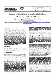
and the length, width, thickness and orientation of the PZT sensor. Any changes in the signature, is indicative of the presence of structural damages. However, the PZT’s performance is not the same for all types of host structures to be monitored. In the recent past, it was established that the PZT activeness is proportional to the host structural material properties. The term activeness refers to the signature accuracies. The PZT activeness can be arranged from higher to lower respectively for metal, concrete, timber/rubber etc. Figure 1 shows the difference in signature generated by PZT, when interacted with two extreme cases i.e wood and steel host structure (representative signature).
Figure 1: Electromechanical signatures of (a) wood (b) metal plate This paper demonstrates the usage of two different materials as host to PZT. i.e the PZT is wrapped by both materials (steel and cement), so that the net activeness of PZT lies between them. Thus assembly of two materials and PZT is named as robust embeddable PZT patch and was used for monitoring concrete specimens. It is much simpler to bond PZT on the host structure; however the important features of embedment are durability and protection from surface finish, vandalism etc . In addition, they do not interfere with the aesthetic beauty of the structure. This paper highlights the issues involved with embedded PZT sensor and proposes a double protection wrap covers with wire mesh method of embedding PZT in concrete structures. The embedded PZTs can be more effective in monitoring the crucial areas inside the structure. 2. Smart Material based Monitoring of Concrete In the last two decades, the development of a realtime, inservice and smart materialbased SHM method has attracted the interest of a large number of academic, industrial, and laboratory researchers in the world. In the recent past, PZT based EMI models were attempted for detection of external loadings on and damages in the structures to be monitored. The applications of PZT are too abundant to list; however, they are mainly used in the fields of ultrasonics [8], noise and vibration control , acoustic emissions etc. . This paper deals with embedded PZT, as they can be more effective in monitoring the crucial areas inside the structure, in addition to not interfering with the aesthetic beauty of the structure. 2.1 Experimental setup for embedded PZT based SHM The experimental setup (Figure 2) used for acquiring admittance signatures consisted of a Hewlett Packard 4192A impedance analyzer, a 3499A/B switching box and a personal computer. The (bonded or embedded PZT) was wired to the impedance analyzer through the switch box, and actuated with a sinusoidal 1Volt electrical supply. The experimental EM admittance signatures were then acquired for the desired frequency ranges. The EM admittance is a complex term which can be separated, depending on its magnitude, into real
415
INTERNATIONAL JOURNAL OF CIVIL AND STRUCTURAL ENGINEERING Volume 1, No 3, 2010 © Copyright 2010 All rights reserved Integrated Publishing services
Research article
ISSN 0976 – 4399
and imaginary admittances. However in the present study, the real admittance (also known as conductance) is considered as it is more reliable signal compared to imaginary part . The concrete specimen, through the embedded PZT patch, is connected to the analyzer through the multiplexer.
Figure 2: Schematic diagram of the experimental setup 2.2 Issues involved with embedded PZT sensor Embedment of PZTs in the structure is not as simple as surface bonding. First and foremost, the host structure must be made of materials which allow PZT patches to be embedded such as concrete, laminates or polymers. Next, the embedded PZTs must be non reactive with the host structural materials. Hence, the embedded PZTs must be properly isolated using inert materials, and yet properly bonded to the host structure. It should not increase the stiffness and strength of the host structure, i.e. not to influence the original design of the host structure. It should be reliable during electrical and mechanical loading, and should withstand the combined mechanical and electrical cyclic loading . The interface between the PZT and the host structure needs to have reliable electrical conduction and bonding, hence needs sound interconnector. Additionally, if the host structure is made of concrete (as in the present case), the embedded patch must withstand the vibration induced in the casting process. Moreover, it must withstand the curing pressures and temperatures of the host material. 3. Methods to Fabricate Embeddable PZT Several configurations of embedded PZT are described in the literature. The basic design constitutes PZT; inter connectors (wires), bonding adhesive, and bonding fibers / layers assembled into an embeddable PZT patch. Researchers presented studies using embedded PZTs, where the sensors were sandwiched inside layers of rubber or cardboard as show in Figure 3. However, all these embeddable PZTs assembled by the various different fabrication methods are not general purpose and are mostly application based; for example, an embeddable patch prepared for axial load monitoring cannot be used for transverse load monitoring and vice versa. Researchers chose design constituents such as glassfiber reinforced thermoplastics (GFRPplies) or carbonfibre reinforced thermoplastic (CFRP) composite plies, inter connectors and PZT patches. The assembly was achieved by cutting the composite plies and fitting the PZT patch into laminated composites. The materials for the inter connectors were the same as that of the composite. The two inter connectors were placed on each side of the PZT patch. Cutouts in the GFRP or CFRP were made to allow electrical contact between the terminals and the embedded PZT. Elspass et al. achieved the electrical insulation from the upper and lower inter connectors by two CFRP, as shown in Figure 3(a). Hagood et al. used a cutout window of about the same dimension as the PZT patch, and slits were cut in the plies directly above and below the PZT patch to allow the inter connections to be drawn in or out, as shown in Figure 3(b). Hence, the design and fabrication of such a layup is complex. Chen et al. sandwiched PZT patch between two circular rubber layers as shown in Figure 3(c). The PZT was of the same dimension as that of the rubber layer where the upper/lower inter connector was sandwiched between the patch surface and 416
INTERNATIONAL JOURNAL OF CIVIL AND STRUCTURAL ENGINEERING Volume 1, No 3, 2010 © Copyright 2010 All rights reserved Integrated Publishing services
Research article
ISSN 0976 – 4399
the upper/lower rubber layer. Figure 3(d) shows our design where the PZT patch was completely encapsulated unlike the design of Chen et al to ensure much superior protection. However the PZT patch was not circular but square in shape, and a part of the inter connectors were inside the rubber composite.
Figure 3: Different methods to fabricate embeddable PZT patches (a) CFRP composite piles, (b) GFRP composite piles, (c) Rubber layers, (d) Encapsulation of silicon rubber. In general, the fabrication of embeddable PZT patch is case specific, depends on the type of composite or materials into which the PZTs need to be embedded, hence, limiting their application. Furthermore, embedded PZT patches can fail if they are not properly assembled, as experienced by our design where two out of three PZT patches failed to function after a few days of their embedment in three similar concrete cubes (150 x 150 x 150 mm). Therefore, a more superior design method for PZT embedment is presented here. The new method assembled the embeddable PZT in four steps, and at every step the admittance signatures were recorded to observe the changes and to check whether the PZT was functioning normally without incurring any damage during the fabrication process. The method is presented below, 3.1 Fabrication of Robust Embeddable PZT Patch Step 1 [‘Free’ PZT patch]: First, two PZT patches of size 10 x 10 x 2.0 mm and grade PIC 151 (www.piceramic.de) are selected for assembly into two embeddable PZT patches. Two 1 meter length electrical wires are soldered to the electrodes of each PZT patch. The soldered wires are then connected to the impedance analyzer via the switch box for recording the admittance signatures for the desired frequency ranges. Admittance signatures for the two free (unbonded and unembedded) PZTs are recorded. Step 2 [PZT patch wrapped with epoxy]: An epoxy adhesive [www.rscomponents.com] is wrapped around the PZT patches. A nominal pressure is applied over the wrapped PZT to ensure a thin uniform thickness of epoxy layer around the PZT. This epoxy wrap will seal the PZT from all the chemical, mechanical and electrical effects. The wrapped PZT is then allowed to cure under room temperature for 24 hours. The irregular shape of epoxy wrap is later trimmed. The admittance signatures are again recorded to check if there is any damages (like crack or breaking in the PZT, etc) incurred during the wrapping process. Figure 4 shows the representative admittance signatures of ‘free’ and epoxywrapped PZT. The free PZT signature is found to be slightly inconsistent and the variations (