Aug 31, 2012 - Abstract: The application of ICT to learning, the Web 2.0 trends and the .... operating systems as Android and iOS and other technologies such ...
Aug 31, 2012 - 10, Bennett, et al., 08, Prensky, 01]; 4) a lack of connection between the ...... [Jenkins, et al., 06] Jenkins, H., Purushotoma, R., Clinton, K. A., ...
Apr 18, 2016 - of such backhaul links are: existing 3G coverage with weak signals ..... using Android phones that utilized the boosted back- haul to the BTS ...
The email address is entered twice to allow the module to confirm no mistakes ... HTML templates in the reporting module outlined later in this section. ... of converting any student assignment into ASCII text starts by determining the file format.
The protocols implement credit card-based transactions ... They involve three parties: the buyer (who makes the actual payment), the .... to the extent the following term can be used { elegance: We designed iKP from a ..... Amount and currency.
Feb 23, 2011 - Ontology-based Data Integration Service v2 ...... Stream engine settings In case of hosting an embedded stream processing engine (e.g. snee),.
Apr 1, 2012 - should be embedded into a piece of software â a scheduling system â in .... software development models employed for business information ...
various hardware platforms, operating systems and simulators. We will show how ... and executes it on the hosting platform (an operating system, a firmware or a.
Jun 10, 2016 - Deployment of a Large Network Visualization Tool. John Alexis .... the modes of use that we found worked best for our users, and the technical ...
Jun 17, 2011 - Stream Computing for Large-Scale, Multi-Channel. Cyber Threat Analytics: Architecture, Implementation,. D
Since the early to mid-1990s, the ERP software market has been and ... strategy, as the adoption of ERP involves business process improvement, best practices.
isting card-based business models and payment system in- frastructures. They involve ..... cash, but is not essential for protocols, like iKP, that follow the credit ..... buyer's payments. Since the seller knows Common in advance, the signature.
Jun 17, 2011 - In this paper, we present a highly-scalable, run-time extensible, and dynamic cybersecurity analytics pla
guideline adherence, operationalized using hospital admission rates, hospital length of stay and general practitioner (GP) visits. ... This project is expected to improve quality of care and reduce healthcare utilization. .... Implement and pilot tes
Eagle Vision, Chrysler New Yorker and Chrysler LHS. Figure 2. Chrysler Concorde. The primary motivation for using the Chrysler Concorde as the test vehicle ...
schools now enroll large numbers of children from immigrant fami- lies, many of .... practice solving math problems from the Math League, a popular national ..... [24] J. J. Walczyk and D. A. Griffith-Ross, 'Time restriction and the linkage between .
Aug 10, 2016 - Interim Dean, School of Health, Physical Education and Recreation. Indiana University .... haviors, and environmental and policy influences on health to ...... Abstract. HIV/AIDS is a global and national epidemic that af- ...... qualit
guidance and counseling programsâ (Sink & MacDonald, 1998, p. 89). How ... to master as a result of their participation in a comprehensive guidance program.
1 Dept. of Computer Science, University of Wisconsin, Madison WI 53703, USA, [email protected],. 2 Center for Developmental Genetics, SUNY Stony Brook, ...
Mar 17, 2014 - casting (Brun et al., 1989, 1992; Durand et al., 1999) and the modelling of climate and ... et al., 2011; Roy et al., 2013a). A rich data set of SSA.
Manuscript ID: TGRS-2007-00207 ... region of central Canada is evident from the example in Fig. 1. .... the current pixel's center or using a Kriging approach.
What are the main strengths of the Foundation Phase and the effective ..... owner/managers feel strongly that a national advertising campaign is ..... The MEEIFP researchers communicated with all the pilot settings via telephone, email and.
Senator Miriam Defensor Santiago. Explanatory Note.The Constitution, Article 2,. Section 9, Fifteenth Congress of the Re
Configuring placement experiences in a way that respond to the policy drive to shift .... and Recovery â the Report of the National Review of Mental Health Nursing ...... Available From.http://www.enhancementthemes.ac.uk/uploads%255Cdocuments% ....
system for WSANs using the nesC language to implement applications. A fundamental difference between the related. MAC implementations discussed above ...
The 7th International Conference on Ambient Systems, Networks and Technologies (ANT 2016)
Implementation and Deployment Evaluation of the DMAMAC Protocol for Wireless Sensor Actuator Networks Admar Ajith Kumar Somappa*a,b , Knut Øvsthusa , Lars Michael Kristensena a Faculty
of Engineering and Business Administration, Bergen University College, Norway b Faculty of Engineering and Science, University of Agder, Norway
Keywords: Wireless sensor networks and applications, Network architecture and design, Communication protocols.
1. Introduction Wireless Sensor and Actuator Networks (WSANs) 1 consist of interconnected sensors and actuators collaborating to perform monitoring and control. The sensors measure physical quantities and report it to the actuators which act on them. WSANs generally use a powerful central sink to collect and process the collected data and send commands to the actuators. The sink also handles network functions such as routing and scheduling of medium access. WSANs are applied across multiple domains including factory and process automation, healthcare, smart homes, and smart buildings. Energy efficiency and real-time constraints constitute key requirement for WSAN protocol designs. ∗
Medium Access Control (MAC) protocols control the network wide medium access for the sensor and actuator nodes. MAC protocols directly control the communication and is thus accessing the radio which in turn is the largest consumer of energy. The Dual-Mode Adaptive MAC (DMAMAC) protocol 2 is an energy efficient MAC protocol proposed for real-time process control. Process control applications in the context of DMAMAC have two important states of operation: steady and transient state. The steady state corresponds to periods with minimal change in measured physical quantities. The transient state corresponds to periods with substantial change in measured data. The process control alternates between these two states throughout the operation of the system. The dual-mode operation of DMAMAC reflects the dual states in process control applications. The transient mode of DMAMAC has high data rates for transient state operations. The steady mode offers lower data rate and energy conservation for steady state operation. This makes the protocol energy efficient while still being able to satisfy real-time requirements. The related single-mode GinMAC 3 protocol has been proposed for process monitoring and control applications. The design of the DMAMAC transient superframe is based on the GinMAC protocol features. An implementation of the GinMAC protocol on TinyOS was tested with a network of 15 nodes in a tree topology 4 . The implementation was used to evaluate the performance of the GinMAC protocol via deployment testing. The TKN15.4 package is one of the important MAC implementations on TinyOS 5 developed by Technical University of Berlin. Prime features of TKN15.4 include platform-independence and modularity based on an adaptation of the IEEE 802.15.4-2006 standard. MAC implementations are also provided via the alternate MAC Layer Architecture 6 . The main contribution of this article is to demonstrate the practical implementability of the newly proposed DMAMAC protocol on the Zolertia Z1 7 platform with CC2420 transceivers (IEEE 802.15.4) running TinyOS 8 . Furthermore, we deploy the implementation in a factory automation context. TinyOS is a component-based operating system for WSANs using the nesC language to implement applications. A fundamental difference between the related MAC implementations discussed above and the DMAMAC implementation is the realisation of a dynamic MAC superframe. The use of a dynamic superframe entails a network-wide mode-switch procedure, which is the central aspect of the DMAMAC protocol. Furthermore, we also show that DMAMAC can be implemented by relying on off-the shelf components for implementation as plugins, thus increasing re-usability. In particular, this holds for time synchronisation which is another essential part of the DMAMAC protocol used for the TDMA implementation. Another important contribution is that our implementation serves as a benchmark to analyse the actual performance of DMAMAC on hardware. In particular, it enable us to analyse the effect of packet failure on the mode-switch procedure and identify steps to further reduce the effect. We conduct this analysis using multiple deployment scenarios which including inference with noise produced by motors. This provides important knowledge on the effect of external machines as encountered in process control industries which is one intended application domain for DMAMAC. Outline. The rest of the paper is organised as follows. Section 2 briefly introduces the DMAMAC protocol. In section 3 we discuss the implementation model on TinyOS of the DMAMAC protocol and its integration with the existing TinyOS infrastructure. In section 4 we present the deployment experiments done and analyse the performance results that were obtained. Finally, in section 5 we sum up the conclusions and discuss future work. 2. The DMAMAC Protocol DMAMAC-TDMA 9 is a Time Division Multiple Access (TDMA) protocol proposed for real-time process monitoring and control applications. It was designed based on the simulation analysis 9 of the initially proposed DMAMAC-Hybrid 2 . Henceforth all references made to DMAMAC in this article refers to DMAMAC-TDMA. DMAMAC is a dual-mode protocol incorporating two operational modes: transient mode and steady mode. The transient mode corresponds to the operational specification of transient state in process control 2 in which there is typically a large amount of traffic between sensor and actuators in order to control the process. The steady mode of operation corresponds to the steady state of process control in which only a small amount of data traffic is required between nodes in order to monitor the process. The tree network topology used for the DMAMAC protocol consists of sensors, actuators, and a sink. The sink is a powerful central node used for global management and control of the network. The sensors measure physical entities and report the measurements to the sink. The sink processes this data and transmits commands and processed data to the actuators, which act on it. The main features of the protocol including transient mode, steady mode, and alert message handling are outlined below.
Transient mode. The MAC superframe used by the protocol depends on the current mode of operation. The transient mode superframe and operation is used when the process being controlled is in the transient state. This type of superframe is comprised of six types of slots: notification slots, sensor data transmission slots, actuator data transmission slots, re-transmission slots (to cover for packet loss), sink processing slots, and inactive (sleep) slots. A detailed description of the superframe structure can be found in 2 . Steady mode. The steady mode superframe is used during the steady mode of operation. The design of the steady mode superframe relies on an extension of the transient superframe in that it is a multiple of the transient superframe with an added alert message slot. The additional alert message slots are present in order to support the switch to transient mode when required by the controlled process. The length of the steady mode superframe is flexible and can vary from two times the transient superframe length to more depending on the specific application requirements. In particular, the energy consumption of the protocol can be reduced by increasing the length of the steady mode superframe. Alert messages. An alert message is used by the sensors to trigger a change in the mode of operation. The sensors make this decision based on a steady state threshold interval set by the sink. When the protocol is operating in steady mode and a sensor reading breaches the current threshold, an alert message is generated and sent to the sink using the alert message slots. The DMAMAC (TDMA) protocol 9 that we implement in this paper has a complete TDMA structure. This means that every sensor has its own alert message slot within the steady superframe which is used to send the alert message towards the sink. The sink acts on the alert message by indicating a change in the mode of operation (steady to transient) for the next superframe. This is done using the notification message slot that follows the alert message slots. The superframe change is implemented in the next superframe throughout the network in order to preserve operational mode synchronisation. Mode-switching and packet failure. Mode-switch is a safety-critical part of the DMAMAC protocol due to its dual mode nature. The mode-switch from steady to transient is initiated by the sensor nodes via alert messages based on a detected threshold breach. The mode-switch from the transient to steady is decided and enforced by the sink based on the obtained sensor data which enables the sink to identify a steady threshold interval and initiate the necessary superframe change. The identified threshold interval is communicated to all the sensor nodes which update their local information on the threshold interval. The mode-switch from steady to transient initiated by the sensor nodes is a critical mode-switch operation as a failure to switch to transient mode will effect the control of the process. The switch from steady to transient can be affected by packet failures in two ways: (1) the alert packets could be lost resulting in a delay in alerting the sink of the threshold breach; and (2) the notification packet requesting the entire network to switch operational mode could fail to reach certain nodes, resulting in some nodes continuing in the steady mode operation. Concerning (2), then the protocol has been designed such that the steady superframe is a multiple of the transient superframe. This means that the protocol can tolerate a delayed switch of operation model for some nodes as it allows the nodes to later synchronise to the operational mode in a case where they miss notification messages for a mode-switch due to packet loss. Also, within each notification message, the sink includes the information of the mode the network is currently operating in. In case the node is not in the same mode as the sink, it can synchronise immediately when such a message is received. 3. TinyOS and nesC Protocol Implementation TinyOS is an operating system designed for low-power embedded systems devices as used in WSANs. TinyOS applications and protocols are implemented in nesC 10 (a dialect of the C programming language). The architecture of an application in TinyOS is organised as a graph consisting of components connected via interfaces. The components are entities that provide and use interfaces. An interface is typically used to define a type of service and the signature of a component lists the interfaces it uses and provides. Below we discuss the implementation model including integration of the DMAMAC protocol into the TinyOS platform. The DMAMAC protocol mainly require interfaces connecting to the low-level hardware and radio communication, a time-synchronisation service, and an application to demonstrate the use of the DMAMAC protocol. In addition, we use interfaces that facilitate receiving packets from the higher levels, i.e., application and network.
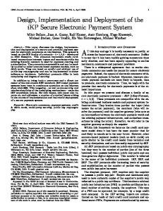
Fig. 1: Component graph for the DMAMAC protocol implementation Component software architecture. The architecture component graph for the DMAMAC nesC implementation is shown in Fig. 1. A module is indicated by a box with a single line, and boxes with a double line specifies configuration of a component. The box with a dashed line denotes a generic module. The grey ovals are interfaces being provided. Generic modules of components similar to Timers can be instantiated multiple times as per application requirement. We rely on several existing components provided by TinyOS 2.1.2 and re-use the MAC Layer Architecture 6 services including Frame Configuration and Slotter Control in the implementation of the DMAMAC protocol. These services are provided by the GenericSlotterC component and are part of the TinyOS distribution (contributions). Interfaces. The DMAMAC component (Fig. 1) uses several components via their provided interfaces to implement the functions as per the protocol specification. We re-use most of the components rather than implementing new ones. The most important components that are used via their provided interfaces are: • • • •
GenericSlotterC providing slotting functionality for TDMA in steady and transient superframes. CC2420ActiveMessageC is the radio component and provides all the radio packets related interfaces. TimeSyncC providing the time synchronisation required to keep all the nodes in the network synchronized. QueueC for packet buffer queues to store incoming and outgoing packets until handled.
The Frame Configuration service from the GenericSlotterC component is used to define the parameters of the transient and steady superframe. The parameters defined include slotsize and superframe length. We use a slotsize of 10 ms, a superframe length of 100 slots for transient mode and 200 slots for steady mode. The Frame Configuration is also used to switch superframes dynamically between steady and transient superframes. For TDMA slot scheduling and control, the SlotterControl service is used. For packet handling we use the CC2420ActiveMessageC interfaces provided by the radio module of the Z1 hardware. The packet sending and receiving interfaces are AMSend and Receive, respectively. The PacketAcknowledgements interface is used for obtaining acknowledgements for transmitted packets and the AMPacket interface is used to for packet data access. The CC2420Packet component provides link data including Received Signal Strength Indicator (RSSI) and Link Quality Indicator (LQI) used for the analysis (see Sect. 4). RadioPowerControl is an interface used to switch the radio on and off. The interfaces provided by the DMAMAC component are: Send, Receive, MacPowerControl, Init and FrameConfiguration. The Send and Receive interfaces are provided for packet handling in both directions: incoming and outgoing. The Init interface is used for initialising the module, after which MacPowerControl is used for switching the component on and off. The FrameConfiguration is provided for modifying the transient and steady superframe length if required by the application. Time Synchronisation. Time synchronisation is a key element of any TDMA-based MAC protocol as all nodes must start on every slot simultaneously. Given the clock drift and varying local time on each nodes, time synchronisation is necessary. We use the Flooding Time Synchronisation Protocol (FTSP) 11 provided with the TinyOS suite to obtain time synchronisation for DMAMAC. A root node is selected (the sink in our case) and the time of the root node is used as global time by the rest of the nodes. The root node sends out a time-synchronisation message at a
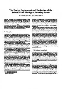
user defined interval and all nodes update their local clock based on the values received from the root node. The TimeSyncC component provides the time synchronisation required and the timing information of each node can be obtained via the TimeSyncInfo interface. Alternatively, we could have used the CC2420TimeSyncMessage component to send time synchronisation information in the notification slot of the sink. But, this would require integrating the time synchronisation implementation into our MAC level implementation. In order to obtain a modular design and demonstrate that DMAMAC can be implemented with a standard time synchronisation component, we directly use the FTSP time synchronisation as a background process. We use a synchronisation rate of 3s, i.e., a time synchronisation message is sent from the root node to all nodes every 3s. Mode-switch implementation. The FrameConfiguration interface is used to implement the mode-switch which can occur in two ways: (1) transient to steady which is a non-critical switch implemented by the sink based on the readings of the sensors and signalled via notification to all the nodes; and (2) steady to transient which is a safety-critical switch decided by the sink based on the alert messages transmitted by one or more sensors. When a node receives a notification message from the sink about change of mode, it uses the FrameConfiguration interface to change the type of superframe used. The loss of a notification packet can affect the mode-switch procedure and thus the process control adversely. This is mainly important for the critical steady-to-transient switch. We therefore implement the notification messages from the sink such that they repeat the current mode in every round. The design of the superframes is such that steady mode superframe is a multiple of the transient mode superframe which means that even in a case where some nodes are not in the same mode (due to notification loss), they can easily synchronise in the next notification message. In addition, the reliability of the protocol can be further enhanced by ensuring that if a node detects that it misses a notification slot, then it switches into transient mode as a safety precaution. In case where the network is still in steady mode, the node will re-synchronise back to steady mode as soon as it correctly receives payload in a notification slot. In the implemented version of the DMAMAC protocol, we Fig. 2: Modified sleep part in the steady included an additional notification slot in the beginning of the sleep superframe parts of transient length (Nt) in the steady superframe as shown in Fig. 2. This is a modification to the original superframe structure 9 to improve robustness and reduced switch delay. 4. Deployment and Experimental Evaluation The Zolertia nodes used for the experiment have a MSP430F2617 low power micro-controller with a 16-bit 16-MHz RISC CPU, 8KB RAM and 92KB of flash memory, and a CC2420 IEEE 802.15.4 complaint transceiver operating at 2.4GHz with a data rate of 250Kbps. The multi-hop network topology used for the experiments is shown in Fig. 3(a). It consists of 3 sensor nodes, 1 actuator node, and a sink node. The senors relay sensor information to the sink and receive notification and data packets (to forward) from the sink. The actuator node only receives data and notification packets. The configuration of the testing application which uses the DMAMAC protocol for communication in the experiments is shown in Fig 3(b). The application mainly uses the DMAMAC protocol to send and receive packets, and also to modify frame configuration (i.e., length of steady and transient) as required. The application uses the generic module TimerMilliC to produce packets at a preset interval. It also initialises (boots) the TimeSyncC component for use by the DMAMAC component. The DMAMAC protocol has been designed for process control application which means that it will typically be deployed in a factory automation setting where there would be numerous machines present creating noise that would effect the operation of the protocol. The noise could be a result of the variation in temperature, vibrations, and electromagnetic noise 12 . To emulate a real process automation environment, we have used an electrical laboratory containing multiple running motors. This allows us to setup a controlled environment in which we can conduct experiments in different scenarios to study the effect of external factors like motor noise on the performance of the protocol.
Fig. 3: Experimental setup: network topology (a) and application structure (b) Our first goal was to validate that the implementation correctly sets the Radio state Current measured radio states. For this, we measured the current to validate the change of Sleep 0.5 mA – 0.6 mA radio states (TX, RX and SLEEP). The values obtained are shown in Tab. 1. TX 21 mA – 22 mA The measurements were made using an oscilloscope with a 3V power source RX 23 mA – 23.5 mA placed with node and a 10 Ω resistor coupled in series. The measured current are in the expected range as per the data sheets for the radio hardware. Table 1: Measured current in Our second goal is to study the impact of noise on packet failures and multiple radio states. how it affects the mode-switch procedure of the protocol. We consider two separate scenarios: a motor room scenario and open room scenario. We measure three metrics: Received Signal Strength Indicator (RSSI), Link Quality Indicator (LQI), and failure of notification packets. We mainly focus on notification packets and parameters measuring its quality because they are directly responsible for the network wide mode-switch. For the open room scenario, we perform two experiments with varying setup, one with line of sight placement and one non-line of sight (or arbitrary placement) of nodes (both with 5 nodes). For the motor room scenario we used the same setup, but with additional running motors. The two scenarios are further discussed below. RSSI values range from -50 dBm to -95 dBm (maximum receiver sensitivity), where values towards -50 dBm are considered to be better. RSSI is the measurement of the power in the received signal and thus gives some indication of pathloss for the signal. LQI values range from 50 to 110 for the CC2420, where values towards 110 are the good ones. LQI is calculated for each packet in TinyOS and indicates link quality based on packet reception. Scenario 1: Motor room. These experiments were conducted in a laboratory with multiple asynchronous induction motors with high wattage (3kW and generating a voltage of 325 V). The idea is to test DMAMAC in an industry-like scenario where motors are running and generating noise including electromagnetic noise. This scenario also includes frequency controllers, and current converters (Direct to Alternating) operating at varying frequencies. During the experiment, we also had students that walked around these motors performing tests. The laboratory in addition includes standard Wi-Fi access points. We considered two placement of the nodes: line of sight placement and (arbitrary) non line of sight placement. The line of sight placement has the nodes placed such that they are visible to each other. The arbitrary placement is around the motors with no direct line of sight. The graphs from the obtained RSSI and LQI measurements from the line of sight placement scenario experiment are shown in Fig. 4(a) and Fig. 4(b). Rounds define the number of notifications received. It can be seen that the link quality and the received signal strength are quite stable. But in a general industrial environmental setup, line of sight placement is not always possible. This is why we also also consider node placement in order to get a more accurate picture of the performance of the hardware. The graphs for the obtained RSSI and LQI measurements from the non line of sight (arbitrary) placement scenario are shown in Fig. 5(a) and Fig. 5(b). Observing these figures, we can see that the link quality is relatively stable, but the RSSI has a large variation through the experiment. Given the collective picture of LQI and RSSI and packet loss, it can be concluded that the arbitrary placement does affect the link quality for the used hardware based on the obstacles and the generated noise. Scenario 2: Open room. The open room scenario uses the same laboratory as the motor room scenario but without any running motors or students around, but Wi-Fi was active in both scenarios. The RSSI values obtained in the open room scenario are shown in 6(a) and the LQI is shown in 6(b). In this scenario, we investigated both line of sight and (arbitrary) non-line of sight placements. The results obtained for both placements are fairly similar and we therefore
Fig. 4: Experimental results for motor room scenario - line of sight placement, RSSI (a) and LQI (b)
Fig. 5: Experimental results for motor room scenario - arbitrary node placement, RSSI (a) and LQI (b)
Fig. 6: Experimental results for the open room scenario, RSSI (a) and LQI (b) only include the line of sight experiment due to space limitations. It can be seen that in comparison with the motor room scenario, the RSSI values are fairly stable over the time, and so are also the the LQI values. The results obtained in both the motor room and the open room scenario show two main things. The notification packet failure is small and is similar across the scenarios and experiments as summarised in Table 2. Thus, the protocol
Table 2: Notification packet failures on nodes 1-3 line of sight (LOS) and non-line of sight (non-LOS). runs across these scenarios with little packet failure. The LQI values show minimum variation in link quality in all experiments. Primarily, we can infer that the environment conditions affect the performance of the protocol, and that the steps taken to make the protocol robust indeed help in these situations. The RSSI measure on the motor room scenario shows large variations which could be an effect of multi-path fading in the non-line of sight scenario. Also, in the line of sight scenario the noise could be a factor. Continuously operating Wi-Fi in the area could also create interference, but has similar effect on both scenarios. However, additional experiments are needed to get definite conclusions on the multi-path effects. 5. Conclusions and Future Work We have demonstrated the practical implementability of the dual-mode DMAMAC protocol for process control. In particular, we have shown how to implement the mode-switch which is a distinct feature of DMAMAC not found in other MAC protocols for process automation. Also, we have shown that DMAMAC can be implemented based on a standard time synchronisation protocol. Our implementation work has also resulted in two improvements to the robustness of the DMAMAC protocol in tolerating packet loss. We have evaluated the DMAMAC implementation in a representative process control automation environment which included sources of noise that interfered with the radio communication and hence affect the protocol operation. These results demonstrated the capability of the DMAMAC protocol to operate in a satisfactory manner in the presence of packet failures, in particular that the critical steady to transient mode-switch was performed properly. The result presented in this paper combined with our earlier work 9 on design and simulation-based evaluation of DMAMAC can be seen as the final step in the development of DMAMAC. A natural extension of the present work would be a large-scale deployment testing of the protocol in order to investigate scalability. Investigating the use of DMAMAC in less safety-critical contexts such as home automation is also a possible direction of future work. References 1. I. F. Akyildiz, I. H. Kasimoglu, Wireless Sensor and Actor Networks: Research challenges, Ad Hoc Networks 2 (4) (2004) 351–367. 2. A. A. Kumar S., K. Øvsthus, L. M. Kristensen, Towards a dual-mode adaptive {MAC} protocol (dma-mac) for feedback-based networked control systems, Vol. 34, 2014, pp. 505–510, the 9th International Conference on Future Networks and Communications (FNC’14)/The 11th International Conference on Mobile Systems and Pervasive Computing (MobiSPC’14)/Affiliated Workshops. 3. P. Suriyachai, J. Brown, U. Roedig, Time-critical data delivery in Wireless Sensor Networks, in: DCOSS, Vol. 6131, 2010, pp. 216–229. 4. P. Suriyachai, U. Roedig, A. Scott, Implementation of a MAC protocol for QoS support in Wireless Sensor Networks, in: IEEE International Conference on Pervasive Computing and Communications, 2009, pp. 1–6. 5. J.-H. Hauer, TKN15. 4: An IEEE 802.15. 4 MAC implementation for TinyOS, Tech. rep., Technical University Berlin (2009). 6. K. Klues, G. Hackmann, O. Chipara, C. Lu, A component-based architecture for power-efficient media access control in wireless sensor networks, in: Proceedings of the 5th International Conference on Embedded Networked Sensor Systems, SenSys 07, 2007, pp. 59–72. 7. Z1 datasheet, zolertia, http://www.zolertia.io//, accessed: 25-01-2016. 8. P. Levis, S. Madden, J. Polastre, R. Szewczyk, K. Whitehouse, A. Woo, D. Gay, J. Hill, M. Welsh, E. Brewer, D. Culler, Tinyos: An operating system for sensor networks, in: W. Weber, J. Rabaey, E. Aarts (Eds.), Ambient Intelligence, Springer, 2005, pp. 115–148. 9. A. A. Kumar Somappa, L. M. Kristensen, K. Ovsthus, Simulation-based evaluation of DMAMAC: A dual-mode adaptive MAC protocol for process control, in: SIMUTools, 2015, pp. 218–227. 10. D. Gay, P. Levis, R. von Behren, M. Welsh, E. Brewer, D. Culler, The nesc language: A holistic approach to networked embedded systems, in: Proceedings of the Conference on Programming Language Design and Implementation, PLDI ’03, 2003, pp. 1–11. 11. M. Mar´oti, B. Kusy, G. Simon, A. L´edeczi, The flooding time synchronization protocol, in: Proceedings of the 2nd International Conference on Embedded Networked Sensor Systems, SenSys ’04, 2004, pp. 39–49. 12. K. S. Low, W. Win, M. J. Er, Wireless sensor networks for industrial environments, in: International Conference on Computational Intelligence for Modelling, Control and Automation, Vol. 2, 2005, pp. 271–276.