messages enabled the information flow to reach the maximum capacity as given by the max-flow min-cut theorem for network information flow. The basic idea of ...
Implementation and Performance Evaluation of Network Coding for Cooperative Mobile Devices Morten V. Pedersen and Frank H.P. Fitzek and Torben Larsen Aalborg University, Denmark, e-mail: [mvpe|ff|tl]@es.aau.dk
Abstract— In this work a performance evaluation of network coding for cooperative wireless networks is carried out. Implementing network coding on commercially available mobile devices, the performance is presented in terms of throughput, delay and energy consumption. In contrast to purely cellular systems, where the mobile devices are only connected to the base station, in cooperative wireless networks, the mobile device, in addition to the cellular communication, establishes short range links to neighboring mobile devices within its proximity. In prior work it has been shown that the newly formed cooperative cluster, also referred as wireless grid, can offer each participating mobile device a better performance in terms of data rate, delay, robustness, security, and energy consumption in contrast to any stand alone device. To improve the performance within the cooperative cluster even more, network coding seems to be a promising technology as it decreases the number of packets to be interchanged among cooperative mobile devices leading to a decreased packet delay. The energy saved by fewer packet transmissions is confronted with the energy needed to carry out the network coding and related overhead. The findings of this paper show that network coding is always beneficial in terms of throughput and delay for the cooperative cluster.
Cellular link (C)
Cellular link (C)
base station C
SR
Short range link (SR)
C
SR
Cooperation
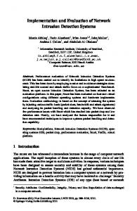
Fig. 1. Cooperative cluster formed by mobile devices using the short range technology in a cellular environment.
messages enabled the information flow to reach the maximum capacity as given by the max-flow min-cut theorem for network information flow. The basic idea of network coding can be illustrated by using the multicast butterfly example in Figure 2.
I. I NTRODUCTION In contrast to purely cellular systems, where the mobile devices are only connected to the base station, in cooperative wireless networks, the mobile device, in addition to the cellular communication, establishes short range links to neighboring mobile devices within its proximity (see Figure 1). In prior work [1], [2] it has been shown that the newly formed cooperative cluster, also referred to as wireless grid, can offer each participating mobile device a better performance in terms of data rate, delay, robustness, security, and energy consumption in contrast to any stand alone device. The improved data rate, delay, and robustness comes obviously by the accumulated cellular links with its inherent diversity. The decreased energy consumption is explained in [3]. In a nutshell, as long as the energy per bit ratio is better in the short range connection than the cellular link, the cooperation will improve the energy consumption. This is for all available and future wireless technologies the case as the path loss is much smaller on the short range communication (around 10 m) than the cellular one (several 100 m). For cooperative wireless networks the network coding seems a viable solution to decrease the traffic within the short range cluster and with that to decrease the delay and the energy consumed. The concept of network coding was firstly introduced for wired networks and presented in [4] where it was shown that allowing nodes in a multicast graph to code incoming
Fig. 2. The butterfly example introduced by Ahlswede et al. in the graph to the right network coding is applied at the bottleneck node 3.
In this example all edges have a capacity of one bit per unit time. By the max-flow min-cut theorem we see that the max-flow from the source s to the sinks t1 and t2 equals two. Thus that the maximum number of bits simultaneously delivered at each of the sinks should equal two. Clearly by inspection of the graph this cannot be achieved without some form of coding, as the middle node is limited to one outgoing bit per time unit. However, by allowing node 3 in this case, to code the incoming bits, we can achieve the max-flow as shown in Figure 2. The butterfly example has later been shown also
for a wireless environment in [5]. Network coding can be a viable solution to decrease the number of packet transmission needed within the cooperative cluster if any relaying is needed or losses occur. In Figure 3 there are some motivating examples, where three mobile devices are connected to the cellular network and all mobile devices are supposed to receive the same two packets a and b.
B
C
A
B
p1
p1
a,
a A
p2
C
p2
b
B
b
a,b
A
Cooperation and Network Coding
Cooperation II
Cooperation I
a,
b
No Cooperation
C
A
B
C
t1
t2
t3
t4
Fig. 3. Non cooperative and cooperative approaches for data download and distribution.
No Cooperation: If the mobile devices are either not willing or able to cooperate, each mobile device needs to receive two packets over the cellular link. As the data rate is low on the cellular link, the transmission will take a certain time and energy. Cooperation I: In case the three mobile devices cooperate, two mobile devices will receive one packet over the cellular link and forward that to the cooperating entities in the cluster. In case packet a and b can be transmitted parallel, the total transmission time is smaller than in the previous scenario. Cooperation II: In contrast to the previous scenario, two mobile devices of the cooperative cluster can not communication with each other directly and need the intermediate device to relay their packets. The intermediate device will happily do so as it will get the two packets that the device is also interested in without using the slower and more energy consuming cellular connection. Thus, the outer devices will forward their packets to the intermediate device, which will forward both to devices A and C. Cooperation and Network Coding: In the last scenario network coding is employed. As before, the outer mobile devices convey their packets to the intermediate device. Now, the two packets are coded by XORing them as given in [6]. The resulting coded packet will be broadcast and received by both outer devices at the same time. Doing so has reduced the number of needed packets to be exchanged from four to three. By this simple example the decrease in the delay is visible. Energy will be saved on the wireless transmission, but the
network coding needs to be taken into consideration. In general we assume N of mobile devices that are within the cooperative cluster. Each mobile device receives disjoint packets from the cellular network that they will broadcast to the cooperative cluster via the short range wireless link for later combining. By doing so, N cooperating mobile devices are N times faster in downloading the packets than a stand alone mobile device. In case the link to some of the mobile devices is error prone, the broadcast has to be repeated. This makes the local exchange less efficient in terms of delay and energy consumption. With network coding the number of retransmission can be significantly decreased. This is achieved sending coded packets that are able to repair one or more packets. For some given scenarios the use of network coding seems promising as it reduces the number of needed transmissions within the cluster. On the other hand the mobile devices may be forced to received more packets and spend additional energy due to the increased complexity introduced by the network coding itself. To have a fair comparison we will look into the energy consumption of the sending, receiving, idle and coding states in Section II. II. F UNDAMENTALS FOR E NERGY S AVING USING N ETWORK C ODING The important parameters that decide whether cooperation and network coding will be successful are the energy consumption of different technologies and the achievable data rates. Therefore in the following those parameters for the cellular network, for IEEE802.11b/g, and the pure coding are given. The energy was measured with the Nokia Energy Profiler on Nokia N95 mobile devices. A. Cellular Network In the cellular environment we conveyed UDP traffic from a server via the 2G/3G network to the mobile phone. At the mobile phone the packet loss rate, data rate, and energy was measured. A summary of the results gathered are presented in Table I. TABLE I P OWER L EVELS U SED I N C ELLULAR - 100 BYTE state receiving idle
power value [W] 1, 314 0, 661
data rate [Mbps] 0, 193 −
loss rate [%] 13, 43 −
B. IEEE802.11b/g Network In the WLAN measurements one sending node was broadcasting multiple packets to ten receiving N95s placed at certain distance between 3 m and 30 m. Different packet sizes were used between 100 byte and 1250 byte. A selection of those values is presented in Table II, where we used the following definitions: data rate: The data rate is calculated by sending 5000 packets per test, multiply it with the packet size and divide it by the mean time needed to run one test.
time: The time we measure referres to a single test sending 5000 packets. There is a pause time of 10 seconds between two tests. packet loss: The packet loss is calculated by all non successfully received packets divided by the overall send packets. energy: The energy is calculated by the power levels in the different states (sending/receiving/idle) multiplied by the time of a given state. We distinguish three power levels of WLAN, namely sending, receiving, and idle. In the idle phase a mobile device is actual listening to the channel but not receiving any packet and the reader should not be confused with the sleep phase where nearly no energy is consumed. The idle phase is measured between two tests. In the sending and receiving phase the mobile device is not all the time active due to the medium access control protocol. So the values presented here are a mean value. TABLE II P OWER L EVELS U SED I N B ROADCAST - 1000 BYTE state sending receiving @ 3m receiving @ 30m idle @ 3m idle @ 30m
power value [W] 1, 629 1, 375 1, 213 0, 979 0, 952
data rate [Mbps] 5, 623 5, 379 5, 115 − −
loss rate [%] − 3, 328 8, 324 − −
Each mobile phone creates a measurement report as given in Figure 4.
The code power application can be configured to perform a number of byte-wise XOR operations in a optimized loop. TABLE III P OWER AND E NERGY L EVELS U SED F OR N ETWORK C ODING ON THE M OBILE P HONE state coding coding idle
power value [W] 0, 593 0, 593 0, 041
energy value [J] 4, 789 0, 191 · 10−6 −
number of operations 25000000 1 −
By these results as shown in Table III we see that the network coding itself has nearly no impact on the overall energy consumption compared to the wireless part. III. C AUTIOUS V IEW ON N ETWORK C ODING Energy consumption in mobile devices is becoming dramatically important for the mobile manufactures, as the mobile device itself is increasingly more energy demanding while at the same time the customer asks for longer stand by times for the devices. As described previously in this paper, the use of network coding can decrease the number of needed transmissions within the cooperative cluster. Obviously this is beneficial for all delay sensitive services. On the other side we need to answer whether network coding will have any positive or negative impact on the overall energy consumption. A. The simple Wheel Example To start with, we look at the wheel example by [6] and extend it with the perspective of energy consumption. N nodes are placed on a circle around one additional node, as shown in Figure 5.
Fig. 4. Single measurement report of receiver for broadcast traffic at 21 m with 1000 byte packet length. The reported values are evaluated offline and contain a plot for the application layer data rate, the power, the elapsed time, and the packet loss for each test (small round circles) and the mean value (solid line). The power plot is different as it carries two values, namely that for the idle and the receiving or sending mode.
C. Network Coding In order to estimate the overall energy consumption of the network coding, an estimate of the energy contribution coming from the actual coding operations need to be found. To find these values an application called code power was developed.
Fig. 5. The wheel topology, where N codes communicate through a relay node placed in the center.
A pair of nodes is located diametrically opposed on the circle and is trying to exchange packets — in correspondence with our prior examples we can assume N/2 overlaid cooperative clusters. Packets have all the same size and are transmitted in slots. A slot is a fixed time which only one node can use for transmissions over the channel. We assume an ideal medium access strategy without collision and full knowledge. As the nodes of one communication pair cannot communicate directly with each other, they depend on the node in the middle to perform relaying. The node in the middle is able to receive all
packets by the outer nodes. Assuming three different states a node can have for a given slot, namely sending, receiving, and idle, the energy can be calculated for the different scenarios. For N + 1 nodes in this example, we will have N + 1 states within one slot. For the energy considerations we assume three different cases, namely the pure relaying, the pure network coding, and the network coding in teams. 1) Pure Relaying: Each node is sending its packet to the middle node that will be forwarded to the reception node by the center node. The calculation of sending nodes is quite easy, as each outer node transmits once and the center node repeats those transmissions. Thus, the number of sending slots equals 2N . As each transmitted packets is received only by one node at the time, the number of receiving nodes is equal to those that has been send. In case one out of N outer nodes transmits, the other (N −1) remaining outer nodes are idle and the center one is receiving. On the other hand, if the center node is sending, one out node is receiving, and (N − 1) outer nodes are idle. Thus the total number of idle nodes is given by 2N (N − 1). As always one, and only one, node is transmitting at the time, the number of sending slots determine also the overall delay D until the full exchange of packets is over. The actions are shown in Table IV. D = 2N
(1)
TABLE IV P URE R ELAYING
overall actions
sending 2N
receiving 2N
idle 2N (N − 1)
2) Pure Network Coding: Now we look at pure network coding as introduced in [6]. In this case each transmission by any outer node is overheard by all other outer nodes. As before, the center node will receive all transmissions from the outer ones and the opposite node (that is actual interested in the packet) can still not receive the transmission of its counterpart. Even though this is still the unicast scenario, overhearing of all packets pays off as the middle node will now code all received packets into one single packet and broadcast it to all outer nodes. As the outer nodes have already received (N −1) packets, the coded packet will enable all nodes to retrieve the missing packet. By decoding the packet, they will get their packet. So now the number of sending slots is reduced to (N + 1). For a better understanding, the actions taken by a single outer node, all outer nodes, and the inner node is given in Table V. As given by the table, one outer node will receive (N − 1) packets, thus (N − 1)N received packets by all outer nodes. The inner node will still receive all N packets. This sums up to N 2 receiving slots. The number of idle slots is easy to calculate as each outer node is idle only once, which sums up to N idle slots. Again the delay for a full exchange of packets is given by the number of sending slots, which is N + 1 for pure network coding. D =N +1
(2)
TABLE V P URE N ETWORK C ODING
single outer node all outer nodes inner node overall actions
sending 1 N 1 N +1
receiving N −1 N (N − 1) N N2
idle 1 N 0 N
Introducing network coding results in a decreased delay, but the number of receiving slots is increased at the same time. Furthermore the number of idle slots is reduced significantly. As the power for receiving is larger than the power for being idle, this may have an impact on the energy consumption. Comparing the pure relaying scenario with the pure network coding, obviously the energy can be reduced by network coding. This is due to the large energy consumption in the idle state for WLAN. Even though there is a sleeping state, where nearly no energy is consumed, the WLAN chipset on the mobile devices seem not to be switching to that state. When we assume a technology that is able to completely turn off the RF/BB when not needed, the results for energy consumption look totally different. As the network coding is always on overhearing packets, it will consume a lot of more energy than the pure relaying approach, where most of the nodes are idle and do not use any energy. Nevertheless, in the next scenario we try to reduce the energy consumption for network coding. 3) Network Coding in Teams: Now pairs of nodes belong to teams. The number of teams within the wheel scenario is given by T . When one team is active, the others are idle, data is exchanged within the active team as in the pure network coding example. The node in the middle still needs to receive all nodes’ transmissions, but will code different packets for each team and therefore will end up in sending more packets. Such an approach would have N + T slots for sending and N 2 /T slots for receiving. The number of idle slots is given by N (N (T − 1)/T + T ). The overall number of slots used for sending, receiving and idle states is given in Table VI. By introducing the idea of teams, the delay will increase compared to the pure network coding. The delay is now given by N +T . D =N +T
(3)
TABLE VI N ETWORK C ODING IN T EAMS
single outer node all outer nodes inner node overall actions
sending 1 N T N +T
receiving N/T − 1 N (N/T − 1) N N 2 /T
idle N (T − 1)/T + T N (N (T − 1)/T + T ) 0 N (N (T − 1)/T + T )
4) Performance Evaluation: If we now look into the performance evaluation for the wheel scenario, we assume the power levels given in Table II. Furthermore we assume 96 nodes on the outer circle, thus 97 nodes in total. In Figure 6 we see that the energy consumption of pure network coding is smaller than pure relaying. But the energy consumption is even more reduced by introducing a small number of teams, the
lowest energy consumption is found when using T = 4. If the number of teams becomes too large, the energy consumption goes up again. But note, having more teams will lead also to an additional delay. Nevertheless the introduction of teams allows a flexible trade off between delay and energy. Now a wireless technology that would use nearly no power in the idle state is assumed such as it is realized in DVB-H. Introducing network coding would use a significant amount of additional energy as given in Figure 7. But also here the usage of teams helps to reduce the energy consumption. By using T = 24, the overall energy consumption will be even smaller than the pure relaying. But note that smaller energy consumption is paid with larger delays.
between idle and receiving/overhearing other packets is small), but the gap could increase for future technologies. IV. N ETWORK C ODING A PPLICATION ON M OBILE D EVICE Now we bring together the bits and pieces and look into the performance of a commercial application for mobile devices using network coding for the communication in the cooperative cluster. A number of mobile devices (in Figure 8 four mobile devices are depicted) within proximity to each other will span the cooperative cluster. All mobile devices are connected in parallel to a cellular operator.
Fig. 8. Cooperative Architecture with Cooperation Server and Cooperation Cluster.
Fig. 6. Energy consumption versus delay for the pure relaying, pure network coding, and network coding in teams for power values of WLAN type.
Fig. 7. Energy consumption versus delay for the pure relaying, pure network coding, and network coding in teams for power values of ideal WLAN type (Pidle = 0).
In a nutshell: The overhearing of packets, the basic principle of network coding, is not for free. In WLAN type communication systems the penalty is very low (the energy difference
Within the core network we implement our own Cooperation Server. All mobile devices will connect to this server to get access to any service. Mobile devices will also report a scan of the wireless neighborhood looking for cooperative partners. As soon as the cooperation server detects the possibility for cooperation (mobile devices are in range and seek the same service), it will inform the mobile devices. For those being in the same cooperative cluster and interested in the same services, the cooperative cluster will retrieve the requested service from a given Internet server and prepare it for cooperative use. A very simple example would be to just take an audio stream and split the audio packets into several streams. The cooperation server could also be used for transcoding of multimedia services. As given in [7] the use of multiple description coding is beneficial for the cooperative cluster in terms of robustness. Such functionality is not implemented yet. The cooperation server is also the optimal place to develop the seeding strategies, a technique to place coded packets into the cooperative cluster in a smart way. In Figure 9 the architecture of the mobile application is given. It shows how different application data flows can be handled. Successfully retrieved packets are stored at the flow cache for potential decoding. The peer info contains the information about what other mobile devices might have for packets to assure the best possible coding. In the output queue are those packets that need to be send to other mobile devices. Those packets are the coding candidates. At a very first test we used cooperation among mobile devices that are in range of each other, thus no network coding
V. C ONCLUSION
"""
!
"""
!!
## ##
Fig. 9. Architecture of the Network Coding application on the mobile phone.
In this work the combination of cooperative wireless networks and network coding is advocated. The combination of those two approaches is beneficial for the throughput, delay and the energy consumption. Besides analytical analysis, we have implemented the network coding and cooperative wireless networking on commercially available mobile devices. First a solid measurement campaign for different wireless communication technologies and the network coding itself was presented. Later a cautious view on network coding was presented. Network coding within a cooperative cluster is always beneficial, but the network coding across multiple cooperative clusters need to be done with care. We have introduced the idea of forming network coding teams offering a trade off between delay and energy. The final performance analysis shows that the idle power of the WLAN technology has a huge impact on potential energy savings - an effect that decreases with a larger number of cooperating devices. Future work will focus on strategies for the cooperation server and the network coding on the mobile device. VI. ACKNOWLEDGMENT
was needed. As given in Figure 10(a), two mobile devices are exchanging the cellular received data (red blocks) over the short range (green blocks). Compared to the non cooperative case, three mobile devices would use a third of the time to download the information and used 17% less energy (using 100 byte packets). Note, for the energy consumption there is space for improvement, which we did not exploit so far (different packets size on the short range, using special WLAN driver options to reduce the energy in the idle mode).
(a)
(b)
Fig. 10. Screenshot of the NetCode application using pure cooperation without network coding (a) and cooperation with network coding (b).
In a second test two mobile devices were placed apart from each other and the third one in between them. Thus the middle one can perform relaying or network coding as given in the last two examples of Figure 3. Figure 10(b) shows the first screenshot with network coding (blue blocks). The number of coded packets (blue blocks) is small due as network coding was firstly tested. But this will change in the final application. Nevertheless, we have shown the applicability of network coding on commercially available mobile devices.
We would like to thank Nokia for providing technical support as well as mobile phones to carry out the measurement campaign. Special thanks to Mika Kuulusa, Gerard Bosch, Harri Pennanen, Nina Tammelin, and Per Moeller from Nokia. This work was partially financed by the X3MP project granted by Danish Ministry of Science, Technology and Innovation. R EFERENCES [1] F.H.P. Fitzek and M. Katz, Eds., Cognitive Wireless Networks: Concepts, Methodologies and Visions Inspiring the Age of Enlightenment of Wireless Communications, ISBN 978-1-4020-5978-0. Springer, 2007. [2] F.H.P. Fitzek and F. Reichert, Eds., Mobile Phone Programming and its Application to Wireless Networking, Number 10.1007/978-1-4020-5969-8 in ISBN 978-1-4020-5968-1. Springer, 2007. [3] F.H.P. Fitzek, P. Kyritsi, and M. Katz, Cooperation in Wireless Networks – Power Consumption and Spectrum Usage Paradigms in Cooperative Wireless Networks, chapter Chapter11, pp. 365–386, Springer, 2006. [4] R. Ahlswede, Ning Cai, S. Y. R. Li, and R. W. Yeung, “Network information flow,” IEEE Transactions on Information Theory, vol. 46, no. 4, pp. 1204–1216, 2000. [5] D. S. Lun, T. Ho, N. Ratnakar, M. Mdard, and R. Koetter, Cooperation in Wireless Networks: Principles and Applications, vol. 1, chapter Network Coding in Wireless Networks, pp. 127–161, Springer, 2006. [6] S. Katti, H. Rahul, W. Hu, D. Katabi, M. Medard, and J. Crowcroft, “Xors in the air: practical wireless network coding,” in Proceedings of the 2006 conference on Applications, technologies, architectures, and protocols for computer communications (SIGCOMM ’06). 2006, pp. 243–254, ACM Press. [7] P. Seeling, F.H.P. Fitzek, and M. Reisslein, Eds., Video Traces For Network Performance Evaluation – A Comprehensive Overview and Guide on Video Traces and Their Utilization in Networking Research, Signals & Communication. Springer, Dec. 2006.