Head motion during PET scanning is widely regarded as a source of image degradation .... terms (Tx, T,, and T,) and rotational terms (Ox, O,, 0,) defining. Operational Spec $ ..... amount of anatomical information for these methods to succeed.
IEEE TRANSACTIONS ON NUCLEAR SCIENCE, VOL. 46, NO. 6, DECEMBER 1999
2059
Implementation and Performance of an Optical Motion Tracking System for High Resolution Brain PET Imaging B.J. Lopresti’, A. RUSSO”~, W.F. Jones3, Member, T. Fisher4, D.G. Crouch4, D.E. Altenburger’, and D.W. Townsend’, Senior Member ‘PET Facility, Univ. of Pittsburgh Dept. of Radiology, B-938 PUH, 200 Lothrop St., Pittsburgh, PA 15213 ’Ecole Polytechnique Federale de Lausanne (EPFL), Lausanne, Switzerland 3CTI PET Systems, Inc., 810 Innovation Drive, Knoxville, TN 37297 4Northern Digital, Inc., 403 Albert Street, Waterloo, ON, Canada N2L 3V2
Abstract Head motion during PET scanning is widely regarded as a source of image degradation and resolution loss. Recent improvements in the spatial resolution of state-of-the-art tomographs may be compromised by patient motion during scanning, as these high resolution data will be increasingly susceptible to smaller movements of the head. We have developed an opto-electronic motion tracking system based on commercially-available technology that is capable of very accurate real-time measurements of the position and orientation of the patient’s head. These positions are transformed to the reference frame of the PET scanner, and could potentially be used to provide motion correction of listmode emission data on an event-by-event basis.
I. INTRODUCTION Recent developments in PET scanner technology have enabled the development of commercial multi-ring tomographs with a theoretical image spatial resolution approaching 2 mm FWHM. Many neuropsychiatric and neurodegenerative~diseases affect small brain structures which are difficult, at current tomograph resolution, to distinguish from adjacent structures of considerably different functional significance. For this reason, it I S advantageous to study the brain using functional imaging techniques with the best achievable resolution. Previously, it has been demonstrated that head movement during PET imaging is a significant source of image degradation and resolution loss [1,2], the exact nature of which depends on the type, magnitude, and frequency of the movements. As the resolution of the scanner increases, small movements of the patient’s head will become significant sources of image degradation and resolution loss. The impact of patient movement on PET functional image data depends mainly on the type of the movement, when the movement occurs, and in what manner the data are analyzed. Movements may occur between serial PET scans (mterscan) or within the acquisition of a scan or frame (Intrascan), and can generally be classified as either random or non-random. Random movements are typically of small amplitude, high frequency, and of random direction. These movements form a distribution around a mean value for each degree of freedom over a given sampling interval, and in general result in a spatially homogeneous loss of effective image resolution. Non-random movements occur less frequently than . random movements, and are typically larger in amplitude and have a preferred direction. These gross movements often result in a sudden shift in the mean value of any or all six degrees of freedom. Potential sources for this type of artifact
could be a sneeze, cough, sudden awakening, response to pain, or adjustment of the lower torso or legs to relieve muscle fatigue. These artifacts would likely produce spatially and temporally variant gradients in image contrast resulting from inaccurate attenuation correction, as the emission scan and the transmission scan would be misaligned. As the transmission scan is typically collected at the beginning of a PET imaging session, these artifacts could potentially become more severe as the imaging session progresses. A third classification is required to describe a common component of patient motion that is characterized by slow, drifting movements of low amplitude and low frequency, which can take up to several minutes to complete. These slow drifts can be observed in any or all degrees-of-freedom, and can be of either random or non-random direction. They are often observed following large, non-random movements, and are typically recoiling motions in the opposite direction. This component of motion should not present a serious obstacle for motion correction, provided the motion detection system is adequately accurate and has a sufficiently high duty cycle to sample them thoroughly. Generally, the effective spatial resolution of an image Aeff depends on both the spatial resolution of the tomograph (reconstructed image resolution) and the magnitude of the movement of the subject during the acquisition of the image given by:
where Ales is the practical spatial resolution of the tomograph (FWHM) and Amov the FWHM of the distribution of the position of the patient’s head around a mean position over the scanning interval [ 11. Methods to correct for patient movement have largely been directed towards the correction of interscan movements. Such methods have generally been image based (software), and involve the spatial registration of serial scans or frames using a mathematical algorithm [3,4]. Other methods utilize an external device, such as a tracking system, to supply information regarding the position of the patient’s head during the scanning procedure. One such device monitors the patient’s head with a pair of CCD TV cameras and triggers the acquisition of a new frame when a movement, is detected beyond a set threshold [5,6]. These frames can then be spatially registered and summed back into a single frame for analysis. A more advanced motion tracking system has been developed based on opto-electronic position sensitive detectors, similar to the POLARIS [7]. This system,
0018-9499/99$10.00
0 1999 IEEE
2060
however, is not commercially available and is not easily adaptable for our desired application. These existing methods, however, are not optimal for correcting high-resolution PET data for movement as the accuracies of these methods are approximately equivalent to the spatial resolution of the tomographs. To recover a maximum of resolution lost to movement it is desirable to use a motion correction method substantially more accurate than the tomograph resolution. Clearly, a method capable of providing highly accurate, high-frequency measurements of the position and orientation of the patient’s head would permit either retrospective or real-time reprojection of lines-ofresponse (LORs)[S]. Such a system would represent an obvious advantage over existing motion correction methods as it would not only address the problem of interscan movement, but also that of intrascan movement. To realize this goal, we sought an inexpensive commercially-available motion tracking system that could be practically implemented in the environment of the PET scanner and would perform satisfactorily. Based on pre-established design and performance constraints, we identified the POLARIS system (Northern Digital, Inc., Waterloo, Canada) to best fit the design criteria. Using this system, we developed and tested an algorithm capable of making highly accurate measurements of the position and orientation of the patient’s head transformed to the reference frame of the scanner. Such information can then be incorporated into a list-mode data stream to provide a means for correcting for patient motion on an LOR basis either in real-time or retrospectively.
11. METHODS A. Design Specijkatons The following design specifications were established for the development of a motion tracking system which would be effective in providing a means for event-by-event motion correction of emission data for a hypothetical PET tomograph with a spatial resolution of 2.5mm FWHM:
General SpeciJications
0
0 0
Ability to simultaneously measure six degrees of freedom Translational accuracy : < 0.5 mm FWHM Rotational accuracy: < 0.3 degrees Sampling frequency: > 1 Hz Real-time acquisition to allow real-time data processing Stability: a stable, time-independent mode of operation must be quickly achieved, after which the performance of the system remains constant. Interference: The performance characteristics of the motion tracking system must not be compromised by the tomograph. Conversely, the motion tracking system will not interfere with the collection of PET data (i.e., obstruction of the PET field-of-view (FOV)). cost: < us$20,000 System must be easily interfaced with PET scanner electronics.
Operational Spec $cations 0
The working volume of the motion tracking system must cover the axial and transaxial scanner FOV.
The overall dimensions of the motion tracking system must be as small as possible, and must be easily mountable in a stable position. The system must not restrict access to the patient nor interfere with the execution of the scanning protocol. The system must be minimally invasive to the patient. The system must be easy to setup and operate.
B. Layout of the System The motion tracking system described in this work was designed, implemented, and tested with an ECAT EXACT HR+ PET scanner (CTI PET Systems, Knoxville, TN) and is based on the passive-mode of the POLARIS motion tracking system (Northern Digital, Inc., Waterloo, Canada), which became commercially-available in 1998. The POLARIS system consists of two main components: The tool interface unit and the position sensor. The position sensor has a compact, lightweight design and is comprised of a stroboscopic infrared flood source and two high-speed digital cameras that operate in the near infrared. Using complex pattern recognition and triangulation techniques the position sensor is capable of simultaneously tracking the position and orientation of up to three targets in its working volume in either active or passive mode. A target can be any object to which at least three infrared-emitting diodes (active mode) or retroreflective disks or spheres (passive mode) can be affixed in a precisely known geometry. The POLARIS system, when pre-programmed with a description of the target(s) of interest, is capable of recognizing the target and computing its position and orientation in space as long as the target remains in the working volume of the position sensor. Active targets can be tracked at a sampling rate of 60 Hz while for a passive target this rate is reduced to 20 Hz. The tool interface unit controls the strobing of the infrared-emitting diodes when the system is operating in active mode, and is not required when the system is operated in passive mode. As the exclusion of the tool interface unit significantly reduces the cost of the POLARIS system and eliminates the need for cables to be attached to the target, we chose to develop this application using the passive mode of operation. This was accomplished without a substantial sacrifice in accuracy or sampling frequency.
1B Front View
50cm
50cm
50cm
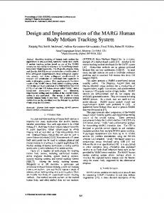
Figure 1: The POLARIS working volume
The POLARIS computes the coordinate transformation between a target and the coordinate system of the position sensor. The coordinate transformation includes translational terms (Tx, T,, and T,) and rotational terms (Ox, O,, 0,) defining
2061
the orientation of the target. The orientation information is output in units of quaternions, which are complex numbers that represent the orientation of an object in space. A quaternion Q consists of both a scalar and a vector, and is represented as:
Q = qo + iq, + jq,
+ kq,
Side Viwr
Neuro-insert
(2)
which can easily be converted to Euler angles (See Appendix)
PI.
The working distance (minimal distance between the target and the position sensor) of the POLARIS was critical to engineer a practical mounting for the device on the PET scanner gantry. This constraint required a modification of the POLARIS position sensor by the manufacturer that would reduce this distance from 140 cm to 85 cm. This modification also reduced the working volume of the POLARIS system, resulting in a hemisphere-cylinder field with a diameter of 50 cm (Figure 1). The mounting for the POLARIS position sensor was designed to provide a rigid and stable support such that the working volume of the position sensor optimally covered the scanner FOV without requiring any permanent modification of the scanner gantry. The upper panel of the mounting consists of an aluminum plate (142 cm x 61 cm x 0.96 cm) reinforced with two 1” square aluminum struts that span the length of the upper side of the mounting plate in order to minimize its flexion. The mounting plate is clamped to the top of the scanner gantry, with vibration dampening achieved by the insertion of a 318” thick sheet of neoprene rubber between the gantry and the mounting plate. The position sensor is mounted in the proper position using two camera brackets that are suspended from the mounting plate. The camera brackets permit the adjustment of both the vertical and angular position of the position sensor (Figure 2). Position sensor
/
\
Camera Bracket
,
’ !
,
Mounting plate
Retroreflective markers (5)
~tr&;rh~;iv€
\
Figure 3. Mobile (left) and reference (right) targets without slippage, and is the least susceptible to the false detection of head movements resulting from movement of the facial muscles (Figure 4). The second target, the reference target, is attached to the inside surface of the neuro-insert (CTI PET Systems, Inc.), which is an annular lead shield that bolts into the ECAT HR+ gantry and limits out-of-field radiation. The neuro-insert was chosen because it provides a convenient surface for the mounting of the reference target within the working volume of the POLARIS and requires no modification of the gantry components. The reference target remains stationary at all times, and its position is precisely known relative to an arbitrary point within the scanner gantry that defines the scanner reference frame. The reference target is comprised of five retroreflective markers, with one of the five markers designated as the origin of the local coordinate system. By making very precise measurments using detailed plans and a precision machine stage, the position of the origin marker can be related to an arbitrary point on the scanner gantry which defines the origin of the scanner reference frame. Because the POLARIS expresses the position and orientation
J Neuro-insert
Figure 2: Layout of the tracking system For this particular application, two tracking targets were used (Figure 3). The first target, the mobile target, is a small (8 cm x 8 cm) lightweight (25 g) matte black plastic plate to which four retroreflective markers are‘ affixed, with their relative positions precisely determined using a digital imaging and metrology system. The mobile target contacts the crown of the head and can be held in place using four elastic bands, which are cinched tightly through holes drilled in the thermoplastic mask. A dense, high-friction foam glued to the contact side of the mobile target contours to the head and provides excellent contact. This method of attachment allows the target to move freely with the head over a wide range
Elastic‘Strap
H&d Holder
Figure 4. Attachment of mobile target to thermoplastic mask
2062
of tracking targets relative to its own reference frame, the POLARIS reference frame, the use of one of the targets as a reference easily allows the expression of the position and orientation of other targets relative to the desired reference using a series of simple geometrical transformations. An added advantage of this arrangement is that the tracking information is insensitive to the placement of the position sensor, as long as a clear line of sight between the position sensor and the reference target is maintained.
C. Coordinate Transformations The series of mathematical coordinate transformations which expresses the movements of the mobile target in the scanner reference frame consist of homogeneous matrices and include terms for position and orientation. The coordinate transformation C is then expressed as a unique matrix resulting from the multiplication of a translational matrix T and a rotational matrix R using unit quaternions such that C = T R [9] (see appendix). The POLARIS simultaneously monitors the position of both ,the mobile target and the reference target relative to the POLARIS reference frame, the transformation of the position of the mobile target in the reference frame of the reference target is easily obtained as:
c,,
Cmwr = cp+.* = (cr-p)-l* cm-p = ( Tr+,* Rr-,,J1* T&, R,, 8
(3)
where C,,-r and C, are the coordinate transformations from the POLARIS to the reference target and the mobile target to the POLARIS, respectively. If the position of the reference target is known relative to an arbitrary scanner reference frame, a simple transformation applied to Cm+will yield measurements of the position and orientation of the mobile target in the scanner reference frame. The series of mathematical coordinate transformations are given below.
D.PerformanceTesting In order to evaluate the performance of the POLARIS in our particular application in terms of accuracy and stability, we performed a series of practical tests. To establish the accuracy of the system, we employed a precise programmable robotic motion stage (accuracy > 10 pm) to move the mobile target through a series of 100 precisely known positions within the scanner FOV. The accuracy of the system was assessed by a 3D linear regression analysis that minimized x2 between the series of known positions and the positions measured by the POLARIS. The test of stability is useful in determining to what level the performance characteristics of the system are guaranteed in a controlled environment. Stability was tested by making -13,000 measurements of the position of a static target in the scanner FOV at 21°C with the same level of ambient light that would be present during an actual scanning procedure.
The transformation from the mobile target to the POLARIS is given by:
The transformation from the mobile target to the reference target can therefore be obtained by substituting equations (4) and ( 5 ) into equation (3).
2063
E. Human Subject Monitoring Following the successful completion of the performance tests, the motion tracking system was employed in a situation which accurately simulated a PET imaging session. Two normal volunteer subjects underwent a simulated PET imaging procedure that lasted for a duration of 60 min, using the standard thermoplastic mask as a head restraint. A third subject was placed in the scanner and instructed to perform a series of tasks to determine whether or not they could generate non-random motion artifacts. The tasks included speaking, coughing, the crossing and uncrossing of the subject’s legs, and a control condition where the subject was asked to lie as motionless as possible for a period of 60 sec. The motion tracking system collected and processed tracking data at a rate of approximately 4Hz throughout both experiments, a rate which could be improved by employing a more powerful computer.
III. msurrs A . Performance Testing The POLARIS system performed exceptionally well in our application, despite the use of the reference target and the coordinate transformations needed to express the position of the mobile target relative to an arbitrary reference point in the scanner gantry. The results of the accuracy test are shown below in table I . The performance characteristics of the POLARIS were also found to be very stable in our typical application environment. In any of five trials of the stability test, the maximum standard deviation around a mean position observed for any translational and rotational DOF of a static target were 0.02 1mm and 0.1 1 degrees respectively. Given these results, it is evident that the system provides stable and accurate measurements with errors well within our imposed design constraints. Table 1, Tracking system accuracy
Error (max)
I 0.28 mm
0.05 mm
I 0.12 mm I 0.280 mm
In general, the motion tracking system was well tolerated by normal human subjects undergoing simulated PET scanning, and provided useful information regarding the nature of head movement in this type of subject population. In order to compare our results to a previously published study of patient motion using normal subjects undergoing simulated PET scanning [l], we summed the 60 min of tracking data into 5 min bins for each DOF (-1100 measurementshin). The mean position and the FWHM of the distribution of measurements around that mean position were computed for each bin of each DOF (Figure 5 ) , and a histogram was generated over a single time bin for a single DOF (Figure 6). The FWHM of the distribution of values for each DOF for both subjects summed over 60 min are presented in Table 2. We also found that non-random motion artifacts could be easily generated from the subject speaking, coughing, or crossing hidher legs. Plots of these non-random motion artifacts are shown in figure 7 for all six DOF.
t x(mm) y(mm) z(mm) 8, (deg) 8, (deg) 8, (deg)
2.242 1.882 1.520 0.762 0.423 0.774
ition FWH I Subject 2 4.4 13 3.363 3.332 1.744 2.243 2.217
IV. DISCUSSION
The POLARIS motion tracking system described in this paper meets all of the established design criteria that identify a commercially-available system that is suitable to be implemented into a motion correction algorithm for the eventby-event reprojection of list-mode acquired emission data. In our application environment, the POLARIS demonstrated exceptional performance in terms of accuracy and stability. It has the added advantage of being able to track multiple targets in its working volume simultaneously, which allows the tracking data to be easily transformed to the reference frame of any target the POLARIS is able to identify. The position measurements of the targets are updated at a frequency of up to 20Hz (50 ms / measurement), which should provide satisfactory temporal resolution for the integration of the tracking measurements with the list-mode acquired emission data. Furthermore, the POLARIS system requires no lengthy setup or calibration procedure and can be removed and reinstalled with ease, as the tracking data are insensitive to the location of the position sensor in space. The performance of the POLARIS system was not compromised by ambient light and it can be operated reliably in a fully illuminated room, as the system operates in the near infrared. Reflections of any sort do not confound the tracking performance of the POLARIS as they are typically not intense enough or of the proper shape to be mistakenly identified as a valid retroreflective marker. Even if such reflections were of sufficient intensity and shape, it is highly unlikely that these reflections would assume a recognizable target geometry. The POLARIS ignores all retroreflective markers that do not fit a preprogrammed target description. A series of tests using various light sources and intensities were unsuccessful at compromising the tracking accuracy of the POLARIS system, and all tests described in this paper were conducted in a fully illuminated room. The POLARIS system demonstrated that it is well suited for use with human subjects undergoing PET scanning. The means of affixing the mobile target to the thermoplastic mask resulted in no discomfort and allowed the mobile target to move freely with the subject’s movements over a wide range. Using the POLARIS system, we were able to demonstrate that motion artifacts can be a serious source of image degradation and resolution loss, especially for a tomograph with spatial resolution approaching 2 mm. As a typical PET brain imaging session can last up to several hours, it is unreasonable to expect a patient to remain motionless for this length of time. A common head restraint, the thermoplastic mask, restricts the range of possible head movements but does not eliminate them to a degree sufficient for a tomograph with 2
2064
mm resolution [l]. Though other types of head restraints are conceivable, the most effective methods for restraining the patient’s head are generally the most invasive. Clearly, a method to correct for motion artifacts is a much needed development for the hllest potential of high-resolution PET to be realized. It has been shown previously that in normal human subjects undergoing simulated PET scanning the cumulative distribution FWHM around a mean position for each movement degree-of-freedom increased with increasing study length, both with and without head restraint [l]. This study also indicated that the movement FWHM values were comparable regardless of study length when the position data records were divided into independent 5-min intervals. The increase in cumulative movement FWHM can be explained in one of two ways: the distribution FWHM around a stable mean position is increasing (increase in random movements), or the mean position is shifting with the distribution FWHM around that mean position remaining more or less constant (increase in non-random movements). The POLARIS, due to its high measurement frequency, allows approximately 1,100 independent measurements of the absolute position and orientation of the patient’s head over a 5 rnin period (-4Hz). Figure 5 indicates that both the mean position and the FWHM of the distribution around it vary with time, with the FWHM values generally increasing with increased study length when the data are binned into independent 5-min intervals. However, this increase in FWHM does not necessarily indicate an increase in the amplitude and frequency of random movements. A histogram plot of all of the absolute values of the x translational degreeof-freedom over the 50-55 min interval in a representative subject are shown in figure 6 . These data show four distinctly separate distributions, each with a different mean position. It is also evident that the FWHM values for these individual
increase in the frequency andlor amplitude of non-random movements within these individual 5-min segments is mainly responsible for the time-dependent increase in the distribution FWHM. In this example, the distribution FWHM around an apparent mean position is 2.48 mm. It is clear that this value is influenced by the spread in the mean positions of the four individual distributions, and not the FWHM of each individual distribution. As the FWHM of each of these component distributions is substantially smaller (-0.5 mm FWHM) than the value obtained by considering them as a whole, the problem of movement in high-resolution PET imaging would seem to be sufficiently addressed if one were to correct for or eliminate this component of patient movement.
I
12
-21 -20
-19 -18
-17
-16 -15
Xabs (mm)
Figure 6. The distribution of all -1,100 values of the x DOF over the 50-55 rnin time bin, showing four separate mean positions over that 5 min interval
Correction of non-random movement artifacts is not a straightforward task, especially if the movement occurs within the acquisition of a scan or frame. Typically, image registration techniques are applied to serial PET scans to correct for interframe non-random movements. It is not
-X
Translational DOF
0
20
40
Time (min)
Time (min)
Time (min)
Time (min)
0
60
20
40
60
Time (min)
Rotational DOF
0
20
40
60
Time (min)
Figure 5 . Mean position and FWHM of distribution of movements around the mean position for a representative subject undergoing simulated
PET scanning for all six degrees of freedom, binned into 5 min intervals (-1,100 measurements/ 5 min).
2065
Translational DOF
E E
2
2 7
1.5 1.
1
m
----
_,---
* , _ .