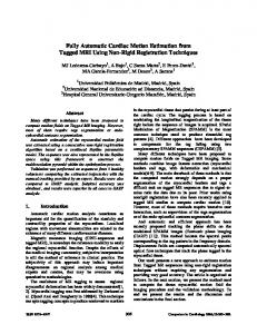
Optical tracking systems that employ markers, such as the. Vicon system, are able ..... of 1126 hand tracking trials, each of which lasted for 5 seconds and were ...
Fully Automatic Optical Motion Tracking using an Inverse Kinematics Approach Jonathan Maycock1 , Tobias R¨ohlig1 , Matthias Schr¨oder2 , Mario Botsch2 and Helge Ritter1 Abstract— Optical motion tracking systems often require a lot of manual work to generate clean labeled trajectories. This can be a deterrent if the goal is the creation of large motion tracking datasets. Especially in the case of hand tracking, issues of occlusion (often self-occlusion by other fingers) make the post-processing task very difficult and time intensive. We introduce a fully automatic optical motion tracking method that utilizes a model based inverse kinematics approach. The Hungarian method is used to efficiently calculate associations between model markers and motion capture markers and we demonstrate an elegant solution to the problem of occlusions using a posture interpolation step.
I. I NTRODUCTION Optical tracking systems that employ markers, such as the Vicon system, are able to capture highly accurate kinematic movement data, but a serious drawback of these systems is the need to post-process the data in order to arrive at fully labeled trajectories. Especially in the case of hand tracking, occlusions of one or more markers, which can occur especially when grasping and manipulating objects, can mean many hours of manually intensive work to clean the data [1]. Another difficulty is the presence of ghost markers, caused by unwanted reflections, that if categorized incorrectly can lead to large errors in the tracking process. We propose a novel fully automated tracking technique for marker based optical tracking systems. At its heart it relies on using articulated models in an inverse kinematic mode to ensure only realistic postures are arrived at. Associations between model nodes and 3D points delivered by the optical system are efficiently computed using an adapted version of the Hungarian method [2]. Ghost markers that do not lead to realistic postures, checked using inverse kinematics (IK), are ignored. Reappearing plausible markers are used as the end points of a posture interpolation step to ensure smooth trajectories. Our algorithm operates in an online mode and in an offline mode that uses knowledge of the full trajectory to solve issues of occlusion [see Sect.III-C]. Although our examples are focused on hand tracking in this paper, the method itself is general. Once models are available for the objects in the scene, our method is fully automatic and makes the rapid generation of large datasets of motion interactions possible. This has positive 1 J. Maycock, T. R¨ ohlig and H. Ritter are with the Neuroinformatics Group in the Faculty of Technology, Bielefeld University, Germany jmaycock/troehlig/helge at
techfak.uni-bielefeld.de 2 M. Schr¨ oder and Mario Botsch are with the Computer Graphics & Geometry Processing group in the Faculty of Technology, Bielefeld University, Germany maschroe/botsch at
techfak.uni-bielefeld.de
Fig. 1. Snapshot of the method tracking two hands (each with 26 DoF) and a number of rigid body objects synchronously. The small blue spheres on the objects are model effectors and the multi-colored spheres are the unlabeled 3D motion capture data points.
implications for the Learning by Demonstration [3], [4] robotic community and indeed many fields in which realistic motion tracking data is required. Figure 1 shows a snapshot of our approach in action with two hands, each with 26 Degrees of Freedom (DoFs), and a number of rigid body objects being tracked. II. R ELATED W ORK In a recent paper, Meyer et al. [5] proposed a method using least square optimization to allow online marker labeling of human trajectories in a fully automatic manner. Our approach distinguishes itself from theirs in a number of ways. The main difference is that we use IK to articulate the models in the scene. This allows us to sparsely cover the people or objects we are tracking. Especially in the case of human motion tracking this allows for more natural movements to be made. It also allows us to handle occlusions in a way that is not possible with their approach [see Sect.III-C]. Finally, unlike in their paper in which only single skeleton tracking is demonstrated, our approach is a general one and allows for multiple objects to be tracked in parallel. Schubert et al. [6] extended the approach to allow arbitrary poses be used in the initialization phase. Aristidou and Lasenby [7] also achieved online automatic tracking and put an emphasis on predicting the position of missing markers using an unscented Kalman filter. Their method also used IK, but only to maintain bone length.
Indeed a major drawback of their approach is that they do not use physically plausible models to restrict model movements to realistic configurations. Furthermore, without a knowledge of the underlying model they require markers to be placed on every segment, which is not a requirement of our method. Hornung and Kobbelt [8] also employed IK, but required groups of markers to be placed on each segment as the underlying structure of tracked bodies had to be learned. Other approaches such as Cerveri et al. [9] and Klous and Klous [10] only work in an offline mode and strive to achieve very accurate compensation for the movement of the skin with relation to the underlying skeleton. Such accuracy, while nice to have, is not required for many applications and furthermore the complexity of the used models make realtime application impossible to achieve. Hand tracking and especially hand posture estimation is a difficult problem due to the complexity of the hand itself, which has, excluding position and orientation, up to 27 degrees of freedom [11], [1]. This has resulted in many researchers turning to data-gloves [12], [13] or coloredgloves [14], [15] to track hands. Wearing gloves, especially those embedded with sensors, can impede natural movements and even the most accurate are outperformed by optical tracking systems [16]. Some recent systems track bare hands [17], [18], [19], [20], but even though these methods have improved considerably using depth based sensors, they still cannot rival the accuracy of marker based optical tracking systems [1]. There are at least two commercial systems designed to reduce the burden of manual labeling: Vicon’s Blade [21] and Motion Analysis’ Cortex [22]. However, both these systems rely on well labeled data with only small gaps in trajectories as input and therefore an element of manual post-processing is still required. Furthermore, they do not use an inverse kinematic approach and it is therefore suggested that each segment has at least one attached marker. III. AUTOMATIC T RACKING M ETHOD The method relies on fitting models to the 3D unlabeled point data provided by a motion tracking system. The problem reduces to finding the articulation of the loaded models that minimizes the overall distance error to the 3D point data. A. Initialization Figure 2 shows the initization steps in our algorithm. To avoid alignment of models to motion data points issues, ghost markers should be minimized and all valid markers should be visible in the first frame of a capture session. In the Automatic Clustering step the Euclidean cluster algorithm in the Point Cloud Library (PCL) [23] is used to automatically cluster spatially close motion data points in the scene. For cases in which on average the distance separating objects is larger than the size of the objects in the scene this performs well. However, a manual correction may need to be applied if the scene does not meet this specification. This configuration can be saved and later loaded to ensure subsequent trials are automated.
Fig. 2.
Overview of the initialization procedure.
In the Load Models step the assumption is that a database (DB) of two types of models exists: rigid body models and complex multiple DoF models. For our system simple rigid body models such as a cube, sphere, cylinder etc., which can be scaled and have fixed motion capture marker positions, were defined and stored in the DB. We also use the hand model introduced by Schr¨oder et al. [18], but stress once again that the method itself is a general one that scales to different complex models. It is also possible to “on the fly” create rigid models by simply selecting a set of markers that are attached to a rigid object and saving the configuration (the positions of all markers in the model relative to the first marker). In order to ensure that the method can optimally fit complex models to raw Vicon data a calibration posture is adapted. For full human tracking this could be the T-Pose, and for the hand tracking we adopt a pose in which the hand is placed flat on the table with the fingers slightly spread and the thumb extended away from the fingers towards its joint limit. Ensuring a good match between the placement of markers on the hand and effectors on the model is aided by photographing the hand on a sheet of grid paper. In general it is important to accurately position object markers such that they conform to the position of effector points on their associated models, and thus facilitate correspondences to be made. The loaded models s ∈ S are then aligned to the target clusters t ∈ T by trying all possible combinations (s 7→ t) in a brute-force manner and selecting the assignment with the lowest cost. A model is denoted as a cluster of source points s = (s1 , . . . , sk )T and a target cluster of motion capture points t = (t1 , . . . , tl )T . In the Alignment and Scaling step Principal Component Analysis (PCA) is used to calculate the transformation matrices Ts and Tt , which describe the position and orientation of each s and t in canonical form, respectively. This allows us to compute the transformation matrix Tts needed to initially align each model s to each
optimal associations between clusters s and t (Optimize Assignment step). This we achieve by in each frame employing the Hungarian method [2], [24] which minimizes the cost min m(i,j)
Fig. 3. Inverse kinematics based tracking. The details of the highlighted Gap Handling step are shown in Fig. 4.
cluster of motion capture points t: Tts = Tt T−1 s .
(1)
The PCA eigenvectors used to construct Ts and Tt are determined up to sign only. We therefore try all possible combinations of eigenvector orientations (by multiplying them by ±1) for the construction of the mapping Tts , and select the one resulting in the smallest geometric distance. Note that for good PCA alignment it is important that marker configurations are not isotropic. We also use the PCA results to calculate oriented bounding boxes for each cluster and model. The difference is used to calculate a scaling factor that stretches or contracts models to fit the observed data. In the case of hand tracking this is necessary as a wide variety of human hand sizes exist. The PCA step is followed by a rigid Iterative Closest Point (ICP) step to correct for slight errors of the initial alignment. In the Optimize Pose step we solve the problem of optimally assigning model points to target points using the Hungarian method (see next section III-B). This is followed by an IK step to allow the model’s pose to be updated to better match the target points (also section III-B). The best matching model is found using sbest = arg min [E(t, s) + αD(t, s)] ,
(2)
s∈S
where S is the set of loaded models and the function D calculates the difference in the number of markers between the t and s. E returns the mean euclidean distance between t and s and α is a weighting factor that can be tuned depending on how noisy the initial scene is (i.e., missing markers or erroneous ghost makers). For our tests α was set to 1 as the setup was optimised to ensure clean data at least in the initial frames. This matching mechanism compares each model to each cluster, respectively. B. Tracking using inverse kinematics Figure 3 shows the steps involved in our tracking approach. Every marker based optical motion system suffers from disappearing valid markers and appearing ghost markers and it was therefore important to be able to compute
k X k X
m(i, j) ksi − tj k ,
(3)
i=1 j=1
where m(i, j) = 1 if si is matched to tj , otherwise it is 0. This ensures that each model marker is matched to a unique target marker. The Hungarian method requires as input a square k × k distance matrix, but due to either ghost markers or missing markers it can happen that the number of points in the clusters s and t differ. We handle this by padding the distance matrix with extremely large values [25]. The time complexity of the Hungarian method is O(k 3 ), which is very efficient considering the relatively small number of markers that are tracked in most motion capture setups. If a source marker disappears (Marker Missing step) the gap filling procedure is invoked (see Section III-C). Otherwise, the Inverse Kinematic step presented by Schr¨oder et al. [18] is used to minimize the distance error between all s = (s1 , . . . , sk )T and t = (t1 , . . . , tk )T cluster pairs with equal numbers of markers (now sorted w.r.t. the above marker assignment). The IK problem, t = s(θ), can be solved by iteratively finding a parameter update ∆θ from the previous frame θ that minimizes the following function: 1 1 ks(θ + ∆θ) − tk2 + kD∆θk2 . (4) 2 2 The first term models the least squares error between the effectors si and their target positions ti . The second term regularizes the under-determined problem by damping the parameter update ∆θ with a diagonal matrix D of damping weights. We minimize (4) using a Gauss-Newton approach and in each iteration the following linear system is solved � JT J + D δθ = JT (t − s), (5) E (∆θ) =
where J is the Jacobian matrix of the effector positions � � ∂s ∂si J= = . (6) ∂θ ∂θj i,j The calculation of J is described in [26] and solving the system (5) yields the update direction δθ. The process is iterated until the Gauss-Newton minimization converges, which typically requires 5–10 iterations. As a starting value for ∆θ we use the final update from the previous frame. In order to help prevent unrealistic or indeed physically impossible model configurations we employ joint limit avoidance [27], [18] in the final Update Models step. C. Gap handling Figure 4 displays how our method handles occlusions which result in gaps in marker trajectories. The first step is to freeze the joints of the model affected by the missing marker (Freeze Affected Joint(s)). The motion capture frames are then played forward until a marker reappears (Find Next Possible Marker) in close proximity to the model. The
Fig. 5. A virtual finger is shown as it moves through space and is bent. In the second rendering the motion capture marker is no longer visible. Once the marker reappears, inverse kinematics are computed in order to verify that the posture is possible and then the intervening frames in which the marker was missing can be updated using interpolation of the affected joints.
Fig. 4. Overview of how gaps in the raw data provided by the motion capture system are handled.
only exception to this is when the marker belongs to an intermediate segment (e.g., in the case of the hand perhaps there is a marker on one of the proximal phalanges) along the kinematic chain. In this case a visible marker at the end of the kinematic chain (in our example at a distal phalange) can drive the entire chain to realistic postures. Otherwise the affected joints are held fixed until a new marker appears. Once this happens the model is articulated towards this marker using an Inverse Kinematic and Update Model step. As long as the Euclidean distance error is below a threshold (calculated as the average error from 3D motion capture points to effector points on the model plus a small term) the marker is accepted (Distance Threshold Exceeded step). In many cases of appearing ghost markers, this ensures that the model is not pulled into erroneous configurations. However, we note that if a ghost marker appears in a kinematically valid position, this will actuate the model in a way that does not reflect the real motion. If a marker is visible in frame t, disappears for n frames, and re-appears in frame t + n + 1, we determine the missing joint angle values θt+1 , . . . , θt+n for all involved joints by smoothly interpolating the states between time t and t + n + 1 (Smoothly Interpolate Joint Angles step). A simple linear interpolation of the boundary values θt and θt+n+1 would ˙ lead to discontinuities in the angular velocity θ(t). We avoid this and additionally minimize unnecessary oscillations by finding a joint angle function θ(t) that interpolates the C 1 boundary constraints θ and θ˙ at times t and t + n + 1 while minimizing angular acceleration: Z t+n+1 � �2 ¨ min θ(t) dt. θ(t)
t
Because of the uniform time steps of the tracking system we can safely discretize temporal derivatives by recursive finite differences, such that finding the missing n joint angle values
leads to a simple n × n linear system to be solved. If more than one marker is simultaneously missing then the algorithm fills all gaps in a parallel fashion. Figure 5 shows an example in which a marker disappears while the affected finger is changing its position and posture simultaneously. In this example the steps in which the joints are frozen up to the decision that the reappearing marker is valid are omitted and only the resulting smooth trajectory is shown. Small differences between the model dimensions and the real hand and slight errors from the motion capture system combine to make it not always possible for the model effectors to exactly reach the 3D motion capture positions. We note that larger gaps can result in important articulation information being lost. For example when the finger bends and straightens again while a marker at its end is occluded. IV. Q UANTITATIVE E VALUATION To test the effectiveness of our approach we used a dataset of 1126 hand tracking trials, each of which lasted for 5 seconds and were captured at 200 FPS. They include motion tracking data from 18 subjects who performed grasping motions with a range of objects with various sizes and shapes that could be grasped with a single hand. All subjects had 26 markers attached to their right hands and were tracked using 14 Vicon cameras in the Manual Intelligence Lab [28]. The task was to grasp individual objects and place them in a bowl and then return the hand to its starting position. Vicon Nexus [29] was used to manually label the trials to facilitate a comparison with our automatic technique. The raw unlabeled marker data contained both ghost markers and gaps. Figure 6 shows the difference between the average joint angles of the hand model in the manually labeled and automatically labeled conditions across all frames for each trial. Note that the difference for each trial is calculated by first subtracting all manually labeled joint angles over all frames from all automatically labeled joint angles over all frames. The absolute value of the resulting matrix is then normalized by the number of frames and joint angles, which results in the positive scalar values shown in the
Fig. 6. The average difference in degrees between 1126 manually labeled trials and the same trials processed using our automatic approach. The ROI contains trials that had a higher than average number of mislabled markers in the manual labeling case and therefore resulted in larger differences between both methods. The average angle trajectory for the highlighted red trial can be seen in Fig. 7.
graph. The mean angle difference across all trials is 0.085 degrees with a standard deviation of 0.12. We stress that the distribution and order of the trials chosen is not relevant and the criteria for choosing these particular trials was that they were correctly labeled up to the end grasp posture. In the ROI the relatively high differences can be explained by the fact that some of these trials include parts of the experiment after the end grasp when the reliability of the manually labeled data deteriorates. Due to the extremely long time needed to manually label the trials, labelers were told to concentrate on labeling up to the end grasp and the final part of the trial in which the hand returned to the starting position could be ignored. This meant that in some cases mis-labellings by the Nexus software were not corrected if they occurred after this point. Figure 7 is a clear example in which this occurs. Up to ROI-1 there is a perfect match (e.g, not only do the average angles over frames align, but importantly the actual absolute difference in joint angles over the frames is 0 or very close to 0) between our method and the manually labeled case. However in ROI-1 the outputs differ and a less smooth average angle trajectory is visible in the manually labeled trial. A look at the data revealed this was indeed caused by incorrect labeling. It is interesting to note that even though the averaged joint angles align in ROI-2, the postures are different. The averaged absolute value of the
difference of both sets of joint angles over the frames in this part of the trajectory was approximately 3 degree (see the plotted red line in Fig 7). To ensure that we do not penalise our method by including the end of the trials which contain poorly labeled data, we only match the first 500 frames of the trials. V. D ISCUSSION The development of this technique has effectively consigned the tedious and time consuming task of manually labeling motion capture datasets to the past. Work that before could take weeks or months can now be realized in a matter of hours. It opens up the possibility of capturing much larger quantities of human motions that can be used in a variety of scenarios. For example, until now many robotic researchers have had to turn to large simulated datasets such as GraspIt! [30] to generate realistic hand postures on robot platforms. While such resources are to be commended, it is our belief that if real human motion is not used as input to these datasets, important aspects of our evolved skill set will remain unaccounted for. Within our research group it means that we can quicken the pace towards endowing our anthropomorphic robot hands with real human-like capabilities. The gap handling (see Sect. III-C) procedure only works in offline mode. In online mode our current approach is to simply hold the affected joints frozen until a good candidate
Fig. 7. Average joint angle at each frame in both the manually labeled and automatically labeled conditions for an exemplar trial (the highlighted trial in Fig. 6). Also shown (in red) is the average joint angle difference per frame between both methods.
marker reappears at which point IK are employed. We argue that our approach not only reduces the time needed to process motion capture data, but is potentially more accurate too. As we use a model based IK approach, the tracked articulated objects are restricted to realistic postures. This is in contrast to some well known gap filling techniques such as spline fill, which computes an interpolated spline in Euclidean space R3 , or pattern fill, which simply mimics the movement of a selected neighbour marker. In benchmark runs the online version of our method achieved 75 FPS while tracking a single hand with 26 markers. Increasing the number of objects in the scene to two hands (each with 13 markers) and three rigid objects (with a total of 9 markers) the method slowed to 35 FPS. However, if we turn off animation of the complex and detailed hand model (which is done on the CPU) the FPS throughput of the algorithm doubles. To improve performance further we are investigating a GPU implementation. In future work we will apply machine learning to the task of predicting the position of occluded markers with data from markers only seen by a single camera utilized to narrow the search space. Also planned is the integration of physics based models to add realistic collision detection and further ensure, along with the existing joint limit avoidance contraints, that unnatural configurations of models do not occur. VI. ACKNOWLEDGMENT This work was supported by Cluster of Excellence Cognitive Interaction Technology (EXC 277) funded by the German Research Foundation (DFG). Our thanks to Benedikt Ellinger for his great help generating the data. R EFERENCES [1] N. Wheatland, Y. Wang, H. Song, M. Neff, V. Zordan, and S. J¨org, “State of the art in hand and finger modeling and animation,” in Eurographics State of the Art Report, 2015. [2] H. W. Kuhn, “The Hungarian method for the assignment problem,” Naval Research Logistics Quarterly, vol. 2, no. 1–2, pp. 83–97, 1955. [3] D. C. Halbert, “Programming by example,” PhD Thesis, University of California, Berkeley, USA, 1984. [4] S. Schaal, “Is imitation learning the route to humanoid robots?” Trends in cognitive sciences, vol. 3, no. 6, pp. 233–242, 1999.
[5] J. Meyer, M. Kuderer, J. M¨uller, and W. Burgard, “Online marker labeling for fully automatic skeleton tracking in optical motion capture,” in Int. Conf. on Robotics and Autom. (ICRA), 2014, pp. 5652–5657. [6] T. Schubert, A. Gkogkidis, T. Ball, and W. Burgard, “Automatic initialization for skeleton tracking in optical motion capture,” in Int. Conf. on Robotics and Autom. (ICRA), 2015, pp. 734–739. [7] A. Aristidou and J. Lasenby, “Real-time marker prediction and cor estimation in optical motion capture,” The Visual Computer, vol. 29, pp. 7–26, 2013. [8] A. Hornung and L. Kobbelt, “Robust and automatic optical motion tracking,” in Virtuelle und Erweiterte Realit¨at, Workshop der GIFachgruppe VR/AR, 2004. [9] P. Cerveri, A. Pedotti, and G. Ferrigno, “Kinematical models to reduce the effect of skin artifacts on marker-based human motion estimation,” J Biomech., vol. 38, no. 11, pp. 2228–2236, 2005. [10] M. Klous and S. Klous, “Marker-based reconstruction of the kinematics of a chain of segments: a new method that incorporates joint kinematic constraints,” Journal of Biomechanical Engineering, vol. 132, no. 7, pp. 132–138, 2010. [11] A. M. R. Agur and M. J. Lee, Grant’s Atlas of Anatomy, 10th ed. Lippincott Williams and Wilkins, 1999. [12] M. Fischer, P. van der Smagt, and G. Hirzinger, “Learning techniques in a dataglove based telemanipulation system for the DLR hand,” in Int. Conf. on Robotics and Autom. (ICRA), 1998, pp. 1603–1608. [13] J. Steffen, J. Maycock, and H. Ritter, “Robust dataglove mapping for recording human hand postures,” in Int. Conf. on Intelligent Robotics and Applications (ICIRA), 2011, pp. 34–45. [14] R. Y. Wang and J. Popovi´c, “Real-time hand-tracking with a color glove,” ACM Transactions on Graphics (TOG), vol. 28, no. 3, p. 63, 2009. [15] M. Schr¨oder, C. Elbrechter, J. Maycock, R. Haschke, M. Botsch, and H. Ritter, “Real-time hand tracking with a color glove for the actuation of anthropomorphic robot hands,” in IEEE-RAS Int. Conf. on Humanoids, 2012, pp. 262–269. [16] J. Maycock, J. Steffen, R. Haschke, and H. Ritter, “Robust tracking of human hand postures for robot teaching,” in IEEE/RSJ Int. Conf. on Intel. Robots and Systems (IROS), 2011, pp. 2947–2952. [17] I. Oikonomidis, N. Kyriazis, and A. Argyros, “Full DOF tracking of a hand interacting with an object by modeling occlusions and physical constraints,” in Int. Conf. on Computer Vision (ICCV), 2011, pp. 2088– 2095. [18] M. Schr¨oder, J. Maycock, H. Ritter, and M. Botsch, “Real-time hand tracking using synergistic inverse kinematics,” in Int. Conf. on Robotics and Autom. (ICRA), 2014, pp. 5447–5454. [19] A. Tagliasacchi, M. Schr¨oder, A. Tkach, S. Bouaziz, M. Botsch, and M. Pauly, “Robust articulated-ICP for real-time hand tracking,” Computer Graphics Forum, vol. 34, no. 5, pp. 101–114, 2015. [20] S. Sridhar, F. Mueller, A. Oulasvirta, and C. Theobalt, “Fast and robust hand tracking using detection-guided optimization,” in Proc. of Comp. Vision and Pattern Recognition (CVPR), 2015, pp. 3213–3221. [21] “Blade 3. Vicon Motion Systems Ltd.” [Online]. Available: http://www.vicon.com/products/software/blade [22] “Cortex. Motion Analysis Corp.” [Online]. Available: www.motionanalysis.com/html/industrial/cortex.html [23] R. B. Rusu and S. Cousins, “3D is here: Point cloud library (pcl),” in Robotics and Automation (ICRA), 2011 IEEE International Conference on, 2011, pp. 1–4. [24] J. Edmonds and R. M. Karp, “Theoretical improvements in algorithmic efficiency for network flow problems,” J. ACM, vol. 19, no. 2, pp. 248–264, 1972. [25] C. Elbrechter, M. G¨otting, and R. Haschke, “Image Component Library (ICL),” http://iclcv.org. [26] S. R. Buss, “Introduction to inverse kinematics with Jacobian transpose, pseudoinverse and damped least squares methods,” 2009, unpublished survey. [27] T. F. Chan and R. V. Dubey, “A weighted least-norm solution based scheme for avoiding joint limits for redundant joint manipulators,” IEEE Trans. on Robotics and Autom., vol. 11, pp. 286–292, 1995. [28] J. Maycock, D. Dornbusch, C. Elbrechter, R. Haschke, T. Schack, and H. Ritter, “Approaching manual intelligence,” K¨unstliche Intelligenz – Issue Cognition for Technical Systems, pp. 287–294, 2010. [29] “Vicon Nexus. Vicon Motion Systems Ltd.” [Online]. Available: http://www.vicon.com/products/software/nexus [30] A. T. Miller, “Graspit!: A versatile simulator for robotic grasping,” IEEE Robotics and Automation Magazine, vol. 11, pp. 110–122, 2004.