Implementation Aspects of RF-repeaters in Cellular Networks Panu Lähdekorpi, Tero Isotalo, Sultan Usama Khan, and Jukka Lempiäinen Department of Communications Engineering Tampere University of Technology Tampere, Finland E-mail:
[email protected]
Abstract—This paper discusses essential implementation aspects of simple amplify-and-forward type repeaters from the radio network planning point of view. Different RF-repeater configurations are assessed through numerical analysis and field measurements in WCDMA network. The target of this paper is to show the important factors regarding the repeater deployment, which have significant impact on the overall cellular network efficiency. The paper shows the impact of repeater donor antenna beam width on the repeater deployment flexibility. Moreover, the impact of repeater on the optimum BS antenna tilt angle is presented using two macrocellular topologies. Finally, the significance of repeater placement in the repeater antenna line is emphasized through field measurements using an outdoor-toindoor repeater configuration for WCDMA.
f
d
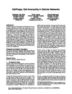
Donor Antenna
I. I NTRODUCTION Since the capacity of the modern mobile communication systems is interference limited, the planning of such networks is focused on minimizing interference while trying to provide the required service with a minimum cost. RF-repeater can be used in interference limited networks to locally boost coverage and capacity. However to keep the interference at minimum, the configuration for the RF-repeater must be carefully selected. Interference related issues will rise especially in case of simple amplify-and-forward repeaters, which are not able to separate between the desired and unwanted signals. The performance of the RF-repeaters has been studied in several publications in the past. In papers [1], [2], [3], the impact of repeaters on coverage and capacity has been studied. Later on, the author in [4] has presented simulation results for improving HSDPA capacity inside buildings, which are served by RF-repeaters. However, the implementation aspects of such repeaters have not been widely discussed from the radio network planning point of view. The target of this paper is to provide practical guidelines for RF-repeater deployment in interference limited wide band code division multiple access (WCDMA) networks. The implementation aspects are discussed by showing numerical calculations and measurement results with different repeater configurations, concerning the donor antenna type, mother base station antenna tilt settings, and the location of repeater in the antenna line. After shortly presenting the structure of repeater implementation in Section II, the paper is divided into three study cases. First, the impact of donor antenna beam width on the deployment flexibility of repeater is shown by describing the
Mother Base Station Outdoor Serving Antenna
Fig. 1.
Indoor DAS
General structure of repeater implementation in cellular network.
scenario and the results in Section III. Section IV explains the impact of repeater on the optimum BS antenna tilt angle by showing the selected configurations and results. In Section V, the method of increasing the repeater performance by changing the location of repeater in the antenna line is presented by showing the measurement scenario and the results. Finally, all the results are concluded in Section VI. II. R EPEATER I MPLEMENTATION In this paper, RF-repeater is considered ideal from the antenna isolation point of view. Therefore, the maximum allowable repeater amplifier gain is not limited by the coupling loss between the two repeater antennas. The general structure of repeater implementation is presented in Fig. 1. The location of the repeater in proportion to the hosting base station in the horizontal direction can be expressed using the distance, d and the horizontal misalignment angle φ. The deviation of φ from the main beam direction (i.e., from φ = 0 in Fig. 1) causes additional loss in the repeater link due to the shape of the horizontal antenna pattern of the hosting base station.
Fig. 2. Observed ∆P using 65◦ antenna. Values from white to black: [20 15 10 5 0] dB.
Fig. 3. Observed ∆P using 33◦ antenna. Values from white to black: [20 15 10 5 0] dB.
However with typical 3-sectored macrocellular base station antennas having half power beam width of 45◦ - 90◦ , the pattern attenuation is small at relatively wide angle in the horizontal direction. Thus from the donor macro cell point of view, the deployment of repeater is widely feasible in the cell area. The antenna line of repeater consists of two parts: servingand donor antenna line. While the donor antenna line connects the repeater unit to the donor antenna of the repeater, the serving antenna line carries the signal to the mobile stations. Different types of serving antenna line implementations exist. If the repeater is to be used for an outdoor traffic hot spot, a single, directed, outdoor macro-/micro cell antenna could be used as the serving antenna. However, if outdoor macro cell is used to transfer the radio signal inside buildings, distributed antenna system (DAS) could be utilized (Fig. 1). The DAS could be used to provide smooth indoor coverage throughout the building. More discussion about using DAS for providing indoor coverage with repeaters can be found e.g. from [5].
channel is equal in all cells. The cell isolation at the donor antenna of the repeater can be expressed as:
III. D ONOR ANTENNA
BEAM WIDTH
The donor link of the RF-repeater has an important role from the system level point of view, since the repeater itself amplifies all signals in the system bandwidth – including intercell interference. MATLAB-based numerical calculations were performed to study the impact of donor antenna beamwidth on the cell isolation provided by repeater. To study the cell isolation, only the link between the repeater and the mother base station was modeled and the observation point was located at the donor antenna of the repeater. The cell isolation can be inspected by observing the difference in the received pilot channel power levels of the two strongest cells, assuming that the received signals from the rest of the surrounding cells are severely attenuated and that the transmit power of the pilot
∆P = RSCP1 − RSCP2 ,
(1)
where RSCP1 and RSCP2 are the received pilot channel power levels of the strongest and the second strongest cells correspondingly. The donor link was analyzed by comparing two different donor antennas at the repeater. The selected horizontal donor antenna beam widths are 65◦ and 33◦ to study the impact of horizontal beam width of the donor antenna on the cell isolation (indicated using ∆P ). The narrower the horizontal beam in the donor antenna, the better is the attenuation of interfering signals from surrounding cells. The target was to find out how much impact the donor antenna horizontal beam width has on the flexibility of the repeater deployment over the cell area. The flexibility was studied by setting a threshold for the minimum ∆P value, and inspecting what is the size of the area in the cell, where the repeater can safely be deployed using the selected threshold. Both donor antennas selected ([6], [7]) are typical panel antennas intended to be used at the base stations of cellular networks. The BS site spacing of a hexagonal topology (so called Cloverleaf topology) was set to 1.2 km and the antenna height of all antennas (including repeater antennas) was set to 25 m. Propagation environment was modeled using flat terrain. The repeater donor link was modeled using the general free space loss (FSL) formula assuming line-of-sight (LOS) conditions for the repeater donor link connections to all base stations in the network. The LOS condition was assumed between the donor antenna and the interfering base stations as well, since all the base station and repeater antennas were installed at the same height throughout the flat ground network. The donor antennas are assumed to be directed exactly towards the hosting base station antenna and the misalignment angle, φ as
presented in Fig. 1, depends on the location of the repeater. The hosting base station was selected based on the strongest received pilot signal level for each studied location. The results are presented in Fig. 2 and 3. Different tones of gray represent a 5 dB step in ∆P . In Fig. 2 and 3, white corresponds to a difference of 20 dB or more (good interference isolation), while the darkest tone of gray corresponds to a difference of 5 dB or less (high interference amplification, poor isolation). From Fig. 2 and 3, the ∆P decreases as the repeater distance increases. This behavior is typical behavior to any cellular radio system due to decreased serving cell dominance, when moving towards the cell edge. However, it is important to notice that with the donor antenna of 33◦ HPBW, the optimum location misalignment angle φ is not 0◦ , but actually around 30◦ measured from the main beam direction of the host BS (see V-shape in the footprint in Fig. 3). The optimum φ = 30◦ occurs, because the next tier BS antenna is always located just behind the main beam direction of a hosting BS and is equipped with identical antenna direction in the ideal Clover-leaf topology. When the donor antenna of the repeater is switched into 65◦ HPBW antenna, the ∆P mostly depends on the repeater distance rather than on the misalignment angle (Fig. 2). This can be explained by the wider donor antenna beam width: the wide donor beam is not able to isolate the other cells even if repeater is significantly misaligned as it was the case with the 33◦ donor antenna. Finally, the area of acceptable ∆P is significantly larger in case of 33◦ donor antenna. According to the results, the acceptable area (i.e., where ∆P > 15 dB) is increased 57% in every cell if the horizontal repeater donor antenna halfpower beamwidth is dropped from 65◦ to 33◦ . However in this numerical calculation example, the repeaters were suffering LOS conditions to the other cells thereby representing a worstcase scenario. Finally it should be noted that ideal hexagonally distributed site locations were used, which is usually not possible to accomplish in practise. Therefore, the level of ∆P can become highly case specific. Field experiment results using different donor antenna setups are discussed in [8]. IV. BASE
STATION ANTENNA TILT
Since the general target of repeater is to serve the users at the cell edge, some space is left for re-optimization of the mother base station antenna configuration. The mother base station antenna tilt was studied together with repeaters to be able to provide general guidelines for antenna tilting in repeater enabled cellular networks. The studies are based on numerical calculations performed over macrocellular WCDMA network, which was modeled using MATLAB. An Okumura-Hata based propagation model was used to describe the mobile radio channel. The numerical, system level, analysis was performed on a flat terrain (no digital map, no shadowing) using [9] as propagation environment framework. The numerical analysis means, that the performance of the network was studied by numerically calculating the observed performance in all locations of the studied area. The donor links of repeaters had LOS conditions to the mother cells.
TABLE I S YSTEM PARAMETERS FOR BS ANTENNA TILT STUDY. Parameter Carrier frequency System bandwidth Repeater distance Repeater serving antenna EDT Area correction factor Building penetration loss Number of repeaters (Clover-leaf topology) Number of repeaters (Triangular topology)
Value 2100 3.84 500 5 −5 15 1 1/2
Unit MHz MHz m ◦
dB dB rep. / cell rep. / cell
Different electronical down tilt (EDT) angles at the base stations were tested with and without repeaters. The tilt angle was varied between 0 and 10 degrees in all base stations in the studied cellular network. Furthermore, the antenna tilt behavior was compared using two different macrocellular topologies: hexagonal (a.k.a. the Clover-leaf topology) and Triangular topology (see [10] for further information about topologies). Fig. 4 shows the two topologies and the repeater locations. The single user performance in the network in each network location can be estimated by observing the received signal-to-interference-and-noise ratio (SINR) of the high speed downlink shared channel (HS-DSCH). According to [11] the instantaneous SINR can be defined as S SIN R = SF · , (2) (1 − α) · Iown + Ioth + N where SF is the spreading factor used in HS-DSCH (SF = 16 for HSDPA), S is the received power on the HS-DSCH, Iown is the interference power from the serving cell, α is the code orthogonality factor (α = 0.5 used), Ioth is the total interference power from the other cells, and N is the noise power of the receiver. The received instantaneous SINR for the HS-DSCH was modeled by assuming constant transmit powers of the base stations. For more information about the SINR modeling details, see [12]. Table I lists the key parameters of the network configuration used in studying the BS antenna tilt. Three-tier network was used in calculating the SINR, but the result samples are taken inside the 2nd tier base stations at the network center to ensure the inclusion of the interference effect (see Fig. 4, gray area). The repeater amplification ratio (i.e. the repeater gain) was increased together with the EDT angle to compensate the varying loss from the vertical pattern of the base station antenna during tilt. Furthermore, serving antennas of the repeaters had fixed tilt. The results of average SINR on HS-DSCH are presented in Fig. 5 as a function of EDT angle. First, the results without repeaters are discussed and then compared to the scenario with different repeater configurations. As shown in Fig. 5, the optimum EDT angle is found at 6◦ EDT (repeaters off) with Clover-leaf and Triangular topologies. This is in line with the earlier studies about antenna tilt (e.g. in [13]) made using the Clover-leaf macrocellular topology. Using EDT angles smaller than the optimum will cause decrease in average SINR due to high inter-cell interference. Furthermore, with EDT angles higher than the optimum, the cell edge coverage
R
R R R
R R
R R
R
R
R
R
R R
R
R
R
R
R
R
R R
Fig. 4.
Mother cell
R
R
Triangular topology
Donor antenna
Repeater configuration for the two network topologies.
Average SINR of HS−DSCH [dB]
14
GR2 Repeater
LDAL3
LDAS
GR3
Mother cell
Fig. 6.
Repeater antenna line configuration for the configurations 1 - 3.
V. R EPEATER ANTENNA LINE
13
12
11
Clover−leaf (1 rep / cell) Triangular (1 rep / 2 cells) Clover−leaf REP OFF Triangular REP OFF
10
9 0
LDAS=10 dB
LDAL2
R
Clover-leaf topology
GR1 Repeater
Conf. 3
R
LDAL1 Mother cell
R
LDAS
Repeater
Conf. 1
R
Repeater antenna line (LRAL=32 dB)
R
Conf. 2
R
1
Fig. 5.
2
3
4 5 6 7 BS antenna tilt angle [°]
8
9
10
Average SINR as a function of EDT angle.
will decrease rapidly with the EDT angle thereby heavily limiting the average SINR. After deploying repeaters, the results in Fig. 5 show, how the optimum EDT angle becomes difficult to define. Instead of EDT being easy to optimize, the SINR becomes more insensitive to the EDT angle, when using repeaters in the network. Interestingly in Clover-leaf topology, the SINR continues to increase hand in hand to the EDT angle. This can be explained by the uniform repeater distribution in the network. Since repeaters are uniformly distributed across the network (Clover-leaf topology, 1 repeater / cell), the lack of cell edge coverage caused by the excess EDT can be fully compensated by the repeaters. However in Triangular topology, the repeaters are located only in the problematic areas and large portion of the network area is left out from the repeater coverage. Hence, repeaters are not able to fully compensate the loss in cell edge coverage at high EDT values as illustrated in the results (Fig. 5, EDT 10◦ , Triangular topology). However with repeaters, Triangular topology, and high EDT, the problematic areas become well covered (increased SINR), which keeps the average SINR constant at EDT angles 6◦ -9◦ as shown in Fig. 5.
As already discussed in many papers (e.g., in [3], [4]) the uplink direction is sensitive to the noise amplified by repeaters. However, the location of the amplifier unit in the repeater antenna line has an impact on the system performance, especially if the antenna line of the repeater becomes long. The effect of differing repeater antenna line setup was studied by measurements in HSDPA enabled WCDMA network. In the measurement setup, WCDMA signal was taken from outdoor macrocellular network and was fed to indoor in order to provide service into a university building. The three studied repeater antenna line configurations for the outdoor-to-indoor configuration are presented in Fig. 6. In Configuration 1, the repeater was located near the donor antenna (donor antenna line loss, LDAL1 = 6 dB). In Configuration 2, the repeater was installed in the middle of the repeater antenna line (LDAL2 = 13 dB). Finally in Configuration 3, the repeater was placed near the serving antenna system (LDAL3 = 22 dB). The components in the repeater antenna line include coaxial feeder cables, 3-way splitter, and jumper cables including connectors. A typical, directive, 17 dBi sector antenna was used as repeater donor antenna (located on roof), while three omnidirectional, 2 dBi indoor antennas were used in indoor. The indoor coverage provided by the repeater was built by implementing a DAS with 10 m antenna spacing. The measurements were performed in office corridor, one floor below the antennas, using a laptop with HSDPA capable data card. All field measurements were done using the same antenna line components, measurements routes, and antenna locations – only the repeater location in the antenna line was changed. As presented in Fig. 6, the total attenuation caused by the lossy components in the repeater antenna line, LRAL , was 32 dB (including e.g. feeder cables, splitters, and connectors) excluding antenna gains and repeater gain. The attenuation from the lossy components in DAS, LDAS , was 10 dB. The noise figure of the repeater was 3 dB. The measurements were performed in empty network (no interference or shared resources from other users). The impact of repeater on received UL interference at the mother base station was measured by increasing the repeater
TABLE II R EPEATER SYSTEM DETAILS IN THE MEASUREMENTS . Conf. 2 68 +8 32 13 −104
Conf. 3 80 +20 32 22 −104
gain in 1 dB steps (no traffic in the network). The target was to find the largest applicable repeater gain to be used for each antenna line configuration. Fig. 7 shows the observed behavior of uplink interference in the three measured repeater configurations. The initial noise floor of an empty cell was measured to be -105 dBm, measured with repeater off. Repeater gain was selected by observing the point, where the UL interference was increased by 1 dB. Increase of 1 dB was selected, since it does not yet cause significant reduction to the macro cell performance. Based on Fig. 7 and using the previous 1 dB rule, repeater gains of GR1 = 60 dB, GR2 = 68 dB, and GR3 = 80 dB were selected for the different antenna line configurations 1 - 3 (see Fig. 6). The details of the selected repeater configurations are gathered in Table II. Fig. 8 shows the cumulative distribution function of the measured throughput samples gathered, when measuring with the three antenna line configurations. As presented in Fig. 8, increase in the repeater gain setting directly provides higher HSDPA throughput. The observation is valid, since the relative repeater antenna line gain increases (although repeater antenna line losses remain constant) thereby causing improved received signal strengths at the receiver. Improved coverage leads into better radio channel conditions and higher allowed throughput experienced by the receiver. The measured, average, throughput was improved from 1896 kbps to 2557 kbps, when changing from Configuration 1 to Configuration 3. At the same time the received signal code power (RSCP) measured from the pilot channel was increased from -97 dBm to -76 dBm thereby indicating clearly improved coverage. Since the increase in the DL throughput was comparable to the corresponding coverage improvement (i.e., the RSCP improvement) between the three configurations, extensive DL repeater noise was not observed during the measurements, although as high repeater gain value as 80 dB was used in Configuration 3. One reason why the downlink is less sensitive than the uplink is in the receiver properties: downlink receiver has insignificant antenna gain and also higher inherent noise figure, when compared with uplink receiver. Furthermore, the use of DAS with omnidirectionally radiating low gain antennas decreases the repeater link gain in downlink and reduces the downlink noise effect. VI. D ISCUSSION
AND
C ONCLUSIONS
It was shown by numerical calculations, how the beam width of the donor antenna of the repeater has an effect on the feasible repeater deployment area. In ideal hexagonal network, 57% increase is observed in the area where repeater
Configuration 1 Configuration 2 Configuration 3
−99 UL interference level [dBm]
Conf. 1 60 Ref. 32 6 −104
−100 −101 GR2
G −102
R1
G
R3
−103 −104 −105 −106 55
Fig. 7.
60
65
70 75 80 Repeater Gain [dB]
85
90
Measured UL interference level for the configurations 1 - 3.
1 0.9
Configuration 1 Configuration 2 Configuration 3
0.8 0.7 0.6 CDF
Parameter Selected GR [dB] Relative repeater ant. line gain [dB] Total rep. ant. line loss, LRAL [dB] Donor ant. line loss, LDAL [dB] Measured UL int. (donor cell) [dBm]
−98
0.5 0.4 0.3 0.2 0.1 0 0
500
1000 1500 2000 2500 3000 HSDPA MAC layer throughput [kbps]
3500
Fig. 8. Measured HSDPA medium access control layer throughput for the repeater antenna line configurations 1 - 3.
provides acceptable cell isolation if the horizontal repeater donor antenna half-power beamwidth is dropped from 65◦ to 33◦ . The behavior of HSDPA SINR as function of electrical down tilt angle of the base station antenna was analyzed using numerical calculations. Based on the results, SINR becomes more insensitive due to repeaters, especially if repeaters are used in every cell (i.e. in Clover-leaf topology). However, already with reduced number of repeaters (i.e., in Triangular topology) the utilization of repeaters made possible to use higher antenna tilt angle at the base stations compared to the original optimum values without reduction in average received SINR. Network wide use of the larger tilt gives indication of stronger isolation between the cells and also stronger received signal levels near the base stations. However, deeper analysis is required to verify this.
The impact of repeater amplifier unit location in the repeater antenna line on the overall repeater performance was studied by measurements. The results showed that the repeater should be located as near as possible to the serving antenna system in order to achieve optimised repeater performance. By installing the repeater near the serving antennas, the antenna line loss in the donor link side can be maximised, which enables the utilization of higher repeater gain without causing increased interference (amplified noise) in the uplink direction. Since the total repeater antenna line loss remains unchanged during the optimisation process, the repeater system can benefit from the increased repeater link gain by means of clearly increased repeater throughput. According to the measurements, an improvement of 35 % was observed in the average throughput due to optimisation of the repeater antenna line. ACKNOWLEDGMENT The authors would like to thank the Department of Communications Engineering, Tampere University of Technology, Finland and the Centre for Wireless Network Design, University of Bedfordshire, UK for providing the funding and premises for the studies made in 2007-2010. R EFERENCES [1] W. Lee, D. Lee, The Impact of Repeaters on CDMA System Performance, in Proc. 51st IEEE Vehicular Technology Conference, Vol. 3, pp. 15–18, 2000. [2] M. Bavafa, H. Xia, Repeaters for CDMA Systems, In Proc. 48th IEEE Vehicular Technology Conference, Vol. 2, pp. 1161–1165, 1998. [3] M. Rahman, P. Ernström, Repeaters for Hotspot Capacity in DS-CDMA Networks, IEEE Trans. Vehicular Technology, issue 3, vol. 53, pp. 626633, May 2004. [4] K. Hiltunen, Using RF repeaters to Improve WCDMA HSDPA Coverage and Capacity Inside Buildings, in Proc. 17th IEEE PIMRC’06, 2006. [5] T. Isotalo, P. Lähdekorpi, J. Lempiäinen, Improving HSDPA Indoor Coverage and Throughput by Repeater and Dedicated Indoor System, EURASIP Journal on Wireless Communications and Networking, 2008. [6] Kathrein product 742215 antenna specification, web site, http://www.kathrein.de [7] Kathrein product 742351 antenna specification, web site, http://www.kathrein.de [8] T. Isotalo, P. Lähdekorpi, J. Lempiäinen, Improving HSDPA Indoor Coverage and Throughput by Repeater and Dedicated Indoor System, EURASIP Journal on Wireless Communications and Networking, April 2009. [9] Network Planning Strategies for WCDMA (NPSW), application note, 2001. [10] J. Itkonen, B. Tuzson, J. Lempiäinen, Assessment of Network Layouts for CDMA Radio Access, EURASIP Journal on Wireless Communications and Networking, 2008. [11] H. Holma, A. Toskala, HSDPA/HSUPA for UMTS, John Wiley & Sons Ltd., 2006. [12] P. Lähdekorpi, J. Itkonen, J. Lempiäinen, Comparison of RF-Repeater Efficiency in Macrocellular Network Topologies, in Proc. 16th European Wireless Conference, 2010. [13] J. Niemelä, T. Isotalo, J. Lempiäinen, Optimum Antenna Downtilt Angles for Macrocellular WCDMA Network, EURASIP Journal on Wireless Communications and Networking, Vol. 5, Issue 5, October 2005.