discuss a combined physical, medium access control (MAC) and network layer ... merely as remote radio heads distributed across the service area. However ... system, the master clock of the base station may be directly phase-locked to the ...
Implementation Concepts for Distributed Cooperative Transmission V. Jungnickel, L. Thiele, M. Schellmann, T. Wirth, A. Forck
W. Zirwas, T. Haustein, E. Schulz
Fraunhofer Institute Telecommunications, Heinrich-Hertz-Institut Einsteinufer 37, D-10587 Berlin, Germany
Nokia Siemens Networks GmbH & Co.KG St. Martinstraße 76, D-81617 Munich, Germany
Abstract—Information theory predicts huge performance gains in terms of spectrum efficiency by using cooperative transmission from multiple base stations. Cooperation eliminates inter-cell interference and it enables a higher channel rank. The isolated cell capacity is an upper bound for unlimited backbone capacity, infinite signal processing power and infinite channel feedback. We discuss a combined physical, medium access control (MAC) and network layer approach targeting minimal implementation loss while relaxing assumptions. It is based on frequency-selective channel quality identifier (CQI) reports to the serving station selecting the right user(s) on a given resource with best signal to interference and noise ratio (SINR). Such scheduling is performed independently in each cell. In adjacent cells it forms a group of users whose mutual interference is smaller than on average. The task of cooperative transmission is to further reduce the mutual interference within this group. In a multi-user system, the group shares only part of the spectrum. Feedback can hence be limited to the granted resource blocks. Based on virtual pilot sequences we reduce the pilot overhead and use a suitable mirror feedback scheme in addition. Altogether the feedback overhead is reduced by 2 orders of magnitude.
I. I NTRODUCTION Cooperative transmission refers to multiple base stations serving jointly a set of users scheduled onto the same resource in their respective cells. Using cooperative signal processing, the interference among the cells is reduced. For this reason, base stations exchange data signals. Channel information is measured at the terminal side from broadcast pilot signals and fed back to the base station. The principal concept has been proposed in [1, 2]. See also a performance analysis in [3] and a recent review article [4]. A measurement-based analysis is provided in [5]. Current cellular systems are interference-limited at least for small inter-site distances between 500 m and 1 km typical for the deployment of the Universal Mobile Telecommunications System (UMTS) in urban areas. In the informationtheoretic limit cooperative transmission could reach the bound of isolated cells [6] if we provide unlimited backbone capacity, infinite signal processing power and infinite channel feedback. The backbone may be realized using optical fibers between the base stations or replacements as microwave and freespace optics. Signal processing power becomes increasingly available at low cost [7]. However, feedback is ultimately bounded. The transmitter power of mobile terminals limits the achievable up-link capacity over cellular distances. Battery power is limited as well. In this paper, we develop a high-level implementation
978-1-4244-2941-7/08/$25.00 ©2008 IEEE
d2
d1
exchange data and CSI over X2
local processing unit
local processing unit x2
x1
B2
B1
channel feedback
H11
Figure 1.
channel feedback
H22 H21
T1
d2
d1
H12
T2
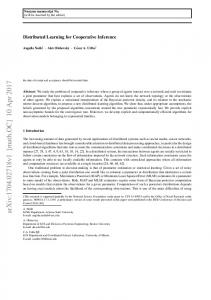
Principle of distributed cooperative transmission.
concept for distributed cooperative transmission. We discuss essential ingredients such as synchronization of base stations, multi-cell channel estimation, efficient feedback of channel state information (CSI) and propose an integrated protocol architecture for the physical, MAC and network layers realizing a distributed cooperative cellular system. The paper is organized as follows. Section II introduces the distributed implementation concept. In Section III, synchronization of the base stations is considered. Section IV describes how to get the CSI efficiently to cooperative base stations. Section V investigates distributed cooperative transmission, the role of the effective channel and the benefit of user-specific pilots. Section VI summarizes the proposed cooperative transmission protocol. II. D ISTRIBUTED I MPLEMENTATION One of the keys to introduce cooperative transmission into modern cellular systems is that the cooperative algorithm can be implemented in a distributed fashion, see [8]. In early work, e.g. [1–5] cooperative beam-forming has been performed at a central unit having all channel knowledge and where all data streams are available. Transmitted signals are jointly precoded and then distributed to the base stations acting merely as remote radio heads distributed across the service area. However, modern cellular networks as the Long Term Evolution (LTE) of the Third Generation Partnership Project (3GPP) have a flat and no traditional hierarchic architecture. Base stations act as autonomous network nodes. There is no central unit where cooperative processing could be done.
1035
Asilomar 2008
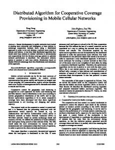
full CSI feedback [1 ms] 20 Mhz, 2x2 MIMO 7 cells, 100 RB 8 pilots/Tx/RB 5 bit quantization for Re(H) and Im(H) feedback = 224 Mbit/s
Figure 2. Options for data flow synchronization at cooperative base stations in the 3GPP LTE/SAE network. Left: Multicast on S1, Right: Unicast on S1, distribution over X2.
Figure 3.
mirror feedback [1 ms] 20 users/cell, each 5 RB 20 Mhz, 2x2 MIMO 8 pilots/Rx/RB 5 bit quantization for Re(H) and Im(H) feedback = 800 kbit/s
Feedback estimation in a simple interference scenario.
There is a straight forward distributed implementation of the cooperative processing, see Fig. 1. Each base station acquires global channel knowledge i.e. about all terminals served by adjacent base stations. The 3GPP LTE network (see Fig.2) is made of a star-like feeder network denoted as S1 and an additional meshed X2 network over which base stations can communicate with each other. The CSI can be exchanged over this X2 interface between cooperative base stations and the cooperative signal processing can be performed redundantly in each cooperative node. Next the data are provided synchronously at the interface to the physical layers in each base station. Each cooperative node applies only the locally relevant beam-forming weights to the streams and forms the locally transmitted signal in this way. Such a distributed implementation is fully equivalent to central processing, i.e. the desired signal d1 in Fig. 1 is maximized at the terminal T1 and the interference due to co-channel transmission of d2 to T2 is suppressed at the location of T1.
problem is to insert time stamps in the data packets already at the aGW. Next one replicates the MAC controller in each cooperative base station and synchronizes all replicas with the original controller in the serving base station using an X2 protocol based on time stamps. A second approach is shown in Fig. 2, right. Data packets are sent as unicast from the aGW over S1 to the serving eNB, where the unique MAC controller for this user is situated. There is an additional X2 data path between the eNBs, over which ready-to-send data can be copied with controlled timing from the master to the slave eNB also involved in the cooperative transmission. Copied data are accompanied by implicit or explicit mapping information on which resources they are transmitted. In this way, data to be transmitted at a slave eNB can be provided synchronously with the transmission at the serving eNB. This approach may be simpler in terms of hardware effort and implementation.
III. S YNCHRONIZATION
Cooperative beam-forming requires the estimation of large numbers of channel coefficients from the serving and interfering base stations to each terminal. For a first estimate of the feedback overhead, consider a simple interference scenario in Fig. 3. A way how to estimate the channel for multiple cells is described in the next subsection. With 7 cells, 2 transmit antennas each, 100 resource blocks (20 MHz bandwidth in 3GPP LTE), 8 pilots per antenna in each resource block and 10 bit quantization for the channel coefficients one would arrive at an unthinkable feedback rate of 224 Mbit/s with an update interval of 1 ms. In the following we describe a way how this rate can be reduced by more than 2 orders of magnitude without significant loss of relevant CSI.
For distributed cooperative transmission, we need better synchronization than in current cellular networks. At first, base stations act coherently, like in a single-frequency network. Hence, the carrier frequency in the radio front-ends and the overall symbol and frame clocks must be synchronized for all base stations. This can be realized using the global positioning system (GPS). GPS-locked Rubidium reference clocks can achieve an accuracy below 10−11 relative to the center frequency. The frame start can be synchronized with a mean and maximum jitter of 10 and 30 ns, respectively, using the common one-pulse-per-second (1PPS) signal. This is more than sufficient for cooperative transmission. In a commercial system, the master clock of the base station may be directly phase-locked to the GPS to reduce costs [9]. For indoor base stations, the GPS can be replaced by network synchronization using the IEEE 1588v2 protocol. It is based on a GPS-locked grandmaster and slave units at each base station [10], [11]. Synchronization of the data flow is required in the distributed approach. Basically there are two options. In the first approach (Fig.2, left) the stream of a user is multi-cast from the advanced gateway (aGW) over the S1 feeder network to the cooperative base stations. In this way, a particular data packet may arrive asynchronously over the network at each base station, denoted as enhanced nodeB (eNB), since the routing delays can be different. A potential solution for this
IV. C HANNEL STATE INFORMATION AT THE BASE STATION
A. Virtual Pilots The virtual pilot concept in Fig. 4 reduces the pilot overhead at the cost of mobility [12]. Pilots in sectors are assumed orthogonal. Each site is identified by one sequence out of an orthogonal set. Common pilots are scrambled over time by this site-specific sequence. One simply takes all pilots in a slot and multiplies them with a given chip from the sequence. There is a particular sequence assignment to base stations, see Fig. 4. The idea is based on partial cross-correlation. For some sequences families with length L, e.g. Hadamard or DFT, there are subsets of sequences being mutually orthogonal already for window lengths being an integer fraction of L. In general, we
1036
cell plan for sequences
down-link
performance 10 0 -10
up-link downlink CSI of co-channel terminals
top-1 signal top-2 signal top-3 signal top-4 signal top-5 signal
< 1 ms serving base station
virtual pilots
-20
interferer
< 1 ms serving base station (master)
interferer (slave)
mirror feedback
-30 -40 0
2
4
6
terminal
8
terminal
terminal
Figure 4. Virtual pilots are used for multi-cell channel estimation. Left and Center: Sequences and cell plan. Right: Performance for 5 strongest channels (Top-1 to Top-5) as a function of the correlation window length.
Figure 5. Mirror feedback is provided based on the received superimposed virtual pilot sequences from multiple base stations. Multi-cell channel estimation is performed at the base station.
identify closer base stations by sequences being orthogonal in a shorter window while more distant base stations differ by sequences which need a longer window. Consider the hexadecimal sequence numbers at the sequence list (Fig. 4, left) and their assignment in the cell grid (center). With window length 2, the next horizontal row of cells is orthogonal to the row of the reference cell (using sequence 0). With window length 4, in addition, the diagonal rows oriented in 30◦ direction (north over east) are orthogonal as well. On average, the longer the correlation window, the more distant potential base stations having the same sequence are situated. The mean square error (MSE) of the five strongest signals is shown in Fig. 4 (right). The MSE of the two strongest signals is below -20 dB with a correlation length of 8 slots corresponding to 4 ms in the 3GPP LTE. The five strongest channels are estimated with the same accuracy using window length 16, i.e. 8 ms. In this time, the channel has to be almost static. The virtual pilot scheme introduces no additional pilot to estimate the multi-cell channel. Estimation based on virtual pilots requires a fine synchronization of the carrier frequency at the terminal side, see [12].
the highest potential for feedback reduction. It comes from the presence of multiple users in the system. Note that full-bandwidth CSI feedback is needed for optimal user grouping. The aim of user grouping in a multi-cell channel is to identify users with mostly orthogonal channel vectors, where one such vector contains the channel coefficients between all base stations and a terminal. In theory the number of users goes to infinity, one always finds a user group with orthogonal channel vectors. In practice, the number of users is limited. There is always a residual interference which can be reduced by cooperative signal processing. In order to agree upon a user group, autonomous cooperative base stations would need to exchange exhaustive request-to-cooperate and confirm messages. There is a simpler way to identify almost orthogonal channel vectors in adjacent cells in an independent manner. Therefore consider a combined physical and MAC layer approach. It needs basic understanding of rate-maximizing and scorebased schedulers in cellular systems [13–16]. This kind of schedulers typically assigns a given resource to those user(s) in a cell for which the SINR is maximized. In other words, users are scheduled onto a resource where the interference is already smaller than on average. Such scheduling is performed independently in adjacent cells, and the natural result is a user group scheduled on the same resources in adjacent cells so that the selected users experience the minimal mutual interference. No communication between the base station is needed to find this optimum. The users in each cell estimate their signal and interference channels, determine the SINR and provide frequency-selective CQI feedback, accordingly. Hence, the idea is to perform frequency-selective multiuser MIMO scheduling independently in each cell based on CQI feedback prior to the cooperative signal processing. Selected users already experience the minimum mutual interference as far as the interference can be reduced using fixed beamforming in combination with optimal combining as considered in [17]. The users found in this way have nearly orthogonal channel vectors. Cooperative signal processing can thus be regarded as a second step of the transmitter and receiver optimization reducing the residual interference. This approach has another interesting implication since it reduces the feedback remarkably: Mirror feedback can be provided only for those resources granted to the users by their serving base station. With a typical number of 20 users per
B. Mirror feedback A terminal receives a superposition of virtual pilots from multiple base stations, weighted by their respective channels. Separating all channels at the terminal using a sliding window correlation circuit may be beneficial for the interference reduction e.g. using optimal combining. Here we are interested in getting the CSI in the most compact form to the base station. Therefore it may be practical to feed the received pilot signals regularly back to the base station, as if one would use a mirror. Received pilots are simply quantized and packed in up-link transport blocks and sent to the serving base station via a granted up-link channel. The task of the multi-cell channel estimation has in fact been shifted here to the base station. It receives the mirror feedback and performs a sliding window correlation to extract the interference situation at the terminal. The extracted channel information is distributed to all cooperative base stations via the X2 interface, see Fig. 1. C. CQI-based user grouping So far it has been assumed that CSI feedback is provided over the entire system bandwidth. At this point we observe
1037
i=1...I Precoding matrices/vectors
Top-N power statistics
k=1...K Terminals
Geff
1 0.8
P1 Pcoop
0.6
P2
(i, k)
W1
G W2
0.4
SISO before scheduling
probability (power < abscissa)
0.2 0 -120 1
-110
-100
-90
Figure 7.
-80
The effective channel.
V. C OOPERATIVE TRANSMISSION A. The effective channel
0.8 0.6 0.4
SISO after scheduling
0.2 0 -120 1
-110
-100
-90
-80
0.8 0.6 0.4
2x2 MIMO after scheduling
0.2 0 -120
-110
-100
-90
-80
received power [dBm] Figure 6. Characterization of the interference scenario before and after interference-aware multiuser scheduling. Displayed is the Top-N power statistics obtained from the sorted received powers in each channel snapshot.
cell assigned an equal amount of resources, accordingly the CSI feedback can be reduced by a factor of 20. Let us finally estimate the required feedback rate again. A terminal having 2 receive antennas gets on average 5 resource blocks in 20 MHz bandwidth. There are 8 pilots per receive antenna in each resource block and we use 10 bit quantization for the pilot signals to be mirrored back to the base station. With these numbers we obtain a feedback rate of 800 kbit/s with an update interval of 1 ms. This number is more realistic for cellular radio. The saving compared to the initial scheme is 280:1, i.e. more than two orders of magnitude. Additional savings are possible using differential feedback encoding.
Here we investigate how the interference scenario on granted resources is altered compared to the situation experienced on average. In order to quantify these gains, we refer to the Top-N power distribution before and after scheduling, see Fig. 6, where N denotes the N th strongest signal. Top-N distributions are obtained as follows. Sort the power received from all base stations in a snapshot of the channel. The strongest signal is the serving station while the other signals are considered as interference. Now create a statistics of the sorted powers over a large number of channel realizations. This statistics tells us how weak a second- or third-strongest interferer is on average compared to the serving cell. At the MAC layer, resources are granted according to the score-based scheduler [15] assigning each users it’s best resources (We have assumed 20 users in each cell). In this way, the actual SINR on a given resource is enhanced. We have studied this using a multi-cell simulator with 19 sites having three sectors each. The power in each sector is +34 dBm. The channel is derived from the extended spatial channel model (SCME) for the urban macro scenario with non line of sight (NLOS), see [18]. In Fig. 6 (top), the Top-N statistics for a single-input single-output (SISO) link in each cell is shown. The median of the strongest signal (green line, -95.3 dBm) has 6.2 dB more gain than the next signal (101.5 dBm). Due to the frequency-selective scheduling, the best-server power is increased and interference is reduced. The Top-2 median (Fig. 6, center, -103.2 dBm) is now on average 11.2 dB below the serving signal (-92 dBm) indicating a gain of 5 dB. A similar value is found for a 2x2 multipleinput multiple-output (MIMO) link in each cell. Due to the second stream in each cell, the interference signals are denser compared to the SISO case. At the receiver, optimal combining based on perfect CSI is used. The median of the second signal (Fig. 6, bottom, -104.1 dBm) is now on average 11.1 dB below the serving signal (-93 dBm) indicating a similar scheduling gain as in the SISO scenario. Cooperative signal processing should take these scheduling gains into account. Rather than operating on the original multi-cell channel G, see Fig. 7, the effective channel Gef f including the fixed pre-coding in each cell indicated by matrices P1,2 and the optimum combining at the terminal indicated by matrices W1,2 may be used.
1038
VI. C OOPERATIVE TRANSMISSION PROTOCOL The proposed cooperative transmission protocol is sketched in Fig. 8. We consider a master station transmitting virtual pilots enabling multi-cell channel estimation and calculation of the frequency-selective CQI feedback for single- and multistream (ss/ms) transmission. Based on such feedback, resources are assigned in each cell individually. The resource assignment is maintained if cooperative transmission is used. Next primary or secondary virtual pilots are transmitted and the mirror feedback is provided by the terminal. Over the X2 interface, CSI and data are fused at the serving base station. The multi-cell channel is estimated and cooperative transmission weights are obtained. The achievable signal quality at the terminal is predicted by the serving base station and the throughput is assigned accordingly. The protocol is supported by the slave stations so that data can be transmitted jointly. VII. C ONCLUSIONS In this paper, an attempt has been made to introduce the promising joint transmission ideas into the network architecture of the next generation of cellular radio. A cross-layer approach reveals that the commonly feared increase of pilot and feedback overheads can be avoided, however at reduced mobility. The proposal is to use virtual pilots and to provide mirror feedback for the resources assigned by the independent scheduling prior to the cooperative transmission. In this way, users are already grouped so that the mutual interference is minimized. The cooperative signal processing removes then the residual interference in this group. The frequency-selective multiuser MIMO concept based on CQI feedback has been integrated into the cooperative transmission protocol providing a safe fall-back if the critical backbone requirements cannot be met due to link outage or missing infrastructure. ACKNOWLDEGEMENTS The authors are grateful for financial support from the German Ministry of Education and Research (BMBF) in the national collaborative project ScaleNet. R EFERENCES [1] P. Baier, M. Meurer, T. Weber, and H. Troger, “Joint transmission (jt), an alternative rationale for the downlink of time division cdma using multi-element transmit antennas,” in Spread Spectrum Techniques and Applications, 2000 IEEE Sixth International Symposium on, vol. 1, 2000, pp. 1–5 vol.1. [2] S. Shamai and B. Zaidel, “Enhancing the cellular downlink capacity via co-processing at the transmitting end,” Proc. IEEE VTC ’01 Spring, vol. 3, pp. 1745–1749, 2001.
on X2
on air
master base station
terminal virtual pilots multicell channel estimation, calculate fs-CQI for ss/ms
frequency-selective CQI multiuser MIMO scheduling
multiuser MIMO
slave base station(s)
MU-MIMO resource assignment
(secondary) virtual pilots mirror feedback from terminals in other cells synchronized data for terminals in other cells
mirror feedback multicell channel estimation, calculate precoding weights cooperative transmission
rate assignment data
Figure 8.
equalization decoding of data
Proposed cooperative transmission protocol.
[3] H. Zhang and H. Dai, “Cochannel interference mitigation and cooperative processing in downlink multicell multiuser MIMO networks,” EURASIP Journal on Wireless Communications and Networking, vol. 2004, no. 2, pp. 222–235, 2004. [4] M. Karakayali, G. Foschini, and R. Valenzuela, “Network coordination for spectrally efficient communications in cellular systems,” Wireless Communications, IEEE, vol. 13, no. 4, pp. 56–61, Aug. 2006. [5] V. Jungnickel, S. Jaeckel, L. Thiele, L. Jiang, U. Krüger, A. Brylka, and C. von Helmolt, “Capacity measurements in a cooperative mimo network,” IEEE Transactions on Vehicular Technology, 2009. [6] H. Huang and S. Venkatesan, “Asymptotic downlink capacity of coordinated cellular networks,” in Thirty-Eighth Asilomar Conference on Signals, Systems and Computers, 2004., vol. 1, 2004, pp. 850–855. [7] D. Kuhling, A. Ibing, and V. Jungnickel, “12x12 mimo-ofdm realtime implementation for 3gpp lte+ on a cell processor,” Wireless Conference, 2008. EW 2008. 14th European, pp. 1–5, June 2008. [8] Y. Hadisusanto, L. Thiele, and V. Jungnickel, “Distributed base station cooperation via block-diagonalization and dual-decomposition,” in to appear in Proc. of IEEE Global Telecommunications Conference (GLOBECOM), New Orleans, USA, 2008". [9] V. Jungnickel, T. Wirth, M. Schellmann, T. Haustein, and W. Zirwas, “Synchronization of cooperative base stations,” in IEEE International Symp. Wireless Commun. Systems (ISWCS08), Reikjavik, Iceland, 2008. [10] “IEEE standard for a precision clock synchronization protocol for networked measurement and control systems,” IEEE Std 1588-2008 (Revision of IEEE Std 1588-2002), pp. c1–269, 24 2008. [11] L. Cosart, “Precision packet delay measurements using ieee 1588v2,” Precision Clock Synchronization for Measurement, Control and Communication, 2007. ISPCS 2007. IEEE International Symposium on, pp. 85–91, Oct. 2007. [12] L. Thiele, M. Schellmann, S. Schiffermüller, and V. Jungnickel, “Multicell channel estimation using virtual pilots,” in IEEE 67th Vehicular Technology Conference VTC2008-Spring, Singapore, May 2008. [13] T. Bonald, “A score-based opportunistic scheduler for fading radio channels,” in 5th European Wireless Conference, Feb. 2004. [14] M. Schellmann, V. Jungnickel, A. Sezgin, and E. Costa, “Ratemaximized switching between spatial transmission modes,” in IEEE 40st Asilomar Conference on Signals, Systems and Computers, Nov. 2006, pp. 1635–1639. [15] M. Schellmann, L. Thiele, V. Jungnickel, and T. Haustein, “A fair scorebased scheduler for spatial transmission mode selection,” in IEEE 41st Asilomar Conference on Signals, Systems and Computers, Monterey, USA, Nov. 2007. [16] L. Thiele, M. Schellmann, W. Zirwas, and V. Jungnickel, “Capacity scaling of multi-user MIMO with limited feedback in a multi-cell environment,” in 41st Asilomar Conference on Signals, Systems and Computers. Monterey, USA: IEEE, Nov. 2007, invited. [17] L. Thiele and V. Jungnickel, “Adaptive transmission in a realistic multicell scenario,” in IEEE Radio and Wireless Symposium, Jan. 2008. [18] 3GPP TR 25.996 V6.1.0, “Spatial channel model for multiple input multiple output (MIMO) simulations (release 6),” September 2003.
1039
cooperative MIMO
B. Secondary Pilots If the terminal processing is unknown at the base station, we may need a second set of pilots identifying the data streams in each cell. Secondary pilots can be designed similarly like virtual pilots. They are passed through the fixed beamformer P1,2 like data signals. While the terminal filter W1,2 is obtained from the multi-cell channel as described above, cooperative signal processing is then based on mirror feedback obtained from the secondary pilots. In this case, cooperative signal processing removes interference between data streams.