AbstractâThis paper presents a 3GPP LTE compliant turbo decoder accelerator on GPU. The challenge of implementing a turbo decoder is finding an efficient ...
Implementation of a 3GPP LTE Turbo Decoder Accelerator on GPU Michael Wu, Yang Sun, and Joseph R. Cavallaro Electrical and Computer Engineering Rice University, Houston, Texas 77005 {mbw2, ysun, cavallar}@rice.edu Abstract—This paper presents a 3GPP LTE compliant turbo decoder accelerator on GPU. The challenge of implementing a turbo decoder is finding an efficient mapping of the decoder algorithm on GPU, e.g. finding a good way to parallelize workload across cores and allocate and use fast on-die memory to improve throughput. In our implementation, we increase throughput through 1) distributing the decoding workload for a codeword across multiple cores, 2) decoding multiple codewords simultaneously to increase concurrency and 3) employing memory optimization techniques to reduce memory bandwidth requirements. In addition, we analyze how different MAP algorithm approximations affect both throughput and bit error rate (BER) performance of this decoder.
reasonable BER performance. Although ASIC and FPGA designs are more power efficient and can offer higher throughput than our GPU design [12], this work will allow us to accelerate simulation as well as to implement a complete iterative MIMO receiver in software in wireless test-bed platform such as WARPLAB[13]. The rest of the paper is organized as follows: In section II and section III, we give an overview of the CUDA architecture and turbo decoding algorithm. In section IV, we will discuss the implementation aspects on GPU. Finally, we will present BER performance and throughput results and analyses in section V and conclude in section VI.
I. I NTRODUCTION
II. C OMPUTE U NIFIED D EVICE A RCHITECTURE (CUDA)
Turbo codes [1] have become one of the most important research topics in coding theory for wireless communication systems. As a practical code that approaches channel capacity, turbo codes are widely used in many 3G and 4G wireless standards such as CDMA2000, WCDMA/UMTS, IEEE 802.16e WiMax, and 3GPP LTE (long term evolution). However, low BER performance comes at a price – the inherently large decoding latency and a complex iterative decoding algorithm have made it very difficult to achieve high throughput in general purpose processors or digital signal processors. As a result, turbo decoders are often implemented in ASIC or FPGA [2–8]. The Graphic Processing Unit (GPU) is an another alternative as it provides high computational power while maintaining flexibility. GPUs deliver extremely high computation throughput by employing many cores running in parallel. Similar to general purpose processors, GPUs are flexible enough to handle general purpose computations. In fact, a number of processing intensive communication algorithms have been implemented on GPU. GPU implementations of LDPC decoder are capable of real time throughput [9]. In addition, both a hard decision MIMO detector [10] as well as a soft decision MIMO detector [11] have been implemented on GPU. In this paper, we aim to provide an alternative – a turbo decoder defined entirely in software on GPU that reduces the design cycle and delivers good throughput. Particularly, we partition the decoding workload across cores and pre-fetch data to reduce memory stalls. However, parallelization of the decoding algorithm can improve throughput of a decoder at the expense of decoder BER performance. In this paper, we also provide both throughput and BER performance of the decoder and show that we can parallelize the workload on GPU while maintaining
Compute Unified Device Architecture [14] is a software programming model that allows the programmer to harness the massive computation potential offered by the programmable GPU. The programming model is explicitly parallel. The programmer explicitly specifies the parallelism, i.e. how operations are applied to a set of data, in a kernel. At runtime, multiple threads are spawned, where each thread runs the operations defined by the kernel on a data set. In this programming model, threads are completely independent. However, threads within a block can share computation through barrier synchronization and shared memory. Thread blocks are completely independent and only can be synchronized through writing to the global memory and terminating the kernel. Compared to traditional general purpose processors, a programmable GPU has much higher peak computation throughput. The computation power is enabled by many cores on the GPU. There are multiple stream multiprocessors (SM), where each SM is an 8 ALU single instruction multiple data (SIMD) core. A kernel is mapped onto the device by mapping each thread block to an SM. CUDA divides threads within a thread block into blocks of 32 threads. When all 32 threads are doing the same set of operations, these 32 threads, also known as a WARP, are executed as a group on an SM over 4 cycles. Otherwise, threads are executed serially. There are a number of reasons for stalls to occur. As data is not cached, an SM can stall waiting for data. Furthermore, the floating point pipeline is long and register to register dependency can cause a stall in the pipeline. To keep cores utilized, multiple thread blocks, or concurrent thread blocks, are mapped onto an SM and executed on an SM at the same time. Since the GPU can switch between WARP instructions with zero-overhead, the GPU can minimize stalls by
978-1-4244-8933-6/10/$26.00 ©2010 IEEE
192
SiPS 2010
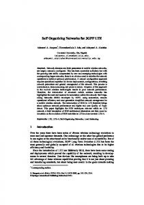
switching over to another independent WARP instruction on a stall. Computation throughput can still become I/O limited if memory bandwidth is low. Fortunately, fast on-chip resources, such as registers, shared memory and constant memory, can be used in place of off-chip device memory to keep the computation throughput high. Shared memory is especially useful. It can reduce memory access time by keeping data on-chip and reduce redundant calculations by allowing data sharing among independent threads. However, shared memory on each SM has 16 access ports. It takes one cycle if 16 consecutive threads access the same port (broadcast) or none of the threads access the same port (one to one). However, a random layout with some broadcast and some one-to-one accesses will be serialized and cause a stall. There are several other limitations with shared memory. First, only threads within a block can share data among themselves and threads between blocks can not share data through shared memory. Second, there are only (16KB) of shared memory on each stream multiprocessor and shared memory is divided among the concurrent thread blocks on an SM. Using too much shared memory can reduce the number of concurrent thread blocks mapped onto an SM. As a result, it is a challenging task to implement an algorithm that keeps the GPU cores from idling–we need to partition the workload across cores, while effectively using shared memory, and ensuring a sufficient number of concurrently executing thread blocks. III. MAP DECODING ALGORITHM The principle of Turbo decoding is based on the BCJR or MAP (maximum a posteriori) algorithms [15]. The structure of a MAP decoder is shown in Figure 1. One iteration of the decoding process consists of one pass through both decoders. Although both decoders perform the same set of computations, the two decoders have different inputs. The inputs of the first decoder are the deinterleaved extrinsic log-likelihood ratios (LLRs) from the second decoder and the input LLRs from the channel. The inputs of the second decoder are the interleaved extrinsic LLRs from the first decoder and the input LLRs from the channel. La
Lc(ys)
Decoder 0
Le
Π-1
Le+Lch
Π
La+Lch
Decoder 1
Lc(yp0) Lc(yp1)
incoming paths, one path for ub = 0 and one path for ub = 1. Let sk be a state at stage k, the branch metric (or transition probability) is defined as: γk (sk−1 , sk ) = (Lc (yks ) + La (yks ))uk + Lc (ykp )pk ,
where uk , the information bit, and pk , the parity bit, are dependent on the path taken (sk+1 , sk ). Lc (yks ) is the systematic channel LLR, La (yks ) is the a priori LLR, and Lc (ykp ) is the parity bit channel LLR at stage k. The decoder first performs
Fig. 2: 3GPP LTE turbo code trellis with 8 states a forward traversal to compute αk , the forward state metrics for the trellis state in stage k. The state metrics αk are computed recursively as the computation depends on αk−1 . The forward state metric for a state sk at stage k, αk (sk ), is defined as: αk (sk ) = max∗sk−1 ∈K (αk−1 (sk−1 ) + γ(sk−1 , sk )),
To decode a codeword with N information bits, each decoder performs a forward traversal followed by a backward traversal through an N -stage trellis to compute an extrinsic LLR for each bit. The trellis structure, or the connections between two stages of the trellis, is defined by the encoder. Figure 2 shows the trellis structure for the 3GPP LTE turbo code, where each state has two
193
(2)
where K is the set of paths that connect a state in stage k − 1 to state sk in stage k. After the decoder performs a forward traversal, the decoder performs a backward traversal to compute βk , the backward state metrics for the trellis state in stage k. The backward state metric for state sk at stage k, βk (sk ), is defined as: βk (sk ) = max∗sk+1 ∈K (βk+1 (sk+1 ) + γ(sk+1 , sk )).
(3)
Although the computation is the same as the computation for αk , the state transitions are different. In this case, K is the set of paths that connect a state in stage k + 1 to state sk in stage k. After computing βk , the state metrics for all states in stage k, we compute two LLRs per trellis state. We compute one state LLR per state sk , Λ(sk |uk = 0), for the incoming path that is connected to state sk which corresponds to uk = 0. In addition, we also compute one state LLR per state sk , Λ(sk |ub = 1), for the incoming path that is connected to state sk which corresponds to uk = 1. The state LLR, Λ(sk |ub = 0), is defined as: Λ(sk |ub = 0) = ak−1 (sk−1 ) + γ(sk−1 , sk ) + βk (sk ),
Fig. 1: Overview of turbo decoding
(1)
(4)
where the path from sk−1 to sk with ub = 0 is used in the computation. Similarly, the state LLR, Λ(sk |ub = 1), is defined as: Λ(sk |ub = 1) = ak−1 (sk−1 ) + γ(sk−1 , sk ) + βk (sk ),
(5)
where the path from sk−1 to sk with ub = 1 is used in the computation.
Host Memory
To compute the extrinsic LLR for uk , we perform the following computation: max∗sk ∈K (Λ(sk |ub = 0) − Λ(sk |ub = 1)) −La (yks ) − Lc (yks ), (6)
where K is the set�of all possible states and max∗ () is defined as max∗ (S) = ln( s∈S es ). In the next section, we will describe how this algorithm is mapped onto GPU in detail.
Lc(ys), Lc(p0), Lc(p1) 2 cycles = 1 iteration
Le (k) =
Device Memory
D0
D1
D2
…..
DP-1
Fig. 3: Overview of our MAP decoder implementation
IV. I MPLEMENTATION OF MAP DECODER ON GPU A straight-forward implementation of the decoding algorithm requires the completion of N stages of αk computation before the start of βk computation. Throughput of such a decoder would be low on a GPU. First, the parallelism of this decoder would be low; since we would spawn only one thread block with 8 threads to traverse the trellis in parallel. Second, the memory required to save N stages of αk is significantly larger than the shared memory size. Finally, a traversal from stage 0 to stage N − 1 takes many cycles to complete and leads to very long decoding delay. Figure 3 provides an overview of our implementation. At the beginning of the decoding process, the inputs of the decoder, LLRs from the channel, are copied from the host memory to device memory. Instead of spawning only one thread-block per codeword to perform decoding, a codeword is split into P subblocks and uses P independent thread blocks in parallel. We still assign 8 threads per each thread block as there are only 8 trellis states. However, both the amount of shared memory required and the decoding latency are reduced as a threadblock only needs to traverse through N P stages. After each half decoding iteration, thread blocks are synchronized by writing extrinsic LLRs to device memory and terminating the kernel. In the device memory, we allocate memory for both extrinsic LLRs from the first half iteration and extrinsic LLRs from the second half iteration. During the first half iteration, the P thread blocks read from extrinsic LLRs from the second half iteration. During the second half of the iteration, the direction is reversed. Although a sliding window with training sequence [16] can be used to improve the BER performance of the decoder, it is not supported by the current design. As the length of sub-blocks is very small with large P , a sliding window would add significant overhead. However, the next iteration initialization technique is used to improve BER performance. The α and β values between neighboring thread-blocks are exchanged between iterations. Only one MAP kernel is needed as each half iteration of the MAP decoding algorithm performs the same sequence of computations. However, since the input changes and the output changes between each half iteration, the kernel needs to be reconfigurable. Specifically, the first half iteration reads a priori LLRs and writes extrinsic LLRs without any interleaving or deinterleaving. The second half iteration reads a priori LLRs interleaved and writes extrinsic LLRs deinterleaved. The kernel handles reconfiguration easily with a couple of simple conditional reads and writes at the beginning and the end of the kernel. Therefore, this kernel executes twice per iteration. The implementation details
194
of the reconfigurable MAP kernel are described in the following subsections. A. Shared Memory Allocation To increase locality of the data, our implementation attempts to prefetch data from device memory into shared memory and keep intermediate results on die. Since the backward traversal depends on the results from the forward traversal, we save N P stages of αk values in shared memory from the forward traversal. Since there are 8 threads, one per trellis state, each thread block requires 8N P floats for α. Similarly, we need to save βk to compute βk−1 , which requires 8 floats. In order to increase thread utilization during extrinsic LLR computation, we save up to 8 stages of Λk (sk |ub = 0) and Λk (sk |ub = 1), which requires 128 floats. In addition, at the start of the kernel, we prefetch N P LLRs from the channel and N P a priori LLRs into shared memory for more efficient access. A total of 10N P + 196 floats is allocated per thread-block. Since we only have 16KB of shared memory which is divided among concurrent executing thread blocks, small P increases the amount of shared memory required per thread block which reduces the number of concurrent executing thread blocks significantly. B. Forward Traversal During the forward traversal, each thread block first traverses through the trellis to compute α. We assign one thread to each trellis level; each thread evaluates two incoming paths and updates αk (sj ) for the current trellis stage using αk−1 , the forward metrics from the previous trellis stage k−1. The decoder use Equation (2) to compute αk . The computation, however, depends on the path taken (sk−1 , sk ). The two incoming paths are known a priori since the connections are defined by the trellis structure as shown in Figure 2. Table I summarizes operands needed for α computation. The indices of the αk are stored in constant memory. Each thread loads the indices and the values pk |ub = 0 and pk |ub = 1 at the start of the kernel. The pseudo-code for one iteration of αk computation is shown in Algorithm 1. The memory access pattern is very regular for the forward traversal. Threads access values of αk−1 in different memory banks. Since all threads access the same a priori LLR and parity LLR in each iteration, memory accesses are broadcast reads. Therefore, there are no shared memory conflicts in either case, that is memory reads and writes are handled efficiently by shared memory.
TABLE I: Operands for αk computation Thread id (i) 0 1 2 3 4 5 6 7
ub = 0 sk−1 pk 0 0 3 1 4 1 7 0 1 0 2 1 5 1 6 0
traverse through the trellis and save 8 stages of Λ0 and Λ1 before performing extrinsic LLR computations. By saving eight stages of Λ0 and Λ1 , we allow all 8 threads to compute LLRs in parallel efficiently. Each thread handles one stage of Λ0 and Λ1 to compute an LLR. Although this increases thread utilization, threads need to avoid accessing the same bank when computing extrinsic LLR. For example, 8 elements of Λ0 for each stage are stored in 8 consecutive addresses. Since there are 16 memory banks, elements of even stages Λ0 or Λ1 with the same index would share the same memory bank. Likewise, this is true for even stages of Λ0 . Hence, sequential accesses to Λ0 or Λ1 to compute extrinsic LLR will result in four-way memory bank conflicts. To alleviate this problem, we permute the access pattern based on thread ID as shown in Algorithm 3.
ub = 1 sk−1 pk 1 1 2 0 5 0 6 1 0 1 3 0 4 0 7 1
Algorithm 1 thread i computes αk (i) a0 ← αk−1 (sk−1 |ub = 0) + Lc (yks ) ∗ (pk |ub = 0) a1 ← αk−1 (sk−1 |ub = 1) + (Lc (yks ) + La (k)) +Lc (psk )(pk |ub = 1) αk (i) = max∗ (a0 , a1 ) SYNC
Algorithm 3 thread i computes Le (i)
C. Backward Traversal and LLR Computation After the forward traversal, each thread block traverses through the trellis backward to compute β. We assign one thread to each trellis level to compute β, followed by computing Λ0 and Λ1 shown in Algorithm 2. The indices of βk+1 and values of pk are summarized in Table II. Similar to the forward traversal, there are no shared memory bank conflicts since each thread accesses an element of α or β in a different bank.
D. Interleaver
TABLE II: Operands for βk computation Thread id (i) 0 1 2 3 4 5 6 7
ub = 0 sk+1 pk 0 0 4 0 5 1 1 1 2 1 6 1 7 0 3 0
λ0 = Λ0 (i) λ1 = Λ1 (i) for j = 1 to 7 do index = (i + j)&7 λ0 = max∗ (λ0 , Λ0 (index)) λ1 = max∗ (λ1 , Λ1 (index)) L e = λ1 − λ0 Compute write address Write Le to device memory end for
The interleaver is used in the second half iteration of the MAP decoding algorithm. In our implementation, a quadratic permutation polynomial (QPP) interleaver [17], which is proposed in the 3GPP LTE standard was used. Although the QPP interleaver is contention free since it can guarantee bank free memory access, where each sub-block accesses a different memory bank. However, the memory access pattern is still random. Since the inputs are shared in device memory, memory accesses are not necessarily coalesced. We reduce latency by pre-fetching data into the shared memory. The QPP interleaver is defined as:
ub = 1 sk+1 pk 4 1 0 1 1 0 5 0 6 0 2 0 3 1 7 1
Π(x) = f1 x + f2 x2 Algorithm 2 thread i computes βk (i) and Λ0 (i) and Λ1 (i)
(mod N ).
(7)
Direct computation of Π(x) using Equation (7) can cause overflow. For example, 61432 can not be represented as a 32-bit integer. The following equation is used to compute Π(x) instead:
b0 ← αk+1 (sk+1 |ub = 0) + Lc (yks ) ∗ (pk |ub = 0) b1 ← αk+1 (sk+1 |ub = 1) + (Lc (yks ) + La (k)) +Lc (psk )(pk |ub = 1) βk (i) = max∗ (b0 , b1 ) SYNC Λ0 (i) = αk (i) + Lp (i)pk + βk+1 (i) Λ1 (i) = αk (i) + (Lc (k) + La (k)) + Lp (sk )pk + βk (i)
Π(x) = (f1 + f2 x
After computing Λ0 and Λ1 for stage k, we can compute the extrinsic LLR for stage k. However, there are 8 threads available to compute the single LLR, which introduces parallelism overhead. Instead of computing one extrinsic LLR for stage k as soon as the decoder computes βk , we allow the threads to
195
(mod N )) · x
(mod N )
(8)
Another alternative is to compute Π(x) recursively [6], which requires Π(x) to be computed before we can compute Π(x + 1). This is not efficient for our design as we need to compute several interleaved addresses in parallel. For example, during the second half of the iteration to store extrinsic LLR values, 8 threads need to compute 8 interleaved address in parallel. Equation (8) allows efficient address computation in parallel. Although our decoder is configured for the 3GPP LTE standard, one can replace the current interleaver function with
−1
another function to support other standards. Furthermore, we can define multiple interleavers and switch between them onthe-fly since the interleaver is defined in software in our GPU implementation.
10
E. max∗ Function Both natural logarithm and natural exponential are supported on CUDA. We support full-log-MAP as well as max-log-MAP [18]. We compute full-log-MAP by:
10
∗
max(a, b) = max(a, b) + ln(1 + e
−|b−a|
)
−2
10
Bit Error Rate (BER)
−3
−4
10
−5
10
(9)
P=1 P=32 P=64 P=96 P=128
−6
10
and max-log-MAP is defined as: (10)
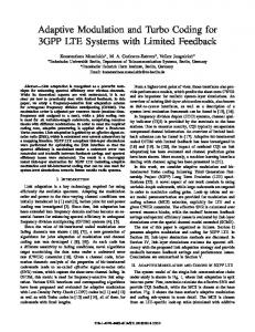
Throughput of full-log-MAP will be slower than the throughput of max-log-MAP. Not only is the number of instructions required for full-log-MAP greater than the number of instructions required for max-log-MAP, but also the natural logarithm and natural exponential instructions take longer to execute on the GPU compared to common floating operations, e.g. multiply and add. An alternative is using a lookup table in constant memory. However, this is even less efficient as multiple threads access different entries in the lookup table simultaneously and only the first entry will be a cached read. V. BER P ERFORMANCE AND T HROUGHPUT R ESULTS We evaluated accuracy of our decoder by comparing it against a reference standard C Viterbi implementation. To evaluate the BER performance and throughput of our turbo decoder, we tested our turbo decoder on a Linux platform with 8GB DDR2 memory running at 800 MHz and an Intel Core 2 Quad Q6600 running at 2.4Ghz. The GPU used in our experiment is the Nvidia TESLA C1060 graphic card, which has 240 stream processors running at 1.3GHz with 4GB of GDDR3 memory running at 1600 MHz. A. Decoder BER Performance Since our decoder can change P , which is the number of sub-blocks to be decoded in parallel, we first look at how the number of parallel sub-blocks affects the overall decoder BER performance. In our setup, the host computer first generates the random bits and encodes the random bits using a 3GPP LTE turbo encoder. After passing the input symbols through the channel with AWGN noise, the host generates LLR values which are fed into the decoding kernel running on GPU. For this experiment, we tested our decoder with P = 32, 64, 96, 128 for a 3GPP LTE turbo code with N = 6144. In addition, we tested both full-log-MAP as well as max-log-MAP with the decoder performing 6 decoding iterations. Figure 4 shows the bit error rate (BER) performance of the our decoder using full-log-MAP, while Figure 5 shows the BER performance of our decoder using max-log-MAP. In both cases, BER performance of the decoder decreases as we increase P . The BER performance of the decoder is significantly better when full-log-MAP is used. Furthermore, we see that even with parallelism of 96, where each sub-block is only 64 stages long, the decoder provides BER performance that is within 0.1dB of the performance of the optimal case (P = 1).
196
−7
10
0
0.1
0.2
0.3 0.4 Eb/No [dB]
0.5
0.6
0.7
Fig. 4: BER performance (BPSK, full-log-MAP) 0
10
−1
10
−2
10 Bit Error Rate (BER)
∗
max(a, b) = max(a, b).
−3
10
−4
10
−5
10
−6
10
−7
10
0
P=1 P=32 P=64 P=96 P=128 0.1
0.2
0.3 0.4 Eb/No [dB]
0.5
0.6
0.7
Fig. 5: BER performance (BPSK, max-log-MAP)
B. Decoder Throughput We measure the time it takes for the decoder to decode a batch of 100 codewords using event management in the CUDA runtime API. The runtimes measured include both memory transfers and kernel execution. Since our decoder can support various code sizes, we can decode N = 64, 1024, 2048, 6144 with various numbers of decoding iterations and parallelism P . The throughput of the decoder is only dependent on W = N P as decoding time is linearly dependent on the number of trellis stages traversed. Therefore, we report the decoder throughput as a function of W which can be used to find the throughput of different decoder configurations. For example, if N = 6144, P = 64, and the decoder performs 1 iteration, the throughput of the decoder is the throughput when W = 96. The throughput of the decoder is summarized in Table III. We see that the throughput of the decoder is inversely proportional to the number of iterations performed. The throughput of the decoder after m iterations can be approximated as T0 /m, where T0 is the throughput of the decoder after 1 iteration. Although throughput of full-log-MAP is slower than max-logMAP as expected, the difference is small while full-log-MAP
TABLE III: Throughput vs W # Iter 1 2 3 4 5 6
Max-log-MAP W=32 49.02/36.59 24.14/18.09 16.01/12.00 11.98/9.01 9.57/7.19 7.97/5.99
throughput/ Full-log-MAP throughput (Mbps) W=64 W=96 W=128 34.75/23.87 26.32/19.50 17.95/12.19 17.09/12.72 12.98/9.62 8.82/5.59 11.34/8.45 8.57/6.39 5.85/3.97 8.48/6.51 6.41/4.78 4.37/2.97 6.77/5.2 5.12/3.82 3.49/2.37 5.64/4.33 4.26/3.18 2.91/1.97
improves the BER performance of the decoder significantly. Therefore, full-log-MAP is a better choice for this design. C. Architecture Comparison Table IV compares our decoder with other programmable turbo decoders. Our decoder with W = 64 compares favorably in terms of throughput and BER performance. We can support both the full-log-MAP (FLM) algorithm and the simplified max-logMAP (MLM) algorithm while most other solutions only support the sub-optimal max-log-MAP algorithm. TABLE IV: Our decoder vs other programmable turbo decoders Work [19] [20] [20] [21] [22] [5] ours
Architecture Intel Pentium 3 Motorola 56603 STM VLIW DSP TigerSHARC DSP TMS320C6201 DSP 32-wide SIMD Nvidia C1060
MAP Algorithm MLM/FLM MLM FLM MLM MLM MLM MLM/FLM
Throughput 366 Kbps/51Kbps 48.6 Kbps 200 Kbps 2.399 Mbps 500 Kbps 2.08 Mbps 6.77/5.2Mbps
Iter. 1 5 5 4 4 5 5
VI. C ONCLUSION In this paper, we presented a 3GPP LTE compliant turbo decoder implemented on GPU. We portion the workload across cores on the GPU by dividing the codeword into many subblocks to be decoded in parallel. Furthermore, all computation is completely parallel for each sub-block. To reduce the memory bandwidth needed to keep the cores fed, we prefetch data into shared memory and keep immediate data in shared memory. As different sub-block sizes can lead to BER performance degradation, we presented how both BER performance and throughput is affected by sub-block size. We show that our decoder provides faster throughput even though the full-logMAP algorithm is used. As the decoder is done in software, we can easily change the QPP interleaver and trellis structure states to support other codes. Future work includes other partitioning and memory strategies to improve throughput of the decoder. Furthermore, we will implement a completely iterative MIMO receiver by combining this decoder with a MIMO detector on the GPU. R EFERENCES [1] C. Berrou, A. Glavieux, and P. Thitimajshima, “Near Shannon limit error-correcting coding and decoding: Turbo-Codes,” in IEEE International Conference on Communication, May 1993. [2] D. Garrett, B. Xu, and C. Nicol, “Energy efficient turbo decoding for 3G mobile,” in International symposium on Low power electronics and design. ACM, 2001, pp. 328–333. [3] M. Bickerstaff, L. Davis, C. Thomas, D. Garrett, and C. Nicol, “A 24Mb/s radix-4 logMAP turbo decoder for 3GPP-HSDPA mobile wireless,” in IEEE Int. Solid-State Circuit Conf. (ISSCC), Feb. 2003.
197
[4] M. Shin and I. Park, “SIMD processor-based turbo decoder supporting multiple third-generation wireless standards,” IEEE Trans. on VLSI, vol. vol.15, pp. pp.801–810, Jun. 2007. [5] Y. Lin, S. Mahlke, T. Mudge, C. Chakrabarti, A. Reid, and K. Flautner, “Design and implementation of turbo decoders for software defined radio,” in IEEE Workshop on Signal Processing Design and Implementation (SIPS), Oct. 2006. [6] Y. Sun, Y. Zhu, M. Goel, and J. R. Cavallaro, “Configurable and Scalable High Throughput Turbo Decoder Architecture for Multiple 4G Wireless Standards,” in IEEE International Conference on Application-Specific Systems, Architectures and Processors (ASAP), July 2008, pp. 209–214. [7] P. Salmela, H. Sorokin, and J. Takala, “A Programmable Max-LogMAP Turbo Decoder Implementation,” Hindawi VLSI Design, vol. vol.2008, pp. pp. 636–640, 2008. [8] C.-C. Wong, Y.-Y. Lee, and H.-C. Chang, “A 188-size 2.1mm2 reconfigurable turbo decoder chip with parallel architecture for 3GPP LTE system,” in 2009 Symposium on VLSI Circuits, June 2009, pp. 288–289. [9] G. Falcão, V. Silva, and L. Sousa, “How GPUs Can Outperform ASICs for Fast LDPC Decoding,” in ICS ’09: Proceedings of the 23rd International Conference on Supercomputing, pp. 390–399. [10] M. Wu, S. Gupta, Y. Sun, and J. R. Cavallaro, “A GPU Implementation of A Real-Time MIMO Detector,” in IEEE Workshop on Signal Processing Systems (SiPS’09), Oct. 2009. [11] M. Wu, Y. Sun, and J. R. Cavallaro, “Reconfigurable Real-time MIMO Detector on GPU,” in IEEE 43rd Asilomar Conference on Signals, Systems and Computers (ASILOMAR’09), Nov. 2009. [12] Xilinx Corporation, 3GPP LTE Turbo Decoder v2.0, 2008. [Online]. Available: http://www.xilinx.com/products/ipcenter/DODI-TCCDEC-LTE.htm [13] K. Amiri, Y. Sun, P. Murphy, C. Hunter, J. R. Cavallaro, and A. Sabharwal, “Warp, a unified wireless network testbed for education and research,” in MSE ’07: Proceedings of the 2007 IEEE International Conference on Microelectronic Systems Education, June 2007. [14] NVIDIA Corporation, CUDA Compute Unified Device Architecture Programming Guide, 2008. [Online]. Available: http://www.nvidia.com/object/cuda_develop.html [15] L. Bahl, J. Cocke, F. Jelinek, and J. Raviv, “Optimal Decoding of Linear Codes for Minimizing Symbol Error Rate,” IEEE Transactions on Information Theory, vol. IT-20, pp. 284–287, Mar. 1974. [16] F. Naessens, B. Bougard, S. Bressinck, L. Hollevoet, P. Raghavan, L. V. der Perre, and F. Catthoor, “A unified instruction set programmable architecture for multi-standard advanced forward error correction,” in IEEE Workshop on Signal Processing Systems(SIPS), October 2008. [17] J. Sun and O. Takeshita, “Interleavers for turbo codes using permutation polynomials over integer rings,” IEEE Trans. Inform. Theory, vol. vol.51, pp. 101–119, Jan. 2005. [18] P. Robertson, E. Villebrun, and P. Hoeher, “A comparison of optimal and sub-optimal MAP decoding algorithm operating in the log domain,” in IEEE Int. Conf. Commun., 1995, pp. 1009–1013. [19] M. Valenti and J. Sun, “The UMTS Turbo Code and a Efficient Decoder Implementation Suitable for Software-Defined Radios,” International Journal of Wireless Information Networks, vol. 8, no. 4, pp. 203–215, Oct. 2001. [20] H. Michel, A. Worm, M. Munch, and N. Wehn, “Hardware software trade-offs for advanced 3G channel coding,” in Proceedings of Design, Automation and Test in Europe, 2002. [21] K. Loo, T. Alukaidey, and S. Jimaa, “High performance parallelised 3GPP turbo decoder,” in IEEE Personal Mobile Communications Conference, April 2003, pp. 337–342. [22] Y. Song, G. Liu, and Huiyang, “The implementation of turbo decoder on DSP in W-CDMA system,” in International Conference on Wireless Communications, Networking and Mobile Computing, Dec. 2005, pp. 1281–1283.


![3GPP LTE: An Overview - IAENG [PDF]](https://m.moam.info/img/260x300/3gpp-lte-an-overview-iaeng-pdf_648406b4098a9ec44c8b458d.jpg)