Implementation of A High-Speed Parallel Turbo Decoder for 3GPP LTE Terminals Di Wu, Rizwan Asghar, Yulin Huang and Dake Liu Abstract — This paper presents a parameterized parallel Turbo decoder for 3GPP LTE terminals. To support the high peak data-rate defined in the forthcoming 3GPP LTE standard, Turbo decoder with a throughout beyond 150Mbit/s is needed as a key component of the radio baseband chip. By exploiting the tradeoff of precision, speed and area consumption, a Turbo decoder with eight parallel SISO units is implemented to meet the throughput requirement. The turbo decoder is synthesized, placed and routed using 65nm CMOS technology. It achieves a throughput of 152Mbit/s and occupies an area of 0.7mm2 with estimated power consumption being 650mW1. Index Terms — Turbo, 3GPP, ASIC.
I. INTRODUCTION The ever increasing need of high-speed mobile data service has fostered the deployment of various mobile broadband technologies such as 3rd Generation Partnership Project LongTerm Evolution (3GPP-LTE). In order to provide mobility as well as reliability of the data transmission over error-prone radio channels, forward-error correction (FEC) codes, which add redundant information before transmitting the data, are indispensable to achieve robust data transmission. Among them, Turbo codes [1] have been widely adopted by different standards owing to its capability of approaching the Shannon limit. Meanwhile, since the amount of operations involved in Turbo decoding is significant, it has always been the bottleneck of these wireless systems which are latency constrained. Hybrid Automatic Repeat ReQuest (H-ARQ) [2] has been introduced in LTE to improve the throughput by retransmitting corrupted packets and applying soft-combining at the receiver side. With the aid of H-ARQ, link-level throughput can be significantly improved even in presence of mild bit-error-rate (BER). Therefore, when benchmarking the performance of Turbo decoding for design trade-off (performance vs. complexity), it is not enough to only consider a plain AWGN channel without standard compliant parameters. Especially H-ARQ needs to be taken into consideration at the same time. 1 The work is supported by European Commission through the EU-FP7 Multi-base project with Ericsson AB, Infineon Austria AG, IMEC, Lund University and KU-Leuven. D. Wu, R. Asghar, and D. Liu are with Department of Electrical Engineering, Linköping University, 58183 Linköping, Sweden (e-mail:
[email protected],
[email protected],
[email protected]) Y. Huang was with Department of Electrical Engineering, Linköping University, 58183 Linköping, Sweden.
TABLE I SUPPORTED LTE UE CATEGORIES UE Category (CAT)
1
Supported Bandwidth
2
3
4
1,4,3,5,10,15,20 MHz
Antenna Configurations
Up to 2x2 SM and SFBC
Num of Layers for SM
1
Max num of Soft-bits
250368
1237248
1237248
1827072
DL peak rate (Mbit/s)
10
50
100
150
UL peak rate (Mbit/s)
5
25
50
50
2
In [3] a programmable baseband processor is presented to accommodate the symbol processing of various emerging wireless standards (e.g. LTE and WiMAX) by simply reloading the firmware. However, computational intensive parts such as the Turbo decoder need to be implemented as ASIC for the sake of silicon and power efficiency. In this paper, a parallel Turbo decoder is implemented as an accelerator attached to the baseband processor to meet the physical layer requirements of up to Category 4 user equipment (UE) as listed in TABLE I. Standard compliant link-level simulation is carried out to verify the performance of the decoder with H-ARQ taken into account. The remainder of the paper is organized as follows. In Section II the architecture of the decoder is presented. Section III presents the simulation performance of the Turbo decoder. The ASIC implementation is presented in Section IV. Finally, Section V concludes the paper. II. PARALLEL TURBO DECODER ARCHITECTURE According to the definition of LTE parameters in TABLE I, up to 150Mbit/s peak data rate for downlink needs to be supported. With the state-of-the-art Turbo decoder (e.g. [4]) that contains a single soft-input soft-output (SISO), the maximum throughput that can be achieved with a clock frequency of 300MHz is around 25Mbit/s. Hence a new parallel Turbo decoder is needed to supply higher data rates. The way to achieve high data-rate Turbo decoding is to parallelize the decoder efficiently while maintaining sufficient decoding performance. However, the existing WCDMA interleaver will incur memory conflicts when several SISO units are in parallel accessing different parts of the coded block which prohibits the straightforward parallelization. Fortunately, a contention-free interleaver has been introduced in LTE [2] which allows multiple SISO to access different sub-blocks in parallel. This brings the opportunity of lowcomplexity parallel implementation of the decoder. Although Turbo decoders based on SIMD architectures [6] exist, they are not competitive compared to dedicated
implementations. Furthermore, since the variation of Turbo decoding procedure among different standards is small, a parameterized Turbo decoding accelerator is sufficient to achieve enough flexibility while maintaining area and power efficiency. In order to supply 150Mbit/s peak data rate required by LTE UE category 4, a parallel Turbo decoder with eight SISO units has been designed with its architecture depicted in Fig. 1.
Fig. 1.
values at the beginning and end of sliding windows and parallel windows need to be saved which means the overhead is limited. A. SISO Unit SISO unit is the major block in a Turbo decoder. The input to the SISO are: systematic a-prior information λ aks, systematic intrinsic information λ iks and parity intrinsic information λ ikp . In each SISO, classical sliding-window processing is applied to reduce the latency. In this paper, the size of the sliding window S sw is 64. Each SISO unit consists of α , β , γ and LogLikelihood Ratio (LLR) units. Radix-2 log-Max decoding is used with the scaling of the extrinsic information which allows a close log-MAP decoding performance to be achieved. The scaling factor ranges from 0.6 to 0.8.
Block Diagram of the Parallel Turbo Decoder Fig. 3.
Block Diagram of the SISO Unit
• γ Unit: As depicted in Fig. 4(a), the γ units computes two transition metrics γ 10 = λ aks + λ iks , γ 11 = λ aks + λ iks + λ ikp (with γ 00 = 0 and γ 01 = λ ikp ) from the input. • α unit: α unit computes the forward state metrics 1
α km = max α kb−( 1j , m )γ kj−,b1( j ,m ) j =0
Fig. 2.
Scheduling Chart of a Half Iteration
As defined in [2], the maximum code block size is 6144 in LTE which will incur very high latency when serial Turbo decoder is used. A super windowing strategy [5] is adopted in this paper to speed up the decoding. First, the coded block will be partitioned into eight equally sized sub-blocks. Each SISO unit is responsible for the processing of one sub-block. The processing of one sub-block is considered as one parallel window with size S pw . Hence in total eight parallel windows can be processed in parallel, which reduced the processing time by eight times. The challenge when using parallel window is the absence of initial values at the border of each parallel window. As depicted in Fig. 1 and Fig. 3, a method namely Next Iteration Initialization (NII) [7] is used to estimate the initial values both sliding windows and parallel windows using the corresponding state metrics produced at previous iteration. This requires extra storage of α and β values. These values are saved in a first-in first-out (FIFO) between neighboring SISO units and the local buffer inside each SISO. Therefore, the reduction of computational latency is at the cost of increased storage. Fortunately, only α and β
for each sub-block assigned to the SISO with size S pw . The result will be saved into a stack memory, from where, the β unit will read in a reversed order to compute the backward metrics. The α unit consists of mainly eight add-compareselect (ACS) units as depicted in Fig. 4(b).
Fig. 4.
γ and ACS Units
• β unit: Similar to α unit, β unit also consists of eight ACS units. It computes the backward metrics 1
β km = max γ kj , m β kf+(1j ,m ) j =0
based on the result computed early by the γ unit. Here f ( j , m ) is the next state in the trellis when the input is j and current state being m . As NII method is used, the computed β values at the border of the sliding windows will be stored in a buffer to be used as initial value in the
next iteration. Intermediate values γ kj , m β kf+(1j , m ) which are computed half-way to get β km will be passed directly to the LLR unit to compute the extrinsic information Λ (d k ). • LLR unit: It computes the extrinsic information m) Λ (d k ) = max (α km + γ k1, m + β kf+(1, ) − max (α km + γ k0,m + β kf+(0,1 m) ) 1 7
7
m =0
m =0
and the soft-output based on the result from α unit and β unit. As the output of the SISO units, Λ (d k ) is passed through the switch network to different memory banks for later access by the SISO unit in the next iteration. g_c f2 >>1
g_x_b
1 0
K
msb
AM +
1 0
R
g(0)
0
Fig. 5.
S1
S2
S3
K
S
AM +
R
A
g_x_a
+
–
g_x
S4
S5
S6
S7
P1
P2
P3
P4
P5
P6
P7
P8
A1
A2
A3
A4
A5
A6
A7
A8
Parallel Interleaver Architecture
achieved with the replication of the hardware for basic interleaver and getting support from a LUT providing the starting values. In this case a total of 32 additions are needed. However, for the sake of hardware reuse, part of the basic interleaver unit can be shared to generate multiple addresses at the same time. The optimized hardware uses 18 additions in total to generate 8 parallel interleaver addresses, thus saving 14 additions. The hardware for parallel interleaver address generation for LTE is shown in Fig. 5.
C. H-ARQ In LTE, two soft-combining methods namely Chase Combining (CC) and Incremental Redundancy (IR) are supported. In this paper, only CC is considered. The base station retransmits the same packet when it receives the NACK signal from UE, and UE combines the LLR information generated by the detector with those of the initially received packet. The gain of H-ARQ is at the cost of larger soft buffer used to store the demodulated soft information. In order to support the buffer size as large as 1.8Mbits, high-density memory such as 1T-SRAM needs to be used. Since 1T-SRAM is different from the technology used for the decoder, it is not included in the results of this paper. −1
10
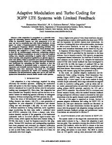
B. Parallel Interleaver
−2
10
A( x ) = ( f1 i x + f 2 i x 2 ) % K
−3
10
BER
The internal interleaver involved with the Turbo Code in 3GPP-LTE is based on quadratic permutation polynomial (QPP). Thanks to the QPP interleaver [2] which allows conflict-free parallel access, the implementation of the parallel interleaver is straight-forward. In this paper, to support the parallel Turbo decoder, a configurable parallel interleaver is adopted. It can generate eight addresses in parallel for the data access of eight SISO units. QPP interleavers have very compact representation methodology and also inhibit a structure that allows the easy analysis for its properties. The interleaving function for turbo code is specified by the following quadratic permutation polynomial:
−5
10
−6
10
(
)
Fig. 6.
20
22
24
26 SNR [dB]
28
30
32
30
32
Bit-Error-Rate (rate 0.926, 64-QAM)
(1)
40 35
throughput [Mbit/s]
30 25 20 15 10 5
(2)
Where g ( x ) = ( f1 + f 2 + 2. f 2 .x ) % K , which can also be computed recursively as g ( x +1) = ( g ( x ) + 2. f 2 ) % K . The two recursive terms I ( x +1) and g ( x +1) are easy to compute and they provide the basic interleaver functionality for LTE. Owing to the parallelism inherited in the QPP interleaver, the generation of parallel interleaver addresses can be
uncoded BER coded BER Parallel Turbo coded BER Serial Turbo
−7
10
Here x = 0,1, 2, … ( K − 1) , where K is the block size. This polynomial provides deterministic interleaver behavior for different block sizes with appropriate values of f1 and f 2 . Direct implementation of the permutation polynomial given in eq. (1) is in-efficient due to multiplications, modulo function and bit growth problem. The simplified hardware solution is to use recursive approach adopted in [8] and [9]. Eq. (1) can be re-written for recursive computation as: A( x +1) = A( x ) + g ( x ) % K
−4
10
0 20
Fig. 7.
coded throughput Serial Turbo coded throughput Parallel Turbo uncoded throughput 22
24
26 SNR [dB]
28
Link-level Throughput (rate 0.926, 64-QAM)
III. SIMULATION AND SYSTEM PERFORMANCE In order to benchmark the parallel Turbo decoder, simulation is carried out based on a 3GPP LTE link-level
simulator. The simulator is compatible to 3GPP specification defined in 36.211 and 36.212 [2]. The 3GPP SCME model [10] is used as the channel model. In the simulation, 5000 subframes have been simulated. 64-QAM modulation and 5/6 coding rate is used. Soft-output sphere decoder which achieves ML performance is used as the detection method. No close-loop precoding is assumed. At most three retransmissions are allowed in the CC based H-ARQ. Simulation results are depicted in Fig. 6 and Fig. 7. Note that in the simulation, only 5MHz band is used instead of 20MHz band for the maximum throughput. The link-level BER and throughput figures show that the performance degradation introduced by the approximations (e.g. the NII based approximation) adopted in the parallel decoder is very small.
TABLE II COMPARISON OF ASIC IMPLEMENTATION RESULTS Turbo Decoder Technology Supply Voltage Logic Size Total Memory Total Area Working Frequency Throughput Estimated Power Silicon Area/Throughput Power Efficiency
This Work CMOS 65nm 1.2V 70kgate 250kb 0.7mm2 250MHz 152Mbps 650mW 0.005 mm2/Mbps 0.71nJ/b/iter
[4] CMOS 130nm 1.2V 44.1kgate 120kb 1.2mm2 246MHz 10.8Mbps 32.4mW 0.11 mm2/Mbps 0.54nJ/b/iter
The Turbo decoder is implemented using 65nm CMOS process from STMicroelectronics. After placement and routing, it easily runs at 250MHz with a core area of 0.7mm2. The throughput of the Radix-2 parallel decoder can be computed as: T=
Sblk ,max × f clk
( S pw,max + Ssw + Cextra ) × 2 × Nite
where S pw,max =
Sblk ,max N siso
(3)
. Here Sblk ,max = 6144 is the maximum
number of bits per codeword defined in [2], N siso = 8 is the number of SISO units, S sw = 64 is the sliding window size, Cextra = 10 is the number of overhead cycles, f clk = 250 MHz is the clock frequency and N ite is the number of decoding iterations. The throughput of the decoder is 152Mbit/s in case N ite = 6 . In high SNR region, early stopping can effectively reduce the number of iterations needed to four. This gives a throughput of 228Mbit/s. Theoretically, for 20MHz bandwidth with 2 × 2 Spatial Multiplexing and 64-QAM, the required throughput of Turbo decoding is 176Mbit/s, which means the presented implementation is sufficient for CAT4 PDSCH decoding. Owing to the scalability of the on-chip network in [3], the Turbo decoder can be easily wrapped and integrated with the programmable platform. TABLE II depicts the ASIC implementation result in comparison to the prior-art presented in [4]. The result shows that work in this paper achieves more than 10 times data throughput compared to [4] while achieving higher silicon efficiency and slightly lower power efficiency even without the voltage scaling used in [4]. V. CONCLUSION
In this paper, a 650mW Turbo decoder is presented for CAT4 LTE terminals. The design is based on algorithm/architecture co-optimization targeting a good tradeoff between performance and throughput. The result shows that at feasible silicon cost, the parallel architecture significantly reduces the decoding latency while allowing a link-level performance that is close to the traditional serial decoder to be achieved.
S8
S1
Interleaver
IV. ASIC IMPLEMENTATION S7
S6
S2
S3
S5
S4
Control
Fig. 8.
Layout of the Turbo Decoder
VI. ACKNOWLEDGMENT
The authors would like to thank Christian Mehlführer and the Christian Doppler Laboratory for Design Methodology of Signal Processing Algorithms at Vienna University of Technology, for contributions on the simulators. REFERENCES [1]
C. Berrou, A. Glavieux, and P. Thitimajshima, “Near Shannon limit error-correcting coding and decoding: Turbo Codes,” in Proc. IEEE ICC, 1993, pp. 1064-1070. [2] 3GPP, “Tech. Spec. 36.212 V8.4.0, E-UTRA; Multiplexing and Channel Coding,” Sept 2008. [3] Nilsson, E. Tell, and D. Liu, “An 11 mm2 70 mW Fully-Programmable Baseband Processor for Mobile WiMAX and DVB-T/H in 0.12µm CMOS,” in IEEE Journal of Solid-State Circuits, vol. 44, no. 1, pp. 9097, 2009. [4] Benkeser, A. Burg, T. Cupaiuolo, Q. Huang, “Design and Optimization of an HSDPA Turbo Decoder ASIC,” in IEEE Journal of Solid-State Circuits, vol. 44, no. 1, pp. 98-106, 2009. [5] S.Yoon, and Y. Bar-Ness, “A Parallel MAP Algorithm for Low Latency Turbo Decoding,” in IEEE Communication Letters, vol 6, pp. 288-290, July, 2002. [6] M.C. Shin and I.C. Park. “SIMD processor-based Turbo decoder supporting multiple third-generation wireless standards,” in IEEE Trans. on VLSI, vol.15, pp. 801-810, June 2007. [7] A.Dingninou, F. Raouafi, and C. Berrou, “Organisation de la memoire dans un turbo decodeur utilisant l'algorithm SUB-MAP,” in Proceedings of Gretsi, pp. 71-74, Sept. 1999. [8] R. Asghar, D. Liu, “Dual standard re-configurable hardware interleaver for turbo decoding,” in Proceedings of IEEE ISWPC, May 2008, pp. 768 - 772. [9] R. Asghar, D. Wu, J. Eilert and D. Liu, “Memory Conflict Analysis and Implementation of a Re-configurable Interleaver Architecture Supporting Unified Parallel Turbo Decoding,” in Journal of Signal Processing Systems; DOI: 10.1007/s11265-009-0394-8. To Appear. [10] D. S. Baum, J. Salo, M. Milojevic, P. Kyöti, and J. Hansen “MATLAB implementation of the interim channel model for beyond-3G systems (SCME),” May 2005.