1272
IEEE ANTENNAS AND WIRELESS PROPAGATION LETTERS, VOL. 12, 2013
Implementation of a Dual-Interrogation-Mode Embroidered RFID-Enabled Strain Sensor M. Hasani, Student Member, IEEE, A. Vena, Member, IEEE, L. Sydänheimo, Member, IEEE, L. Ukkonen, Member, IEEE, and M. M. Tentzeris, Fellow, IEEE
Abstract—This letter studies a dual-interrogation-mode (hybrid chip-enabled/chipless) technique to detect an embroidered radio frequency identification (RFID)-enabled sensor. We have created a hybrid RFID strain sensor utilizing both chipped and chipless approaches. A comparison between the read-range extraction technique, which relies upon the detection of the threshold power that is required to activate an RFID IC, and a radar-cross-section (RCS)-based technique that does not require any protocol is presented. An embroidered RFID sensor with an electrical length that is directly linked to the applied strain is realized and interrogated using both techniques. The sensitivities for the chipless radar technique and for the chip-enabled read range extraction technique are 0.66% and 0.43% frequency shift, respectively, for 1% strain variation. Simulations and measurements validate the dual interrogation mode and provide the proof of concept that a chip-enabled RFID sensor tag can be detected accurately utilizing backscattering RCS measurements. Index Terms—Chip, chipless, embroidery strain sensors, radar cross section (RCS), radar technique, radio frequency identification (RFID), stress, wireless sensors.
I. INTRODUCTION
R
ADIO frequency Identification (RFID)-enabled sensors [1], [2] have become increasingly popular over recent years. Passive RFID sensors do not require external battery supplies and offer a power-efficient alternative to battery-operated wireless sensors. These passive sensors work by harvesting electromagnetic (EM) energy from the transmitter antenna and hence decrease the overall maintenance cost that is usually due to the need for replacement of battery cells in commonly utilized ID transponders. This makes passive RFID-enabled sensor systems attractive for various fields from medical science and logistics to monitoring of environmental parameters. In this letter, we present a dual-interrogation-mode RFID-enabled strain sensor tag that can be detected using both chipped and chipless techniques. A chip-enabled passive RFID platform is composed of an IC connected to an antenna with a matching
Manuscript received June 11, 2013; revised August 09, 2013; accepted September 19, 2013. Date of publication September 25, 2013; date of current version October 11, 2013. This work was supported by the Finnish Funding Agency for Technology and Innovation, the Academy of Finland, and the Centennial Foundation of Finnish Technology Industries. M. Hasani, A. Vena, L. Sydänheimo, and L. Ukkonen are with the Tampere University of Technology, 33720 Tampere, Finland (e-mail:
[email protected];
[email protected];
[email protected];
[email protected]). M. M. Tentzeris is with the Georgia Institute of Technology, Atlanta, GA 30332-250 USA (e-mail:
[email protected]). Color versions of one or more of the figures in this letter are available online at http://ieeexplore.ieee.org. Digital Object Identifier 10.1109/LAWP.2013.2283539
circuit. To make an RFID tag sensitive to a physical parameter, the technique is to make either the antenna or the matching circuit’s electrical/electromagnetic performance sensitive to change of the sensed parameter. For some gas or humidity sensors [3], the sensing technique consists of the deposition of a film of a sensitive material with a complex permittivity value varying as a function of the concentration of the physical parameter to detect. For numerous antenna-based strain sensors, the electrical length of the antenna changes depending on the strain value [4]. Finally, in both cases, using an RFID reader operating within the UHF band, the detection technique usually relies on the detection of the threshold received power for several frequency points selected in the ISM band [3]. As a result, the detection of passive RFID-enabled sensors is based on a query command that is sent for several power values and frequency points in order to recover the sensed information. The chipless technique studied in this letter is based on a radar approach in order to detect the performance variation and sensitivity of an embroidered RFID-enabled strain sensor. The technique relies on the measurement of the static radar cross section (RCS) [5] of a chipped RFID-enabled sensor within the UHF band without the need of the use of any protocol. As one example of utilizing the proposed “dual-interrogation-mode” approach is acquiring the ID of the sensor with the protocol-based technique, and the sensed parameter with the radar technique. To validate the proposed hybrid (dual interrogation mode) concept, we implement a strain sensor for which a strong deviation of the peak-power frequency can be observed when subject to a pulling force. As shown in [6] and [7], strain sensors have a promising future in structural health monitoring applications, and it has been already proved in [5] that they can be realized with various processes, such as embroidery on stretchable fabrics. As an example, this technology authorizes deployments of large surface of textiles covered by numerous strains sensors to sense cracks or deformations on civilian building such as monuments and bridges.
II. DESIGN OF PASSIVE SEWN STRAIN SENSOR The aim of this letter is to design a strain RFID-enabled sensor with the help of embroidery technique on fabric. As it is shown in Fig. 1(a), a dipole-type antenna has been utilized. The design is quite simple, and the utilization of the T-match technique gives a good matching between the IC and antenna for a reasonably short antenna length. Moreover, this design allows achieving about 4 m read range, which is sufficient for the remote reading of a wireless sewn strain sensor [8]. The IC that is selected for the tag is NXP UCODE G2iL SL3S1203AC0 at 915 MHz. with impedance of
1536-1225 © 2013 IEEE
HASANI et al.: DUAL-INTERROGATION-MODE EMBROIDERED RFID-ENABLED STRAIN SENSOR
Fig. 1. RFID-enabled strain sensor: (a) layout and (b) sewn prototype.
1273
Fig. 2. Read range of tag obtained with CST MWS for various strains.
A. Fabrication of Tag To embroider the antenna on the fabric material, the Husqvarna VIKING computer-aided sewing machine has been used. The antenna layout is embroidered on a polyester-based stretchable fabric that has repeatable properties after several uses [9]. The conductive thread used in the sewing of the antenna is Shieldex 110f34 dtex 2-ply HC. The conductivity of the sewed antenna depends on the sewing pattern, stitch density, and conductivity of the electric-thread [8]. Fig. 1(b) shows the sewed tag consisting of the antenna and the IC. B. Simulation of Tag The sewn strain sensing tag was initially simulated using CST Microwave Studio (MWS). With the help of previous studies reported in [8], this design has been optimized based on the fabric parameters and conductive loss of silver threads. The stretchable fabric with the thickness of 1 mm and at 1 GHz, at 1 GHz has been used as the substrate material. The complex permittivity was extracted using the Agilent dielectric probe kit 85070E, which is explained in detail in [8]. The conductive thread is modeled as an ohmic-sheet type of a material with the resistance 1.2 /sq to achieve a good agreement with the measured results [9]. When the tag is stretched longitudinally outwards, the antenna’s electrical length increases, and the resonant frequency decreases. To accurately quantify this electrical length variation, two different parameters of the tag have been simulated and compared: the read range and the RCS. These parameters are extracted using two different techniques as it will be shown in Section III. Fig. 2 shows the simulation result for the theoretical read range of the tag, which depends on the power reflection coefficient and can be calculated using Friis equation as in [10]. For the calculation, we used an equivalent isotropic radiated power of 3.28 W and a chip threshold power of 18 dBm. The simulation results indicate that the read range of the tag increases by increasing the length of the antenna. Although a performance deterioration is expected for mm because of mismatch effect, the dominant impact of the RCS (over the mismatch effect) gives higher read range for mm. There is also a frequency shift for the maximum range values. This behavior is due to the variation of the antenna length and impedance. Fig. 3 shows the simulated RCS of the same tag corresponding to a normally incident plane wave. This last result
Fig. 3. Simulated RCS with the CST MWS for various strains in vertical polarization.
relies upon a monostatic radar technique. The change of the length of antenna is also detectable in the RCS graph. Moreover, the frequency shift for the maximum RCS values is clearly visible in the RCS plot. Comparing the simulation results shows that both read range and RCS can be used for the sensing of strain variations of the sensor. III. MEASUREMENT RESULTS The performance of the sewn sensors has been experimentally characterized using two different techniques. The first (“chip-enabled”) technique relies upon the extraction of the read range with the help of an RFID reader. The second (“chipless”) is based on a monostatic radar technique with a vector network analyzer connected to an antenna. A. Tagformance Measurement System The read range of the tag has been measured with the Tagformance RFID measurement system. Tagformance is a bistatic reader unit containing a RF generator and an RF receiver with sensitivity of 80 dBm. The reader offers a transmitted output power of 3–27.8 dBm over the frequency range of 800 MHz–1 GHz. One of the most important measurement features of Tagformance software is threshold sweep, which calculates the minimum power level that is required to activate a tag. Practically, the software does a frequency sweep from 800 to
1274
IEEE ANTENNAS AND WIRELESS PROPAGATION LETTERS, VOL. 12, 2013
Fig. 5. Read range of the tag varies by increasing the length of the tag.
Fig. 5 shows the measured read range of the tag obtained with the Tagformance setup. The measurement results are well correlated with simulation results. The effect of the length variation on the read range values and the frequency of the peak are observed in both cases Fig. 5 also indicates the variation of the antenna length as a function of the longitudinally applied strain. Strain is denoted as , where is difference length due to the strain and is the initial “zero-strain” length. Typically, the strain is unitless and is expressed in percentage or microstrain . Fig. 4. (a) Tag is placed in front of the reader antenna of Tagformance measurement system. (b) Tag is placed in front of the horn antenna that is connected to the VNA.
1000 MHz with adjustable steps (i.e., 5 MHz). At each frequency, the transmit power is varying in 0.1-dB steps (or in 0.5- and 1-dB steps) to find the lowest power for which the tag is responding. Thus, the transmitted power required to activate the tag varies with frequency, and it is named as . To make the measurement results independent of the measurement setup, a calibration process is performed using a reference tag that is aligned to match the polarization of the reader antenna. The calibration provides the required information (such as path loss of the measurement channel ) to measure the maximum forward link read range, that is given as (1) To measure the read range of the sewn tag for different lengths of the antenna, as it is shown in Fig. 4(a), the tag is placed on top of a Styrofoam spacer, and simple pins have been used to stretch the fabrics, subsequently modifying the length. After adjusting the length of the antenna to a specific value, the read range of tag has been measured by placing the tag at 40 cm from the transmitter antenna inside a shielded and anechoic chamber. Based on the technical data of measurement cabinet, 40 cm is the standard measurement distance between the wideband antenna and tag. Even if measurements have been performed inside anechoic chamber, by experience, it is verified that detection of the read range variation in indoor environment, where multipath has strong effect, is possible as long as the background environment does not change as function of time.
B. VNA Measurement Setup The RCS variation of the strain sensors has been measured using a frequency-domain measurement setup. For this purpose, the tag is placed on a mechanical stretching test bench at the distance of 20 cm from the horn antenna [9]. The dual-polarization wideband horn antenna ETS Lindgren 3164-04 is connected to a two-port vector network analyzer (VNA) Agilent PNA E8358A. The power delivered by the VNA is 5 dBm in the frequency band 750 MHz–1 GHz. Fig. 4(b) shows the tag in measurement setup in front of the horn antenna. Since the tag is measured in a real environment and all other objects around the measurement setup affect the backscattered signal, a calibration needs to be applied to separate the tag response from background response. For calibration, a “no tag” measurement has been done to remove all static reflections from the environment. In addition, a measurement with a reference sample (a metallic rectangular plate) is performed to model the filtering from antenna. Finally, the “no tag” measurements are subtracted from the respective strain sensor measurements and divided by the reference sample measurement. Using this technique allows extracting the tag response clearly even outside the anechoic chamber [11]. Since the RCS value of the metallic reference sample is known based on analytical equations, it is possible to calculate the value of the RCS for the tag as follows [11]: (2) Since the tag is placed vertically in front of the reader antenna and the length variation is applied in -axis, only port 1 of the VNA is connected to the vertical polarization input of the
HASANI et al.: DUAL-INTERROGATION-MODE EMBROIDERED RFID-ENABLED STRAIN SENSOR
1275
technique. The lower sensitivity for the read-range measurement is due to the shape of the curve that is a wider band compared to the RCS response, so the frequency shifts are harder to analyze in this case. This behavior change can be explained by the impedance of the IC that is different when empowered. V. CONCLUSION
Fig. 6. RCS value of the tag changes by increasing the tag length.
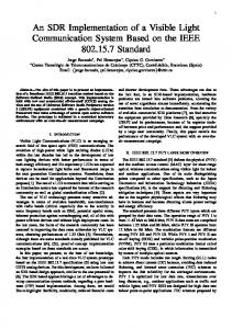
Fig. 7. Plot of % frequency shift versus % applied strain.
antenna. Thus, the measured scattering parameter contains the EM response of the tag in vertical polarization. The length of the antenna is increased along the vertical axis by applying the tensile force to the stretchable fabric. The first RCS measurement is done for the initial (“zero-strain”) antenna length, which is 135 cm. Then, the length is increased by small steps, applying a pulling force to the fabric. The RCS value of the tags has been measured for four different lengths, and the results are shown in Fig. 6. As one can see, the absolute value of RCS increases and the frequency peak decreases with the length of the antenna. This verifies that the applied strain on the antenna can be effectively sensed, monitoring the RCS as well. IV. DISCUSSION The fabric-based strain sensor studied in this letter has been interrogated using a dual-mode technique. Even though the sensor is implemented using a chipped RFID tag structure, it is validated also by a radar measurement technique, which is commonly utilized for the interrogation of chipless RFID tags, whereas getting the ID is still performed with the protocol-based reading technique. As it is shown in the results, the detection of the sensor by using radar measurement technique allows for obtaining similar curves as the read-range extraction technique. In both cases, the strain-due variation of antenna length as a physical parameter transforms into an RF parameter, such as the maximum read range or the maximum RCS values/corresponding frequencies shift. Moreover, the level of reflected power is another RF parameter that can be used to sense the strain for both techniques. The sensitivity in terms of frequency shift versus percentage of the applied strain is illustrated in Fig. 7. The slope of the best-fit curve gives a sensitivity of 0.66% frequency shift per 1% strain using radar technique. The sensitivity of 0.43% frequency shift per 1% strain is achieved using the read-range extraction
In this letter, we have presented a novel “dual-interrogation-mode” RFID strain sensor tag. This sensor combines both chipped and chipless RFID. The performance of the sensor has been measured using two different techniques, both of which allow for an accurate wireless strain sensing. The first technique utilizes the read range extraction that relies upon the detection of the threshold power. In the second technique, sensing is based on the measurement of RCS that is mostly used for identification of chipless tags. The combinations of the two interrogation techniques provide a passive RFID sensor having a large identification coding capacity for which the sensed parameter can be detected with no specific protocol. The simulation and measurement results prove that the chipped RFID-enabled strain sensor can be detected using chipless detection techniques as accurate as chipped technique. ACKNOWLEDGMENT The authors thank K. Koski and Dr. T. Björninen for their help. REFERENCES [1] A. Rida, L. Yang, and M. M. Tentzeris, RFID-Enabled Sensor Design and Applications, ser. Integrated Microsystems. Norwood, MA, USA: Artech House, 2010. [2] R. Bhattacharyya, C. Floerkemeier, S. Sarma, and D. Deavours, “RFID tag antenna based temperature sensing in the frequency domain,” in Proc. IEEE Int. Conf. RFID, 2011, pp. 70–77. [3] S. Manzari, C. Occhiuzzi, S. Nawale, A. Catini, C. Di Natale, and G. Marrocco, “Polymer-doped UHF RFID tag for wireless-sensing of humidity,” in Proc. IEEE Int. Conf. RFID, Orlando, FL, USA, Apr. 2012, pp. 124–129. [4] T. T. Thai, H. Aubert, P. Pons, G. R. DeJean, M. M. Tentzeris, and R. Plana, “Novel design of a highly sensitive RF strain transducer for passive and remote sensing in two dimensions,” IEEE Trans. Microw. Theory Tech., vol. 61, no. 3, pp. 1385–1396, Mar. 2013. [5] A. Vena, E. Moradi, K. Koski, A. A. Babar, L. Sydänheimo, L. Ukkonen, and M. M. Tentzeris, “Design and realization of stretchable sewn chipless RFID tags and sensors for wearable applications,” in Proc. IEEE Int. Conf. RFID, Orlando, FL, USA, Apr. 2013, pp. 176–183. [6] B. Zhang, Z. Zhou, K. Zhang, G. Yan, and Z. Xu, “Sensitive skin and the relative sensing system for real-time surface monitoring of crack in civil infrastructure,” J. Intell. Mater. Syst. Struct., pp. 17:907–17:917, 2006. [7] C. Occhiuzzi, C. Paggi, and G. Marrocco, “Passive RFID strain-sensor based on meander-line antennas,” IEEE Trans. Antennas Propag., vol. 59, no. 12, pp. 4836–4840, Dec. 2011. [8] E. Moradi, T. Björninen, L. Ukkonen, and Y. Rahmat-Samii, “Characterization of embroidered dipole-type RFID tag antennas,” in Proc. IEEE RFID-TA, 2012, pp. 248–253. [9] A. Vena, E. Moradi, K. Koski, A. A. Babar, L. Sydänheimo, L. Ukkonen, and M. M. Tentzeris, “An embroidered two-dimensional chipless strain sensor for wireless structural deformation monitoring,” IEEE Sensors J., vol. 13, no. 12, pp. 4627–4637, Dec. 2013. [10] P. V. Nikitin, K. V. Seshagiri Rao, S. F. Lam, V. Pillai, R. Martinez, and H. Heinrich, “Power reflection coefficient analysis for complex impedances in RFID tag design,” IEEE Trans. Microw. Theory Tech., vol. 53, no. 9, pp. 2721–2725, Sep. 2005. [11] W. Wiesbeck and D. Kähny, “Single reference, three target calibration and error correction for monostatic, polarimetric free space measurements,” Proc. IEEE, vol. 79, no. 10, pp. 1551–1558, Oct. 1991.