Such systems often require the timely execution of data-processing tasks that ... number of drawbacks that include a) the poor recovery in the case of lost or ...
Implementation of a MAC-layer Protocol (GIT-CSMA/CD) for Industrial LANs and its Experimental Performance V. D. Kapsalis(1), S. A. Koubias(2) and G. D. Papadopoulos(3) Applied Electronics Laboratory Dept. of Electrical & Computer Engineering UNIVERSITY OF PATRAS Rion - 26 500 Patras GREECE Abstract: This paper describes the pilot implementation of a local network by using a hybrid MACsublayer protocol (GIT-CSMA/CD) developed for hard real-time industrial Local Area Networks. This protocol outperforms standard CSMA/CD and token passing protocols as well as other hybrid protocols, in terms of mean and maximum packet delays versus throughput. Also, GIT-CSMA/CD offers bounded packet delay and a great degree of adaptation to the varying requirements imposed by the user applications. A seven-node pilot network was set up and its experimental performance evaluated. The implementation of the network node is based on the existing advanced microcontroller technology (INTEL 80C152 Communication Controller) and FPGA logic (XILINX XC3190). The measurements carried out in real-time on a 1 Mbps LAN yielding reproducible results. The comparison between the experimental and the simulation results showed excellent agreement. Keywords: real-time LANs, control networks, hard-real time MAC-layer protocols, hybrid protocols, CSMA/CD, Token passing, performance evaluation, network node implementation
I
INTRODUCTION
One of the recent applications of LANs is their use in distributed control systems. In the past decade, control systems based on embedded microprocessors have been used extensively in a number of systems and products: factory and home automation, building, as well as automobiles and security systems. However, due to the practical limits of the embedded control systems, such as low performance-cost ratios, and inherent problems, such as single points of (1)
Research Fellow, Ph.D.
(2)
Asst. Professor
(3)
Professor
failure, the demand arose for higher functionality, reliability and extensibility have been accelerated the development of distributed control systems based on local networks [1]. Such systems often require the timely execution of data-processing tasks that usually reside on different network nodes and communicate with one another to accomplish a common goal. End-to-end deadline guarantees require a communication network that supports the timely delivery of intertask messages [2]. MAC-sublayer protocols used in these networks aim to improve the throughput while ensuring that all time-constrained packets meet their deadlines (bounded packet delay). Systems in which the correctness of the whole operation depends not only on the logical result of the transactions, but also on the time at which the results are produced are called hard real-time systems, in contrast to soft real-time systems in which transactions are performed as fast as possible but are not strictly constrained to finish by a specific time [3]. The CSMA class of protocols has a long list of advantages: efficiency, low overhead, low-cost hardware, no network-wide synchronization requirements, and no tokens to lose. However, a number of drawbacks, like their non-deterministic nature and the difficulty in the introduction of priority mechanisms, made these protocols not well-suited for real-time applications [4]. An interesting variation of the CSMA algorithm is the predictive p-persistent algorithm (also referred to as CSMA/CA), that operates like a p-persistent CSMA, except that p is dynamically adjusted to match the expected traffic on the network [5]. This protocol, called LonTalk protocol, used by the MAC-sublayer of the LonWorks control network, reduces collisions dramatically and achieves sustained performance under heavy load conditions. Although optimal response times can be obtained by using an optional priority mechanism (by preallocating slots for different priority stations), the protocol does not guarantee bounded packet delays, because the priority mechanism does not eliminate the possibility of collisions; thus LonTalk is not well-suited for hard real-time applications [6,7]. Another attractive variation of the CSMA is the CSMA/CR, which uses a conflict resolution algorithm, and in the case of a collision allows the highest priority message to continue its transmission while the others yield [8]. A consequence of this algorithm, which is used by a control network called CAN [8] and a variation of the LonTalk protocol, is that the maximum allowable bit rates and the related connection lengths which are supported (62.5 Kbps over 1 km) are too short for networks in the process industry [9].
2
The most common protocols used in hard real-time applications belong to the token passing class [10-14]. All these protocols have a lower limit to the access delay due to the time spent waiting for the token, but guarantee an upper limit to the packet delivery time. However, a number of drawbacks that include a) the poor recovery in the case of lost or multiple tokens and after the failure of one or more stations and b) the need for reconfiguration of the bus whenever a station is added or removed, result in inaccessibility periods that may cause considerably increased packet delays [15]. The highest performance can be achieved by protocols that use hybrid access mechanisms [16,17]. Recently, the authors introduced a hybrid MAC-sublayer protocol, called Group Implicit Token-CSMA/CD (GIT-CSMA/CD), which effectively combines the advantages of CSMA/CD and token passing protocols, avoiding their major drawbacks. The details of the GIT-CSMA/CD protocol and its simulated performance evaluation can be found in [18,19,20]. In the next Section, a brief description of the hybrid protocol is presented; Section III describes analytically the implementation of the MAC and the Physical layers, while the next Section presents the implementation of a network node using the GIT-CSMA/CD protocol. A comparison between the experimental and the simulation results is presented in Section V and the conclusions are discussed in Section VI. II
OVERVIEW OF THE GIT-CSMA/CD PROTOCOL
The GIT-CSMA/CD protocol allows access on the channel using both contention and deterministic modes. It uses the concept of grouping the stations possessing the token, so that these stations are assigned the highest access priority over all the others. Each level of priority corresponds to different interframe space (IFS), that is the time between successive frames. The token passing mechanism is an implicit one, that corresponds to specific channel events rather than an explicit control packet, such as in the standard 802.4 token passing bus. The stations of the network (1,2,...,N) are connected in a bus topology and are organized in m groups (G1,G2,...,Gm) forming a logical ring. Each group contains k stations and the token is rotating among the groups under certain conditions (described below) after the channel state has changed from busy to idle. At the end of the current channel activity, the stations with the token (belonging to the GiT), continue to defer for a minimum interval Tt before initiating a transmission (if there are any pending packets) in token mode. Stations which are ready to transmit, but do not possess the token, wait for a time interval Tc (>Tt) and if none of the 3
stations with the token transmits, they will be able to gain access to the channel by using the 1persistent CSMA/CD protocol. The relationship between the CSMA/CD and token interframe spaces must guarantee that the token mode transmissions experience no interference by the CSMA/CD ones.
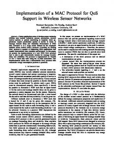
The implicit token passing among the stations occurs at the end of
channel activity periods when one of the following conditions has been fulfilled (Fig.1a-d): a) End of a valid transmission by (only) one station belonging to the group possessing the token (token mode transmission). b) End of a valid transmission by any station not possessing the token (CSMA/CD mode transmission). c) End of a collision among stations not possessing the token (CSMA/CD mode collision). d) End of the last token mode transmission (in Fig.1d it is assumed that k=2) during the deterministic collision resolution among the stations with the token. The procedures for the insertion and deletion of stations are completely distributed and do not require the transmission of any control packets. Thus, no procedures are needed for the initialization of the logical ring, as well as for any deletion of stations. The only procedure that must be followed by a station wishing to enter the ring is to be informed about the group currently possessing the token. It is achieved by having the station monitor the channel until a transmission is initiated at a time instant lying between Tt and Tt+2τ after the end of the previous transmission, where 2τ is the round-trip propagation delay. This event can trigger a promiscuous mode [21] for the new station's controller (receiving packets irrespective of their destination addresses). The group currently possessing the token will be determined by the source address of the received packet (each station knows the addresses of the stations forming a group). The new station will calculate the value of the busy-to-idle channel state changes before the new station is in possession of the token (corresponding to the current token position), t, as:
(
)
t = mod m GiT − Gn {S j } − 1
(1)
where GiT is the group identity of the station which transmitted and Gn{Sj} is the identity of the new station's group. After the determination of t, the network controller will return to normal mode (receiving a packet only if the destination address of the packet coincides with its individual address) and it will decrease the value of t by one, when one of the above conditions is detected; the station with t=0 possesses the token. If, during the insertion of a new station, a predefined number of busy-to-idle channel state changes take place without any transmission in token mode, the new station obtains the token by setting t=0. 4
The algorithm which controls the retransmission of collided packets in CSMA/CD mode is a modification of the Binary Exponential Backoff (BEB) method and guarantees (in conjunction with the token mode operation) an upper delay bound for the retransmission of all the collided packets. Analytically, if a collision among the stations without the token is detected, all stations involved terminate their transmissions, send jam signals and schedule retransmissions after a random number of slots (backoff interval); these stations get in the backoff state. The number of slot times, Tcs, to delay before the nth retransmission attempt is chosen as a uniformly distributed random integer r in the range: 0 ≤ r < 2 ( n −bν )
(2)
where v is an integer used for the calculation of the upper limit of the backoff interval (2v-1) and b=(n-1)/ν. In the case that one station gets the token while it is still in the backoff state, it truncates the backoff interval and transmits its packet in token mode. The maximum delay before a successful packet transmission, Tfc, due to the backoff algorithm is given by: c ν T fc = m(Tc + Pc + Ps ) + Tcs l ∑ ( 2 i − 1) + ∑ ( 2 i − 1) + Tt + Ps i =1 i =1
[(
)
]
= m(Tc + Pc + Ps ) + Tcs l 2( 2 ν − 1) − ν + 2( 2 c − 1) − c + Tt + Ps
(3)
where, l=m/ν, c=m-lν, Pc is the collision packet length and Ps is the maximum packet length. This delay stands for the case in which the packet arrives at the top of the station’s queue just after this station has lost the token. Also, a collision takes place each time the station initiates a transmission, followed by the maximum allowable (by the backoff algorithm) time interval, until the station gets the token and transmits its packet in token mode. A different procedure is followed if a collision among the stations of the group possessing the token is detected; a deterministic collision resolution takes place, allowing any station of the group to transmit its previously collided packet at its preassigned slot without experiencing any interference. At any time, each of the stations belonging to GiT, owns a distinct slot of duration at least equal to the maximum round-trip propagation delay (Tds=2τ). Each station defers for a number of slots equal to its relative position inside the group (from 1 to k) before initiating a retransmission. If a station belonging to GiT detects no transmission on the channel (by the stations of its group that own a preceding slot) upon its scheduled transmission point, then it transmits. Otherwise, if any packet transmission is detected, the station stops counting (slots) and waits for the end of carrier, where it continues the above procedure (deferring for the rest of slots) until its own preassigned slot, where it transmits. During the deterministic collision 5
resolution among the stations of GiT, no transmission is allowed to be initiated by any station not having the token. According to reported simulation results [18,19,20], the highest performance (assuming symmetric traffic) in terms of mean delay - throughput is achieved if each group contains two stations (k=2); in terms of limiting the maximum delay the optimum value is k=1 (no grouping). The maximum packet, due to the token mode operation delay (for a packet arriving at the top of the station’s queue) is given by [18]:
[
]
T ft = ( m − 1) ( k + 1) Tt + kPs + Pc + [m( k − 1) + 1]( Ps + Tt ),
k≥2
(4)
If the stations are not grouped (k=1), the maximum packet delay is equal to: T ft = N ( Ps + Tt ),
k=1
(5)
The maximum packet delay guaranteed by the hybrid protocol, is given by:
(
T fm = max T fc , T ft
)
(6)
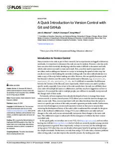
As the load increases the GIT-CSMA/CD gradually becomes a collision-free (individual token) protocol that results in a very high throughput. The transition from group token to individual token mode, where only one station possesses the token, takes place each time a collision occurs among the stations of the group currently possessing the token. During each operation cycle after this collision, the token belongs to only one station (among k stations) of the particular group; these operation cycles are called individual cycles. The transition back to the group token mode takes place only if at most one among the k stations belonging to the particular group transmits in token mode at its individual cycle. Fig.2 illustrates the mechanism for the transition between the group and individual token mode of operation for four successive operation cycles (M - M+3). Initially, the stations S5, S6 (k=2), which belong to the same group, G3T, operate in group token mode until a collision between them (in token mode) takes place; the deterministic collision resolution period which follows allows them to transmit their packets in the predetermined slots without any interference (M cycle). The next cycle for the G3T is in individual token mode; the token belongs only to S5, which transmits in token mode without any interference by S6, which transmits in CSMA/CD mode after the end of the previous transmission (M+1 cycle). During the next operation cycle (M+2), the individual token belongs to S6, which is inactive and thus a station with a ready packet transmits (S1) in CSMA/CD mode; this event triggers a transition back to the group token mode for the G3T. At the fourth cycle (M+3), the stations of the G3T operate in group token mode but only S5 is active and thus it transmits its packet without any interference. 6
The combination of CSMA/CD and token mode (group and individual) operation offers a great degree of adaptation to a wide range of loads and a number of different application requirements. Furthermore, the problem of lost tokens is avoided because of the implicit token passing mechanism. Thus, no bandwidth is wasted and the inaccessibility periods of the classical token passing protocols which may cause considerably increased packet delays are avoided [15]. The maximum achievable throughput (C) for the GIT-CSMA/CD is given by:
C=
III
Ps Ps + (Tt + τ )
(7)
IMPLEMENTATION OF THE GIT-CSMA/CD PROTOCOL
The Physical and the MAC layers of the new hybrid protocol GIT-CSMA/CD for k=2 stations/group (optimum value in terms of mean delay-throughput, [18,19,20]) were implemented and a seven-station network was setup for experimental measurements. The implementation of the new hybrid protocol was based partially on the capabilities and the features of INTEL Universal Communication Controller (80C152) [21]. The inherent capabilities of 80C152 include CSMA/CD 1-persistent operation, Binary Exponential Backoff mechanism, address recognition and control of the interframe space. The additional operations necessitated by the implicit token rotation, synchronization of each network station, error handling rules, insertion and deletion of stations in the logical ring are controlled by a number of units which have been implemented in a FPGA (XILINX 3190) [22]. Table 1 illustrates the machines (and units) implemented by each module. A brief description of the operations performed by each machine and unit follows. • Interface Machine (IFM): It is the interface between LLC-MAC and NMT-MAC layers. It handles the incoming primitives (requests) from LLC and NMT layers for packet transmissions and is responsible for the primitives (indications and confirmations) to these layers. • Receive Machine (RxM): This machine receives the incoming bits from the Physical layer, transforms them into frames, checks for FCS errors and passes each frame to the IFM only if its address field coincides with the individual or group address(es) of the station. • Transmit Machine (TxM): This machine receives data consisting of Destination Address (DA), Source Address (SA) and Data Fields, transforms them into frames by adding Preamble and FCS Fields and passes them to the Physical layer for transmission. If a 7
collision is detected, the TxM suspends its transmission and sends a jamming signal to inform all the network stations about this collision. Table 1 Machines (and units) implemented by each module
LAYERS
Phy_Card
MEDIUM ACCESS
80C152
XC 3190
IFM
CTU
TxM
TPU
RxM
--
AU
CONTROL
SU
LIU COLLISION DETECTION PHYSICAL
RECEIVER
ENC/DEC
DRIVER
CLOCK
--
EXTRACTION
• Access Control Machine (ACM): The major part of the MAC procedures is implemented by the ACM that consists of a number of units: a) Channel Tracing Unit (CTU): This unit watches the channel activity, notifies the TPU
about the time instant of token rotation and the mode of token operation (group or individual) and detects errors caused by multiple tokens and loss of synchronization. b) Token Passing Unit (TPU): It is responsible for the control of token passing procedure
among the network stations, notification about the time instant of token possession to CTU and about the transmission mode (CSMA/CD or token mode) to AU. c) Synchronization Unit (SU): It is responsible for the synchronization of CTU and TPU
of the ACM each time the station starts operating. d) Logical Insertion Unit (LIU): It controls the procedure for the insertion of a station to
the logical ring of token rotation, by modifying the receive mode of the RxM in order to receive the first detected token mode transmission (initiated by the current token possessor) and thus calculating the current token position, t (Eqn.1). e) Access Unit (AU): This unit controls the transmission procedure, defers the packet
transmission whenever the channel is busy and schedules a retransmission after the detection of a collision and the expiration of the backoff interval. 8
A.
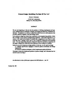
Interconnection of the Machines and Units of the MAC Layer
Fig.3 illustrates the interconnection between the machines and the units of the MAC layer that communicate by means of the following variables and signals: channel_busy: A Boolean variable that is equal to "1" when the channel is busy and equal to
"0" when the channel is idle. syncc: It is a Boolean type variable, used by CTU and TPU as a time reference point, allowing
them to accurately determine the mode of the next transmission. If syncc sets, it declares that the next transmission will take place in CSMA/CD mode. synct: It is used as the previous variable, except that the synct declares the end of a token mode
transmission and denotes: a) the beginning of the measurement of the idle channel state duration, in order for the CTU to determine the mode of the next transmission and b) the time instant of the token transfer to the next group. token_rotation: A Boolean variable which is used by the TPU in order to control the rotation
of the implicit token among the group of stations. Analytically, the TPU decreases the Token Rotation Counter (TRC) by one (this counter is described below), when a transition (from 1-to0) of token_rotation is detected. token_mode: It is a Boolean variable which corresponds to the current token mode (group or
individual) for the particular station. frame_ready: This variable notifies the TPU (and AU) about the existence of a ready frame
waiting for transmission. insertion_enable: A Boolean variable which is equal to "1" until the determination of the
current token position; the insertion_enable is cleared by the TPU, when the current token position (determined by the LIU) is written to the TRC. insertion_control: This variable controls the time instant that LIU will start (finish) the
procedure for the determination of the current token position. receive_mode: It is a variable that programs the RxM at the promiscuous mode (receiving the
frame irrespective of its destination address). The source address of this frame corresponds to the current token possessor. Thus, the value of the current token position is determined (Eqn.1) and consequently written to the Token Position Register (TPR) of the TPU (described below). After the end of the insertion procedure, the LIU reprograms the RxM to its previous receive mode.
9
current_token_position: The value of this variable is written by the LIU and corresponds to
the current token position relative to the position of the particular station. token_possession: This variable declares the token possession (irrespectively of the value of
the frame_ready) and is used by the CTU in order to properly interpret the conditions for the transition between the two token modes of operation (group and individual). token_flag: It is a Boolean variable which is being set by the TPU and declares that the
particular station is the current token (group or individual) possessor. Note that this variable is not set if frame_ready=0. received_frame: A block of data containing the received frame. Rx_frame_status: A variable which corresponds to the status of the received frame (reception
completed, reception error). In the case of an error, the value of the Rx_frame_status corresponds to this specific error. transmitted_frame: A block of data containing the frame to be transmitted. Tx_frame_status: A variable which corresponds to the status of the transmitted frame. send_frame: A variable that controls the transmission of a ready frame; when set the
transmission starts. collision: A Boolean variable which is set after a collision detection. B.
System Interface
The microcontroller 80C152 considers the FPGA as a peripheral device and communicates with it by means of an Address/Data bus, interrupt and control/status signals. The system interface performs control/status transfers, parameter transfers and interrupts. Fig.4 is a block diagram illustrating the interconnection between the 80C152 and XC3190 and the registers of each unit which are accessed by the microcontroller and the FPGA. There are two kinds of transfers over the bus: control/status and parameter transfers. The control and parameter transfers are always initiated and performed by the 80C152, which controls the FPGA by writing into the Control and Data Registers. The microcontroller writes a command by selecting the address of the Control Register (CR), putting the command onto the data bus and activating the WR signal. The command byte is latched into the CR and the FPGA decodes the command and performs the required operation. The notification of the microcontroller about the status of several operations performed by the units which have been implemented in the FPGA (SU, CTU and TPU) takes place by means of an interrupt signal and a Status Register (SR). 10
The format of the Control Register (CR) is shown below: Control Register (CR):
7
6
5
4
3
2
1
AL
--
--
--
--
OA
FR
0 RESET
RESET: The RESET bit, if set, causes all the circuits of the FPGA to be reset. FR: This bit (frame_ready) notifies the TPU and the AU about the existence of a ready frame
waiting for transmission. OA: The value of the OA (odd_address) bit corresponds to the LSB of the station's individual
address and is written only at the initialization phase. Each group contains two stations (k=2): one with even address and one with odd address. During individual token mode operation, at which the token belongs to only one station of the group, each station possesses the token at different operation cycles. The OA bit is used by the TPU during individual token mode cycles in order to determine the time instant of the individual token reception. AL: The AL (Address_Latched) is a bit which must be set before the value of the OA bit can
be written to the CR. The format of the Status Register (SR) is shown below: Status Register (SR):
7
6
5
SYNCH
INSERTOFF
4
SYNCE MULTE
3
2
1
INSERTON
--
INDMOD
0 TF
TF: This bit (token_flag) is set by the TPU in order to notify the AU about the possession of
the token (group or individual token). INDMOD: The value of the INDMOD bit (individual_mode), in conjunction with the value
of the TF bit, corresponds to the current token mode (group or individual token), as illustrated in Table 2: Table 2 Determination of the token mode
TF
INDMOD
TOKEN MODE
1
0
GROUP TOKEN
1
1
INDIVIDUAL TOKEN
INSERTON: This bit (insertion_on) is set by the CTU at the logical insertion phase of the
station and notifies the LIU about the initiation of a token mode transmission. The LIU 11
responds by programming the RxM in promiscuous mode (see the above description of the receive_mode variable). MULTE: It is a bit (multiple_token_error) which is set by the CTU and informs the Network
Management (NMT) layer about errors due to the existence of multiple tokens. In this case, the initialization procedure is performed again. SYNCE: This bit (set by the CTU) informs the NMT layer about a synchronization error
(sync_error). INSERTOFF: If the token mode transmission, which caused the INSERTON interrupt by
the CTU experiences a collision, then the INSERTOFF bit is set, informing the LIU to reprogram the RxM in the normal receive mode until the next token mode transmission is detected. SYNCH: The end of a successful synchronization operation by the SU (syncc=1 or synct=1)
sets this bit and causes the total number of groups to be written at the Token Rotation Register (TRR) by the 80C152. The Status Register must be read if the interrupt signal is set. Reading the Status Register will clear the interrupt and the corresponding bit which caused the particular interrupt. C.
Functional Description of the FPGA Units
The operation of the SU and CTU is based on the detection of specific channel events which can be properly interpreted based on their time duration. These events are the following: • token mode collision • CSMA/CD mode collision • token mode transmission • CSMA/CD mode transmission The duration of any busy/idle channel periods is determined by a Busy/Idle timer (Fig.4), which starts counting whenever a busy-to-idle or an idle-to-busy transition takes place. Analytically, each transmission which is being initiated at a time interval shorter than Tt+2ô after the end of the previous transmission is interpreted as a token mode transmission, otherwise it is interpreted as a CSMA/CD transmission; this time interval value is contained at the Channel Idle Register (CIR). A packet is interpreted as a collision if its duration is shorter than a predetermined value contained in the Channel Busy Register (CBR). The count
12
values for the idle and busy periods are loaded at the CIR and the CBR respectively, during the initialization phase of each station. The SU is responsible for the synchronization of both CTU and TPU. The time instants of token transitions between successive groups are determined by specific channel events (illustrated in Fig.1). The synchronization signals (syncc and synct) provided by the SU to both CTU and TPU ensure that the interpretation of these events is correct. The basic operations of the CTU are: a) watch and interpret the channel events by using the channel_busy, syncc and synct signals, b) control the procedure for the token rotation by the token_rotation signal, c) notify the TPU (and AU) about the token mode (group or individual) by the token_mode signal, d) control the insertion of the station in the logical ring by the insertion_control signal and e) detect errors due to multiple tokens and synchronization loss and inform the NMT layer about them (by asserting the MULTE and SYNCE bits of the SR, respectively). The TPU is responsible for the implicit token rotation (Figs.1,4). The current token position is determined by the contents of the Token Rotation Counter (TRC) which decreases its value by one when a transition (from 1-to-0) of token_rotation is detected. When TRC expires, the token_possession variable sets and a new counting initiates; the autoreload value for TRC is equal to the number of groups (m) and contained in the Token Rotation Register (TRR). However, at the end of the insertion phase (the current token possessor has been determined), the TRC starts its counting from a value equal to the current_token_position (t) which is calculated by the Logical Insertion Unit (LIU); this value is loaded to the Token Position Register (TPR) by LIU. The value contained in the TPR is used only once, during the startup of the station. D.
Implementation of the priority mechanism
The assignment of higher access priority to the stations belonging to the group currently possessing the token over all others is achieved by a modification of the interframe space; the description of the analytic transmission procedure for a station possessing the token follows: • A request for a frame transmission by the upper layers sets the FR bit of the Control Register (CR). • If, the station possesses the token while FR=1, the TF bit of the Status Register (SR) is set and an interrupt signal asserts (from the TPU); the interrupt takes place at the end of the current channel activity. 13
• The token mode (group or individual) is determined by the value of the INDMOD bit of SR. • The AU: a) truncates the backoff interval, if the frame has collided in CSMA/CD mode before the token possession, and b) decreases the interframe space from Tc to Tt . • If INDMOD=0 (group token mode), the token belongs to both stations of the group. Thus, if both stations have frames waiting for transmission, a token mode collision will occur when they start transmitting. In order to avoid successive collisions between these stations, each of them is programmed to retransmit at a different slot. This is achieved by examining the OA (Odd_Address) bit which has been written at the initialization phase; the station with OA=0 transmits first, followed by a transmission of the second station belonging to the group. • If INDMOD=1 (individual token mode), the token belongs to only one station of the group and the token mode transmission starts after the expiration of Tt, without experiencing any interference. IV
IMPLEMENTATION OF A NETWORK NODE BASED ON GIT-CSMA/CD
A hard real-time network supporting different level of priorities has been implemented by combining the processing capabilities of INTEL 80C152 microcontroller and XILINX XC3190 FPGA; transmission rates are up to 2 Mbps. Each industrial control node of the network includes (in addition to the power supply and the digital/analog I/O cards) the Main Card and the Physical-layer Card (Phy_Card) (Table 1). A.
The Main Card
Fig.5 illustrates the layout of the Main Card which includes the following components: •
microcontroller: INTEL 80C152
•
FPGA: XILINX XC 3190
•
serial memory for the programming of XC 3190: XC 1765
•
external code memory (EPROM): 27C256
•
external code/data memory (SRAM): 62C256
•
RS-232 driver: DS14C88
•
RS-232 receiver: DS14C89
•
connector for the I/O cards 14
•
DB9 connector: RS-232 interface
•
DB9 connector: network (GIT-CSMA/CD) interface
•
SIP connector: Physical-layer Card (Phy_Card) interface
The 80C152 can access two separate address spaces (up to 64K bytes of each region) of memory: Program and Data Memory. The demultiplexing of the address/data bus and the decoding of the addresses, in order to select the I/O cards, is included in the functions performed by the FPGA (Fig.4). B.
The Physical-layer Card (Phy_Card)
The Physical layer is responsible for the physical connection of the stations to the medium, encoding/decoding of data, clock extraction and collision detection. As illustrated in Table 1, the encoding/decoding of data (in Manchester code) and the clock extraction are performed by the microcontroller. Furthermore, the microcontroller is able to detect collisions by detecting Manchester waveform violations at its data input. Three kinds of waveform violations are detected: a missing 0-to-1 transition where one was expected, a 1-to-0 transition where none was expected, and a waveform that stays low (or high) for too short a time [21]. The differential line driver and receiver (RS-485) and an analog circuit which detects collisions and informs the microcontroller by properly violating the Manchester code, are implemented in the Physicallayer Card (Phy_Card) which is connected to the Main Card through a SIP connector (Fig.5). V
EXPERIMENTAL RESULTS
A.
Experimental Setup
This Section describes the experimental procedure for the measurement of the performance of the GIT-CSMA/CD with k=2 stations/group. A seven-station network was set up for performance evaluation measurements in different traffic values. Five of these stations are used for the generation of the network load (Load Generators, LGS); the sixth station measures the delay for each packet transmission (Delay Measurement Station, DMS). The throughput value for each measurement is calculated by the seventh station (Throughput Measurement Station, TMS). The traffic volume was varied by changing the average packet interarrival time (IT). The packet interarrival times, corresponding to specific predefined scenarios, where generated by the PC and then transferred and stored in a table of 8192 entries (corresponding to 4096 interarrival times) on the Data memory of the Load Generator Stations (LGS). This was 15
achieved through the RS-232 interface by means of several network management services implemented to control the functions of the Main Card. A station generates a packet by fetching an IT from the external memory, loading it into the timer 0 of the 80C152 and starting the timer. When the timer count reaches the preset time, the microcontroller is interrupted and a packet is generated. The indicator of the table containing the ITs increases by two bytes and if it is exhausted (all the table entries have been used) it is reused from the beginning of the table. If there isn't any other packet waiting for transmission (queue empty), then the transmission procedure starts; otherwise the packet enters the station's queue and the queue indicator increases by one. The packet transmission is initiated whenever the queue contains at least one packet. This procedure operates independently and after a successful transmission it decreases the queue indicator by one. The operation of the Delay Measurement Station (DMS) is similar to that of the LGS except for these differences: a) When a packet is generated, timer 1 is enabled and not disabled until the packet is successfully transmitted; the value of the timer 1 is stored at the table containing the packet delays. The indicator of this table increases by two; the delay measurement procedure stops if the delay table is exhausted. b) After the successful transmission of a packet timer 0 is loaded with the next IT and starts counting the interarrival time for the generation of a new packet. The seventh station operates in promiscuous mode and receives all the valid packets transmitted through the network in order to calculate throughput values. Synchronization of the experimental measurements is achieved by initiating the operation of the TMS at the time instant that the DMS transmits its first packet. For each throughput value, the packet delays which have been written to the delay table of the DMS are transferred (uploaded) to the PC. A program, running at the PC, calculates the mean and the maximum packet delay for each throughput value. Finally, the mean and maximum packet delays and the throughput for each measurement correspond to two points of the mean packet delay-throughput and the maximum packet delay-throughput characteristics, respectively. The same procedure is repeated for the whole range of offered loads up through the maximum throughput value (capacity) achieved by the protocol. B.
Results
16
In this section, the performance results of GIT-CSMA/CD (k=2 stations/group), obtained both experimentally and by simulation are presented. The experimental configuration and the parameter values are as follows (based on the features and capabilities of 80C152): • bit rate: 1 Mbps • number of stations: N=6 (the seventh station is not taken into account because it is in receive mode), stations/group: k=2, number of groups: m=3 • propagation delay: ô=1, packet length: Ps=500 and 200, jam: 16, preamble: 16, collision packet length: Pc ≥ jam+preamble = 32 (in bits) • minimum time between successive transmissions (interframe space): Tt=20 bits (corresponds to the token mode transmissions) • time between successive CSMA/CD transmissions: Tc > 2( Tt + 2ô) = 50 bits • slot for the backoff algorithm: Tcs ≥ Tc + 2ô=56 bits, upper limit of the backoff interval: ν=3. The traffic characteristics of any application can be modeled by a limited number of predefined traffic classes; each model used to describe a specific application is called a scenario. The simulations and measurements performed provide a general analysis of the bus access mechanisms in certain typical situations modeled by the following scenarios: equalpriority, station-based priority and message-based priority scenarios. Equal-priority scenario:
In order to verify the validity of the experiment, the first
measurement was taken under the assumption that all the stations generate equal-priority messages. Analytically, all the stations operate under the GIT-CSMA/CD (k=2) and generate packets according to the Poisson process (exponential interarrival times). One queue per station is assumed with queue length equal to 50 packets. Fig.6 shows that the mean packet delay-throughput characteristics of the experimental results and the simulation model are in excellent agreement for the whole range of offered load. Station-based priority scenario: An inherent feature of the new MAC protocol is its feasibility
to interconnect high-priority stations (Nhp), operating under GIT-CSMA/CD, with low-priority stations (Nlp), operating under CSMA/CD 1-persistent. Fig.7 illustrates mean packet delay versus throughput for high- and low-priority stations under the assumption that two stations operate under GIT-CSMA/CD (Nhp=2) and four stations use CSMA/CD 1-persistent (Nlp=4); the packet generation for both types of stations obeys the Poisson process. Obviously, highpriority stations experience a significantly lower mean packet delay than their low-priority 17
counterparts. Fig.8a refers to mean packet delay versus the high-priority offered load (assuming Nhp=2 and Nlp=4) for different low-priority load values (ρlp=0.2, 0.4 and 0.6) and in Fig.8b the mean packet delay for the low-priority stations is represented for fixed highpriority load values (ρhp=0.2, 0.4 and 0.6). Two considerations can be derived from Fig.8: a) the mean packet delay for the high-priority stations is practically independent of the lowpriority offered load (Fig.8a) and b) the low-priority packet delays are significantly increased during peaks of high-priority traffic (Fig.8b). The measurement and simulation results under the station-based priority scenario verify that the performance of the high-priority stations (in terms of mean packet delay) is not affected by the simultaneous operation of both types of stations. This feature results in significant cost reduction of the whole network, because the stations without time constraints can operate under the simple 1-persistent CSMA/CD. Message-based priority scenario: This scenario was imposed by analyzing the data traffic
produced in a number of typical distributed industrial applications, concerning the interconnection of sensors, actuators and control devices (fieldbus networks); this traffic can be divided into three main classes [5,6], [14], [23]: • Periodic (or cyclic) time-critical traffic, generated by the exchange of measurement and control data between sensors, actuators and controllers. • Aperiodic (or event-driven) time-critical traffic, consisted of alarms and/or urgent control signals, which are triggered by specific events (e.g. change of a variable state) and • Aperiodic time-available traffic, generated by the exchange of network management messages (e.g. application data downloading). GIT-CSMA/CD guarantees at least one packet transmission per station in a time interval equal to Tfm (Eqn. 6). If we denote the high-priority queue length as qhp, then the bounded packet delay is equal to qhp* Tfm (qhp ≥1). For the sake of simplicity the results presented in this section refer to a high-priority queue length of one packet (qhp=1). However, the conclusions drawn can be easily extended to a more complicated situation with qhp>1. Thus, the simulation model for the high-priority traffic (ρhp) consists of: • A periodic (cyclic) portion which corresponds to a generation of one packet per station in time intervals of Tp = 2*Tfm. Equivalently (in terms of average values) the generation of each packet can take place in time intervals equal to Tfm with probability pc = 0.5. Thus, the average load that corresponds to the periodic (cyclic) traffic (ρc) is:
18
ρc =
pc NPs Tp
(8)
By substituting the values of the above parameters in Eqn.8 (pc = 0.5, N=6, Ps= 200, Tp=Tfm) and Tfm= 9.32*Ps (Eqns.3, 4, 6 for m=3, k=2, ν=3, Tt =20, Tc =50, Tcs =56, Pc = 32), the average cyclic load is ρc=0.32. • An aperiodic time-critical portion that generates packets according to a random distribution in time intervals equal to Tfm. Equivalently, taking into account the restriction imposed by the one-packet queue length (at most one high-priority packet in a time interval equal to Tfm), each packet is generated in time intervals equal to Tfm with a uniformly distributed probability pa (0≤ pa≤1- pc). The average load that corresponds to the aperiodic traffic (ρa) is:
ρa =
pa NPs T fm
(9)
Assuming the same parameter values as above (Ps for all classes of traffic is 200 bits) and 0≤ pa≤ 0.5, the average aperiodic load is ρa=0.16; thus the total high priority average load is ρhp= (ρc+ρa )=0.48. The low-priority aperiodic time-available traffic (ρlp) is generated according to a Poisson process. Fig.9 illustrates the mean and maximum packet delay versus throughput for highand low-priority type packets. As illustrated in the figure, the maximum packet delay both for the experimental measurements and the corresponding simulation results match closely with the theoretical maximum value guaranteed by the protocol (Tfm=9.32*Ps). Fig.10 illustrates the distribution of the high-priority and low-priority packet delays with throughput (S) as a parameter (S=0.63 and 0.83); the average high-priority offered load is equal to ρhp=0.48 for both throughput values. It is shown that the delays of the high-priority packets obey a bounded distribution for both throughput values, in contrast to the delays of the low-priority packets which increase unboundedly as throughput gets higher. These figures verify that, under this scenario (imposed by typical distributed industrial applications), the hybrid protocol guarantees an upper bounded delay for the high-priority traffic. VI
CONCLUSIONS
In this paper, the implementation of the hybrid GIT-CSMA/CD (for k=2 stations/group) protocol is described. In order to measure the experimental performance, a number of test 19
programs has been developed; the experimental results showed an excellent agreement with the simulation results in a number of typical situations modeled by the following scenarios: equal-priority, station-based priority and message-based priority scenarios. The most important advantages of the GIT-CSMA/CD protocol include the following: • Channel access by both CSMA/CD and token mode techniques. • Adaptation to a wide range of loads and application requirements by varying the number of stations/group. • Elimination of the inaccessibility periods due to the implicit token passing. • Completely distributed algorithms for the insertion/deletion of stations to the network. • Feasibility of interconnection between high- and low-priority stations at the same network without any performance degradation for the high-priority ones. • Introduction of message-based priorities. • Bounded packet delays for the high-priority traffic (suitable for hard real-time applications). It can be concluded that the features of the GIT-CSMA/CD MAC-sublayer protocol make it suitable for high-performance distributed control networks which require robustness. The simulation results and the experimental measurements which carried out in a pilot network, concerning three predefined scenarios, verify that the new hybrid protocol is an attractive solution for a number of different application requirements with hard-real time properties. REFERENCES [1]
S. Raji, "Smart networks for control", IEEE Spectrum, vol. 31, No 6, pp.49-55, June 1994.
[2]
N. Malcom and W. Zhao, "The Timed-Token Protocol for Real-Time Communications, "IEEE Computer, pp.35-41, Jan. 1994.
[3]
J.R. Pimentel, "Integrated Manufacturing Network Architectures", in Proc. IEEE Infocom'89, pp.1128-1129, 1989.
[4]
L. Ciminiera, C. Demartini, and A. Valenzano, "Industrial IEEE 802.3 Networks with Short Delivery Time for Urgent Messages", IEEE Trans. Indus. Electron., vol.35, no 1, pp.18-25, Feb. 1988.
[5]
LonTalk Protocol, Echelon Corp., April 1993.
[6]
LonTalk Response Time Measurements, Echelon Corp., March 1992.
[7]
J.R Jordan, "Transducer interconnection with a standard fieldbus", Strain, pp.125-133, Nov. 1993.
[8]
"CAN Specification" Version 2.0, Robert Bosch GmbH, 1992, ISO/TC22/SC3/WGI document.
20
[9]
R. Mores and M.J. Morse, "Fibre-based local area network with priority access", IEE Proc. Commun., vol.141, no.3, pp.203-208, June 1994.
[10] ANSI/IEEE, Std. 802.4, "Token-Passing Bus Access Method", 1985. [11] Manufacturing Automation Protocol, Version 2.1, GM Tech. Center, Warren, MI, Mar. 1985. [12] IEC: Specifications for highway interface-logical (pt.2), Specifications for high way unit protocol (pt.3), SC65 WG6, 1984. [13] SAE Draft (Proposed) Standard: "Linear token passing multiplex data bus", SAE-STD-AE9BL, Revision H, The Society for Automotive Engineering (SAE), October 1986. [14] A. Di Stefano and O. Mirabella, “Evaluating the Field Bus Data Link Layer by a Petri Net-Based Simulation”, IEEE Trans Indus. Electron., vol.38, no 4, pp.288-297, Aug. 91. [15] J. Rufino, P. Verissimo, "A study on the Inaccessibility Characteristics of ISO 8802/4 Token-Bus LANs", in Proc. INFOCOM ‘92, pp. 958-967, 1992. [16] P. Gopal and J. Wong, "Analysis of a Hybrid Token- CSMA/CD Protocol for Bus Networks", Computer Networks and ISDN Systems 9, pp. 131-141, 1985. [17] P. Gburzynski and P. Rudnicki, "A Better-than-Token Protocol with Bounded Packet Delay Time for Ethernet-type LAN's", in Proc. Symposium on the Simulation of Computer Networks, pp. 110117, Aug. 1987. [18] V.D. Kapsalis, S.A. Koubias and H.C. Haralabidis, "New hybrid MAC-layer protocol for real-time bus networks", IEE Proc. Commun., vol.141, no.5, pp. 325-333, Oct. 1994. [19] V.D. Kapsalis, S.A. Koubias and G.D. Papadopoulos, "Performance Evaluation of a Hybrid MAC-layer Protocol for Hard Real-Time Industrial Networks", in Proc. IEEE Int. Symposium on Indus. Electronics, pp.148-152, July 1995. [20] Koubias, S.A, G. D. Papadopoulos, "Modern Fieldbus communication architectures for real-time industrial applications", Computers in Industry, Elsevier Science B.V., Vol.26, pp. 243-252, 1995. [21] INTEL, Embedded Microcontrollers and Processors, Volume I, 1992. [22] XILINX, "User Guide and Tutorials", 1991. [23] S. Cavalieri, A. Di Stefano and O. Mirabella, “Optimization of Acyclic Bandwidth Allocation Exploiting the Priority Mechanism in the Fieldbus Data Link Layer”, IEEE Trans Indus. Electron., vol.40, no 3, pp.297-306, June 1993.
21
t Tt
(a)
c Tc
Tc
(b)
(c)
t
t Tt
Tt
Tt
(d) : time instants of token rotation
t
: token mode transmission
c
: CSMA/CD mode transmission
: collision
Fig.1 Implicit token passing among the groups of stations
22
G3T M 5
6
Tt
t
S5
t Tt
Tt
G3 T M+1
t 6
5
S6
G4 T S5
t
Tt
S6
Tc G3T
M+2
S1
c Tc
1
G3T M+3
t 5
G4T S5 Tc
Tt 4
x
9
: packet arrival at station x
t
Sx
: token mode transmission by station x
c
Sx
: CSMA/CD mode transmission by station x : collision
Fig.2 Mechanism for the transition between group and individual token mode of operation
23
LLC MAC
token_mode
token_mode
insertion_control
token_rotation,
token_flag
frame_ready
Access Unit (AU)
Transmit Machine (TxM)
Logical Insertion Unit (LIU) receive_mode
collision
channel_busy
send_frame
received_frame
Token Passing Unit (TPU)
insertion_enable, token_possession
Rx_frame_status
syncc, synct
Synchronization Unit (SU)
current_token_position
syncc, synct
Channel Tracing Unit (CTU) Tx_frame_status
transmitted_frame
Access Control Machine (ACM )
frame_ready
Interface Machine (IFM)
Receive Machine (RxM)
PHYSICAL Collision Detection
Fig.3 Interconnection between machines and units of the MAC layer
24
ADO-AD7
/RD
/WR ALE
ALE A0A7
ADO-AD7
25 BUSY/IDLE TIMER
A8-A15 3 AD0AD7 TIMER CONTROL LOGIC
BUSY/IDLE TIMER
CHANNEL BUSY REGISTER (CBR)
TPU LOGIC
TOKEN ROTATION COUNTER (TRC)
TOKEN POSITION REGISTER (TPR)
TOKEN ROTATION REGISTER (TRR)
CONTROL SIGNALS AD0AD7
CHANNEL IDLE REGISTER (CIR)
ADDRESS DECODING
A8-A15
STATUS REGISTER (SR)
ADO-AD7 STATUS SIGNALS
CONTROL REGISTER (CR)
INT
ADDRESS-DATA DEMULTIPLEXING
AD0-AD7
80C152 XC 3190
INT INTERRUPT HANDLING
TPU SU
SU LOGIC
CTU
CTU LOGIC
/WR /RD
Fig.4 Interface between the microcontroller and the FPGA
GIT-CSMA/CD Interface
DB9
26 62C256
62C256 OR 27C256
27C256
SIP CONNECTOR
PC Interface (RS-232) XC3190 J3
DB9
Fig.5 Layout of the Main Card CONNECTOR
80C152
DIP SWITCHES
74HC51
74HC04
XC 1765
14C89
14C88
J2
J1
P s =500, N =6, k =2, τ=1
14
simulation 12
measurement
Mean Packet Delay
10
8
6
4
2
0 0,1
0,2
0,3
0,4
0,5
0,6
0,7
0,8
0,9
Throughput (S)
Fig.6 Simulation and experimental mean packet delay versus throughput characteristics for equal-priority stations
27
P s =500, N =6, k= 2, τ =1, N hp =2, N lp = 4 100
Mean Packet Delay
high-priority stations (simulation) high-priority stations (measurement) low-priority stations (simulation) low-priority stations (measurement)
10
1 0,1
0,2
0,3
0,4
0,5
0,6
0,7
0,8
0,9
Throughput (S)
Fig.7 Simulation
and
experimental
mean
packet
characteristics for low- and high-priority stations
28
delay
versus
throughput
P s = 500, N =6, k =2, τ =1, N hp =2, N lp =4
4 low-priority load = 0.2 (simulation) low-priority load = 0.2 (measurement) low-priority load = 0.4 (simulation) low-priority load = 0.4 (measurement) low-priority load = 0.6 (simulation) low-priority load = 0.6 (measurement)
Mean Packet Delay
3
2
1
0 0,1
0,2
0,3
0,4
0,5
0,6
0,7
0,8
High-Priority Offered Load (ρ hp )
(a) P s =500, N =6, k =2, τ =1, N hp =2, N lp =4
Mean Packet Delay
1000
100
high-priority load = 0.2 (simulation) high-priority load = 0.2 (measurement) high-priority load = 0.4 (simulation) high-priority load = 0.4 (measurement) high-priority load = 0.6 (simulation) high-priority load = 0.6 (measurement)
10
1 0,1
0,2
0,3
0,4
0,5
0,6
0,7
Low-Priority Offered Load (ρ lp )
(b) Fig.8 Mean packet delay versus (a) high-priority load for different low-priority load values (b) low-priority load for different high-priority load values
29
P s =200, N= 6, k= 2, τ= 1, ρ c = 0.32, ρ a = 0.16 1000 high-priority Mean Delay (simulation) high-priority Mean Delay (measurement) low-priority Mean Delay (simulation) low-priority Mean Delay (measurement) Max Delay (Theoretical) high-priority Max Delay (simulation) high-priority Max Delay (measurement)
Packet Delay
100
10
1 0,58
0,63
0,68
0,73
0,78
0,83
0,88
0,93
Throughput (S)
Fig.9 Simulation and experimental mean and maximum packet delay versus throughput characteristics for high- and low-priority traffic
30
P s = 200, N= 6, k =2, τ=1, ρ hp =0.48, S =0.63
Number of transmitted packets
10000
high-priority queue (simulation) high-priority queue (measurement) low -priority queue (simulation) low -priority queue (measurement)
1000
100
10
25
23
21
19
17
15
13
11
9
7
5
3
1
1 Norm alized Packet Delay
(a)
P s =200, N =6, k =2, τ=1, ρ hp =0.48, S =0.83
Number of transmitted packets
10000 high-priority queue (simulation) high-priority queue (measurement) low -priority queue (simulation) low -priority queue (measurement)
1000
100
10
49
46
43
40
37
34
31
28
25
22
19
16
13
10
7
4
1
1 Norm alized Packet Delay
(b) Fig.10 Distribution of packet delays for high- and low-priority traffic for (a) S=0.63 and (b) S=0.83
31