Red Bank, NJ 07701. Brooklyn, NY ... gram service at the network layer. ... networks despite new emerging technologies. In this pa- ..... New Jersey 07362.
A Design for Implementation of the Internet Protocol in a Local ATM Network Debanjan Saha * University of Maryland College Park, MD 20770
Dipak Ghosal
Bell Communication Research Red Bank, NJ 07701
Abstract This paper deals with design and implementation issues of the Internet Protocol (IP) on a local ATM (LATM) network configured as an I P subnetwork. More specifically, we address the problem of address resolution and propose a server based approach. We discuss in detail the internal architecture of the servers and other related issues.
1
Introduction
Most packet data networks employ a connectionless datagram service at the network layer. The Internet Protocol (IP) is one such example [3]. The popularity and the continued growth of data networks is likely to keep the existing protocols well embedded in the communications networks despite new emerging technologies. In this paper we consider the design and implementation issues of supporting IP on a local ATM network. In order to provide connectionless datagram service over the inherently connection-oriented ATM network, there are two obvious approaches-one based on switched virtual channels (SVC) and the other based on permanent virtual channels (PVC). In the SVC approach, a signalling protocol such as Q.93b [6] is required to set up a connection between the hosts before the packet can be transferred. Setting up and tearing down these connections on a per-packet basis inflicts a high protocol processing overhead. However, majority of data conversation consist of exchange of multiple packets [l]. So if the connection is set up for the duration of the conversation connection set up overhead is minimized. The other approach is based on PVCs. We assume that PVCs are pre-allocated between every pair of ports in the ATM LAN and some of them are reserved for IP service. Assignment of VCs to communicating IP hosts is done by a server (or a set of servers) which also performs the task of address resolution. No matter what architecture is used, the problem of supporting IP in a local ATM environment is essentially that of address resolution and connection set up. The sending host need to resolve the IP address of the destination host to its ATM address and a VC has to be set up
between them unless one exists already. Address resolution can be implemented either as a broadcast mechanism as in Ethernet [lo] or by a distributed database mechanism. Because of the limitation of the broadcast mechanism in the ATM network we use the second approach. If the network supports on demand SVCs, the task of connection establishment can be delegated t o the signalling entity. In PVC based LAN, if every possible pair of communicating hosts are connected by a VC, connection set up is trivial. However, if multiple host connected to the same physical port share the same VC some kind of multiplexing is required. The IP over ATM Working Group of the Internet Engineering Task Force (IETF) is chartered t o develop standards for routing and forwarding IP packets over ATM subnets. The majority of the work done has been in defining the interface between the End-Systems and the LATM [7], method of encapsulation [8], the maximum MTU sizes [9] etc. More work is needed on internal architecture iss u a such as the architecture for the ARP service. In this paper we present in detail an efficient address resolution architecture and address other related issues. The rest of the paper is organized as follows. In the next section we briefly discuss the architecture of the LATM network. Sections 3 and 4 deal with the design and implementation of the address resolution protocol. We conclude in section 5.
'
2
Network Architecture
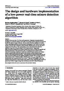
In this study we consider a LATM network as shown in Figure 1. The membership of the LATM may be determined by the physical port to which a station is connected. If multiple stations are attached t o the same ATM physical port they can be distinguished by the selector field (SEL)[figure 21 of the ATM end point address. We assume that every pair of ports in the LAN are connected by permanent virtual channels. However, since a port may host multiple IP stations every pair of hosts may not have a VC between them. The entire LATM network is configured as a single logical IP subnetwork (LIS). All stations in an LIS share the same IP network/subnet address and can communicate directly over ATM. Stations out side LIS are accessed via
'This work was done when the author was visiting Bell Communication Research. 0-7803-1825-0/94$4.00 0 1994 IEEE
H. Jonathan Chao Polytechnic University Brooklyn, NY 11201
1326
'Address Resolution Protocol
I
.0.C
m 0 . t
I of the VC and VCIO is the VCI seen at the output end.
A m Bwitch
Ethernet Hosta
Figure 1: A local ATM network. Figure 4: IPC interface. The key components of the IPC are shown in Figure 4. It consists of a table which will be referred to as the VCI Table. This table maps an input VCI to an output VCI and an output port. Before the cells are released to the switching fabric, the VCI is replaced by the output VCI and the output port is appended for self routing. The VCI Table can be modified by the switch controller. In t h b design we use the AAL5 adaptation layer. Each Figure 2: ATM Address Format. port has one AAL51ATM processor which is shared if there are multiple hosts on the same port. The advanan I P router. This paper addresses the problem of send- tage of AAL5 is that the adaptation layer overhead is ing IP datagrams to stations within the same LIS. The minimal and all of the 48 bytes of the payload can be problem of sending IP datagrams t o hosts outside LIS will used to carry IP packets. In contrast, the AAL3/AAL4 has only 44 bytes per cell available for IP packets. Howbe addressed in a subsequent paper. ever, the disadvantage of AALC is that only one message per VCI can be processed at a time since there is no message identifier (MID) field as in AAL3/AAL4. As mentioned earlier, the problem of sending I P datagrams to stations within the same LIS is essentially that of address resolution. The sending host need to resolve the IP address of the destination host t o its ATM address and if no ATM layer connection exists between these two host a VC needs to established. In the following two sections we give the design details and internal architecture of the connectionless server which performs these tasks.
3 I
Central Server Based Approach
In this scheme we maintain a server, referred to as the Connection Manager (CM), on the ATM switch which manages PVCs pre-allocated between pairs of ports and dynamically assigns VCs between communicating hosts. Figure 3: ATM switch model. " The CM also plays the role of the address resolution The internal architecture of the ATM switch is shown server. There are two key requirements in this S & X I - I ~ : in Figure 3. All input and output ports have controllers, referred to as IPC (Input Port Controller) and OPC (OutThe CM be placed on a well known vc known to Each switch has a Put Port everyone. We will MSume that hosts on every port controller, which, among other important functions, d o u8e vcI to send m ~ a g e to s the CM. cates VCs and can modify tables maintained in the port 0 Between port P-U, the home port of the CM, and controllers. Each VC is identified by two VCIs, namely every other port in the switch there is a VC. In the (VCI',VCIo). VCZ' is the VCI used at the input end
.
-
1327
3. The host interface must be able t o discriminate befollowing discussion we assume that the CM uses tween an IP packet and a packet that is in reVCI - U p to send messages to hosts on port P. sponse to an address resolution query. Note that the The second requirement guarantees a return path from AALB/ ATM processors can perform this discrimthe CM to the host when the latter sends an address ination using the VCI since all address resolution translation request. Also, note that this requires a total queries and responses have predesignated VCIs. of N 1 VCIs, where N is the number of ports. There are two main components in this scheme, namely the host interface, and the CM which also performs address reso- The Connection Manager lution. Discussed below are the functions performed by The connection manager plays the dual role of managing these components. and allocating VCs between pairs of communicating hosts as well as aserver for address resolution. As we mentioned The Host Interface earlier, the design of the connection manager is general Figure 5 shows the functional semantics of the host inter- enough to be easily enhanced for a SVC based LATM face. The host interface maintains a cache, in the trans- network. The architecture of the connection manager is shown mitting part, referred to as the Host Table (HT) which in Figure 6. It consists of the following tables: maintains a map of IP addresses to the VCIs.
+
0
0
0
0
nee List : This is a list of unallocated VCs between each pair of input and output ports. Routing List : This is a table of IP source destination pairs and the corresponding allocated VCs.
Port Address : This table maintains the mapping from IP addresses of hosts to their current port addresses. Reserved VCI Table : This table contains the list of reserved VCIs between the CM’s port and every other port.
I
Figure 5: Host interface model. When the host needs to send a packet to a destination IP host, it obtains the corresponding VCI from the AT table and passes the IP packet and the VCI to the AAL5f ATM processor, which creates the ATM cells and passes them on to the port controller. If the host table u v a h m does not have an entry for the destination IP host, the host requests the CM for address resolution which may require assignment of a new VC between the hosts. The following points are noteworthy. 1. If there are multiple hosts on a port, the common interface which performs the AAL5/ATM processing can send the reassembled packets to the appropriate host. Figure 6: Tables and data structures in the Connec2. If the hosts are interconnected by a shared media in- tion Manager. terconnect, the shared interface can encapsulate the assembled packet in the appropriate medium access The messages exchanged between the hosts and the layer frame. CM are less than 48 bytes, and, as a result, they fit into I
1328
Type Query
Field 1 IP address
Field 2 IP address
Field 3
Reply
IP address
IP address
VCI
Add
IP address
Port Address
-
Comment From IP host to CM to obtain VCI for a destination IP address. From CM to IP host to allocate a new VCI for a destination IP host. From host to CM to add a new host.
-
Table 1: Messages and their formats required for address resolution.
the payload of one ATM cell. A list of the messages ex- Discussion changed between the hosts and the CM is listed in Table In the last section we illustrated the main idea behind the 1. scheme. In the following paragraphs we consider some The interactions between different components are exadditional features. plained below. 1. Adding a new host: When a new host with IP ad-
dress IP-N is added to port P-N that the host knows the port to which it is connected. It sends a message to the CM to update the table corresponding to the port identifier. This mesage has the following information.
Messages Exchanged
Consider that a host with the IP address IP-S, connected to port P-S, wants to send an IP packet to a destination host IP-D on port P-D. If a VC already exists between this pair of hosts and the corresponding entry exists in the HT of IP-S, the host interface simply forwards the VCI and the IP packet to the AAL5/ATM processor, which performs all the necessary functions and sends the ATM cells to the port controller. If the HT in IP-S has no entry corresponding to IP-D, the packet is dropped and an address resolution protocol is initiated. This results in the following query message to the CM. Header VCI VCI-U
Header VCI VCI-U
The HT is built as the connections are established. Rebooting a host: In this case the HT is invalidated and the host can start like a new host.
Pori mobility: When a host moves to a new port it invalidates its ET. It then sends an add host message to the CM. The CM upon receipt of this message updates the Port Address table and invalidates all entries in the b u t i n g List in which the host appears either as a source or as a destination and returns the VCIs to the Free List. The host rebuilds its cache like a new one.
Payload
Type Query
I Field 1 I Field 2 I Field 3 I IP-S I IP-D I -
If there is an entry in the routing list for the particular source destination pair, then the CM responds to the source host with the following message. Header VCI VCI-Up-s
ET as a cache: Similar to the address resolution table [2], the HT can be operated as a cache in which the entries are invalidated after a certain time period.
Payload
Type Reply
I Field 1 I Field 2 I Field 3
I
IP-S I IP-D
Payload Type I Field 1 I Field 2 I Field 3 ADD I IP-N I P-N I -
I VCI'
VCI-Up-s is the reserved VCI between the CM and the port P-S, and VCI' is the input VCI for the source destination pair in the routing list. If there is no entry in the allocated list then the CM assigns a new VC from the free list for the appropriate port pairs and follows the same procedure aa above. If the free list is empty, the address resolution protocol fails and a switch management protocol is initiated to remap the allocated VCs and/or allocate new VCs.
4 Distributed Implementation of the CM In this scheme the address resolution is performed using a set of mutually cooperating servers, one on each port. There are four key featurea of this scheme:
1329
0
Each port has a server which performs the VC management and address resolution.
Each host on a port can send and receive messages to 5 Concluding Remarks and from the local CM on a well known VCI denoted We have discussed in details the architecture of the adby VCI-UL. dress resolution service and other issues related to transEach CM can broadcast to all the peer CMs using a mission of IP datagrams in a local ATM network. There are lot of other issues which need to be resolved before fiwell known VCI denoted by VCI-UB. nalising the standards. Routing across multiple logical IP Each CM can reply to a peer query using a well subnets on a common ATM infrastucture, support for IP known VCI similar to that in the centralized imple- multicasting, methods of encapsulation and multiplexing are some of the topics currently being,debated by IETF mentation. and other forums. The functions performed by the host interface and the port controller in this scheme are exactly the same as References those in the previous one, the only difference is in the server architecture. Followings are the tables maintained Ramon Caceres and Peter B. Danzig and Sugih by each server. Jamin and Danny Mitzel, Characterization of Wide-Area TCP/IP Conversations, ACM SIGCOMM 1991, pp. 101-112. 0 n ee List: This is a list of free VCs from that port to all other ports. Douglas E. Comer, Internetworking with 0
0
Routing List: This is a list of already existing connections originating from the hosts on that port.
T C P / I P , Volume 1, Principle, Protocols, and Architectures, Prentice-Hall, Englewoods Cliffs, New Jersey 07362.
Reserved VCI Table: This is a list of VCIs used to communicate with the servers on other ports.
J. Postel, Internet Protocol, RFC 791, Information Sciences Institute, September 1981. D. Piscitello and J. Lawrence, The Ttansmission of IP Datagrams over SMDS Service, RFC 1209, Infomation Sciences Institute, March 1991.
Messages Exchanged
Suppose that a host with IP address IP-S, connected to port P-S, wants to send an IP packet to a destination host IP-D, connected to port P-D. If a VC already exists between these host pairs and the VCI is known t o the source, it simply forwards the VCI and the IP data unit to the AAL5 entity, which performs the necessary functions and forwards the ATM cells to the port controller. If the HT in IP-S does not have an entry corresponding to IP-D, the packet is dropped and an address resolution protocol is initiated. The source IP-S sends a query message to its local CM. The CM upon the receipt of this message broadcasts it to all the other servers in the LAN. The server managing the port to which the host with the IP address IP-D is currently attached replies with the port address. Once the source CM knows the port address of the destination host, it selects an un-allocated VC connecting P-S and P-D and sends it to IP-S. Upon receipt of this message the host IP-S updates its HT.
CCITT, Draft Recommendation 1.363, CCITT Study Group XVIII, Geneva, 19-29 January 1993. CCITT, Draft text for Q.93B, CCITT Study Group XI, 23 September - 2 October 1992. M. Laubach, Classical IP and ARP over ATM, RFC 1577, Information Sciences Institute, January 1994. J . Heinanen, Multiprotocol Encapsulation over ATM Adaptation Layer 5, RFC 1489, July 1993. Randall J . Atkinson, Default IP MTU for Use over ATM AAL 5 , IETF Working Draft,January 1994. D. Plummer, An Ethernet Address Resolution Protocol, RFC 826, November 1982.
Discussion A new host or a mobile host after changing its port ~ ~ 9 ciation has to register with the home port's CM. This can be done the same way as in the centralized scheme. Note that the hosts use the same VCI to communicate with the local server irrespective of their port association and hence this information can be a part of host configuration file instead of being specific to a port.
0 -
1330