for the efficient and effective transmission of astronomical images across a .... Therefore, if one bitstream is lost or damaged during transmission, the quality.
Implementation of a robust transmission system for astronomical images over error-prone links Paul Thienphrapa, Helen Boussalis, Charles Liu, Khosrow Rad, and Jane Dong Department of Electrical and Computer Engineering California State University, Los Angeles 5151 State University Drive Los Angeles, CA 90032, USA ABSTRACT The James Webb Space Telescope (JWST) is expected to produce a vast amount of images that are valuable for astronomical research and education. To support research activities related to the mission, the National Aeronautical and Space Administration (NASA) has provided funds to establish the Structures Pointing and Control Engineering (SPACE) Laboratory at the California State University, Los Angeles (CSULA). One of the research activities in SPACE lab is to design and implement an effective and efficient transmission system to disseminate JWST images across networks. In on our previous research, a prioritized transmission method was proposed to provide the best quality of the transferred image based on the joint-optimization of content-based retransmission and error concealment. In this paper, the design and implementation of a robust transmission system is presented to utilize our previously proposed methods over errorprone links. The implemented system includes three parts. First, a zero-tree based error-resilient wavelet codec is used to compress the incoming astronomical image at the sender. Tree-based interleaving is adopted in packetization to increase the system’s capability to combat burst losses in error-prone channels. Second, various error concealment approaches are investigated and implemented at the receiver to improve the quality of the reconstructed image. The transmission system uses UDP as the transport protocol, but with an error control module to incorporate the optimal retransmission with the delay constraint. A user-friendly graphical interface is designed to allow easy usage for users of diverse backgrounds.
1. INTRODUCTION One of the major goals of the NASA ORIGINS program is to determine the origins of life in our universe. To this end, the JWST, which is scheduled for deployment in 2011 as the successor to the Hubble Space Telescope, has been designed to achieve greater optical range and sensitivity than the Hubble. En route to discovering the origins of life, vast amounts of high-quality astronomical image data must be analyzed, so the JWST is expected to produce large quantities of such images for ground-based observation. Astronomers, as well as scientists in related fields, from around the world must be able to simultaneously access these images quickly in order to conduct research productively. Additionally these images must be made available for education and public outreach purposes as well. As such the design of a system for the efficient and effective transmission of astronomical images across a global network is a topic of importance. The SPACE Laboratory was established at CSULA in 1994 under funding from NASA to study some of the new technologies that need to be developed as part of the James Webb Space Telescope project1. In particular, one of the SPACE Laboratory research activities involves the design of an efficient image transmission system that is optimized for astronomical images. Due to the great optical range, sensitivity, and volume of images that the JWST will generate, as well as the marked interest by the scientific community to study these images, such a system is essential in enabling productive ORIGINS-related investigations throughout the world. By balancing the constraints of network bandwidth, time delay, and image quality, and by capitalizing on the properties of astronomical images, a novel image transmission system would allow audiences, including scholars, educators, and the general public, to maximize their respective efforts in the study of the images. This paper discusses the implementation of an astronomical image transmission system that considers the optimization of transmission using two different transmission technologies, namely content-based retransmission2, 3 and error Multimedia Systems and Applications IX, edited by Susanto Rahardja, JongWon Kim, Qi Tian, Chang Wen Chen, Proc. of SPIE Vol. 6391, 63910G, (2006) · 0277-786X/06/$15 · doi: 10.1117/12.690109 Proc. of SPIE Vol. 6391 63910G-1 Downloaded from SPIE Digital Library on 21 Jan 2010 to 128.220.159.9. Terms of Use: http://spiedl.org/terms
concealment4, the combination of which was the focus of our previous work10, in the context of astronomical images. To review, with the constraints of bandwidth and time delay, a practical image transmission system should not, and often cannot, naively attempt to transmit all packets of an image. Instead, an optimal subset of packets should be selected for transmission to produce the highest quality image at the receiver under the constraints. This idea governs the transmission decisions made by the system. The research presented in the previous paper was an extension of an earlier proposed approach to optimize the video transmission quality over lossy channels5. Due to the special characteristics of astronomical images, the error control mechanism that works for general images and video cannot yield desirable results. Hence, to optimize the performance of astronomical image transmission, its special characteristics were considered. To quantify the significance of an astronomical image packet, a novel content index was defined by jointly considering the information content of each packet, the impact of error concealment, and the characteristics of the image content. Based on the content index, a smart transmission system was designed to automatically select the most suitable error control mechanism for the input image and generate an optimal transmission policy to maximize the quality of the received image under the network constraints. Experimental results have demonstrated that the proposed approach is very effective in combating packet loss during transmission to achieve a desirable quality of the received astronomical images. Due to the practical nature of the topics described above, we consider now an implementation of the ideas proposed. The goals of such an effort are multifold. One goal is to demonstrate the validity of the newly-derived concepts via proof-ofconcept. Another goal is to gauge the performance of the approach and compare it to expectations. Performing an implementation can shed insight on possible areas of improvement in terms of both theory and implementation. The applications developed will provide a framework for the demonstration of future research in this area; finally, an implementation will introduce researchers in related fields to the technological possibilities, thereby facilitating feedback and novel research frontiers. This paper is organized as follows. Section 2 describes an overview of our proposed astronomical image transmission system. In Section 3, the implementation framework for the novel design of a smart streaming system for astronomical images is described. The results of the implementation are shown in Section 4. Section 5 summarizes the findings described in this paper and draws conclusions.
2. TRANSMISSION SYSTEM OVERVIEW Receiver
Sender
Proposed Astronomical Image Transmission System Components
Network
channel
I
Receiving & Error Checking
Dep
Feedback Mechanism
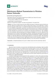
Fig 1. Overview of the astronomical image transmission system
Proc. of SPIE Vol. 6391 63910G-2 Downloaded from SPIE Digital Library on 21 Jan 2010 to 128.220.159.9. Terms of Use: http://spiedl.org/terms
As shown in Figure 1, the astronomical image transmission system consists of three major components: A smart image sending module, a robust transmission module and an image receiving and display module. The sending module will perform wavelet-based image compression and robust packetization; the transmission module will conduct cross-layer optimization to maximize the quality of the received image over lossy channels, and the receiver will perform loss detection, feedback the channel statistics, repair the received image with error concealment and display the image in a real-time fashion. The details of the three modules are described below. 2.1 Smart Image Sending Module Due to the size of astronomical images, it is necessary to perform compression before transmission. In our previous research, a comprehensive comparison was conducted to evaluate various compression methods for astronomical images11, e.g. RICE, JPEG, model-based compression, and wavelet-based compression. Wavelet-based compression is desirable due to its excellent compression performance and good features to support scalable transmission. As shown in Figure 2, our image sending module uses SPHIT-based approach for compression.
tree
Packets
I____ I 1 Hf Hf_Hf '* ___ ___
I }sitstream
Image Translorm Coefticienis
I
I
I
I
0
Fig 2. The white squares of the transform represent the various subbands; the tree structures illustrated correlate the same spatial locations across scales; one or more trees can be encoded into a bitstream
Instead of generating a single embedded bitstream, our image encoder outputs mutually independent multiple bitstreams. Each bistream comprises of a number of trees. Interleaving is utilized such that the trees contained in one bitstream are dispersed across the entire image. Therefore, if one bitstream is lost or damaged during transmission, the quality degradation will not be concentrated in one local region, which facilitates the error concealment at the receiver side. One bitstream will be enclosed by one or more packets before transmission. If each bitstream is put into one packet, independent decodable packetization is achieved. Otherwise, the packets belonging to the same bitstream are linearly dependent on each other, and the packets belonging to different bitstreams are independent. Figure 2 illustrates an example of how an image transform encoded into multiple bitstreams might be packetized. Since each bitstream is encoded in a progressive manner, the packets exhibit the linear dependence relationships shown by the arrows. This dependency relationship is an important factor in determine the best transmission scheme. Once the bitstreams are packetized, an initial prioritized transmission schedule can be created based on packet contents. As detailed in our previous work10, a metric of packet significance called reconstruction distortion has been introduced to optimize transmission for this application. Reconstruction distortion takes into consideration the importance (loss distortion) of each packet in tandem with its contribution to the error concealment process (concealment profit). Interested readers can refer to our previous paper for the details.
Proc. of SPIE Vol. 6391 63910G-3 Downloaded from SPIE Digital Library on 21 Jan 2010 to 128.220.159.9. Terms of Use: http://spiedl.org/terms
During the encoding and packetization stage, the sender calculates the loss distortion of each packet based on the image contents. This information will be stored and used for selecting the optimal transmission schedule at the transmission module. 2.2 Robust Transmission Module for Astronomical Images Since our developed software servers as a simulation platform to evaluate various transmission schemes, the transmission module contains two major parts. The first is a simulated lossy channel that emulate practical transmission scenario; and the second is a transmission system capable of sending packets, receiving acknowledgement, analyzing channel conditions and determining transmission schedule. 2.2.1 Simulated Lossy Channel The simplest lossy channel is a packet erasure channel where each packet is lost with an independent packet loss rate Pe . The packet loss rate could be a fixed value, e.g. the average packet loss rate, or a variable of transmission delay and other channel conditions. Although this independent packet loss model has been used in many researches, it is not very realistic. In our previous research, we have investigated the packet loss behavior of an astronomical image transmission system in home network and office network. Experimental results demonstrate that there exists inter-packet dependency among the losses, and this dependency relationship can be best described by Hidden Markov Model shown in Figure 3. 1 − PGL
SG
Received
P GL
1 − PBL
SB
P BL
Lost
Fig 3. Two-state hidden Markov model for image packet loss Similar to two-state Markov model, two-state hidden Markov model also has a good state S G and a bad state S B , and the transition probabilities are PGB from S G to S B and PBG from S B to S G , respectively. The most significant difference from Markov model is that the states in hidden Markov model are not corresponding to physical events in the L
L
random process. In the hidden Markov model, the packet loss rates of the two states S G and S B are PG and PB , as illustrated in Figure 3. In the simulated lossy channel, the packet loss is generated following this hidden Markov model to ensure a good simulation close to practical transmission scenario. 2.2.2 Content-based Retransmission The transmission system prioritizes the transmission of packets based on the reconstruction distortion of each packet as well as its concealment profit. Doing so ensures that packets that contribute most to the quality of the image are transmitted first, which would in turn produces the highest-quality image at the receiver in the shortest length of time. The sender assigns and attaches a unique sequence number to each packet in order to aid the receiver in reassembling the packets and determining packet loss. Transport layer error control is necessary to the success of the proposed astronomical image transmission system because not all packet loss is tolerable: some packets contain information too important to be lost. The Automatic Repeat Request (ARQ) method has been selected because it is more efficient, as packet loss is assumed to be sufficiently low. Bandwidth is conserved because ARQ does not call for data redundancy. When a packet is lost, only that packet needs
Proc. of SPIE Vol. 6391 63910G-4 Downloaded from SPIE Digital Library on 21 Jan 2010 to 128.220.159.9. Terms of Use: http://spiedl.org/terms
to be retransmitted. While the ARQ method may intermittently result in delays, such delays are tolerable for the purposes of image browsing. Furthermore, ARQ utilizes the feedback channel already required by the application. Building upon the selection of ARQ, the NACK-based variant has been chosen for this system. Because a low packet loss rate is assumed, the NACK-based option offers great efficiency because the sender only retransmits explicitly lost packets while assuming success otherwise. Very few feedback messages need be sent under the low packet loss assumption, thereby conserving bandwidth. The transmission module will estimate the packet loss rate using the feedback information. The loss rate estimation is conducted via linear prediction which is widely adopted in many transmission systems:
p e = ap e' + (1 − a) p e '
p e is current packet loss rate, p e is the cumulative packet loss rate that is known by previous feedback information, and a is a constant selected empirically. where
The estimated packet loss rate will then be used to calculate the reconstruction distortion. The best transmission scheme will be determined by the fast decision approach described in 10. 2.3 Real-time Receiving Module The responsibilities of the receiver begin with receiving packets sent by the sender over the network. As the receiver accepts incoming packets, it must extract the sequence identifier from each packet in order to appropriately reconstruct the data stream. The receiver will also use the sequence identifiers to detect the loss of any packet may have occurred; it will notify the sender of these packet losses via a feedback channel in a manner to be described shortly. For this application, the concept of packet loss is abstracted to encompass both dropped packets and bit errors. Once a packet loss is detected, an NACK will be sent back only if the receiver determines that the retransmitted packet can arrive in time for display. This judgment is made through the following inequity:
Tc + eRTT ≤ Td where Tc is the current time, Td is the deadline for display and eRTT is the estimated round trip time calculated via the following equation:
eRTT = bRTT + (1 − b)eRTT where RTT is the average round trip time that is known, and b is a selected constant.
To enhance the quality of the received image, error concealment will be applied during the image decompression process. Error concealment is a prediction-based error control method using the received contents in the surrounding locale. This technique can be used for astronomical images because the transform coefficients of such images vary gradually across the transform domain. Error concealment is favorable because it does not require additional bandwidth while consuming negligible computation time. Although error concealment relies on retransmission of dependent packets, and hence is more delay-prone, the minor expected delays are tolerable for this image browsing application.
3. TRANSMISSION FRAMEWORK IMPLEMENTATION AND RESULTS The proposed system for the optimal transmission of astronomical images over lossy networks described above has been implemented to demonstrate the novel concepts and illustrate their results. The program, whose main window is shown below in Figure 4, is intended to have an intuitive interface that allows a user to conveniently open astronomical images stored in the FITS file format for the purposes of sending and receiving them using the proposed techniques.
Proc. of SPIE Vol. 6391 63910G-5 Downloaded from SPIE Digital Library on 21 Jan 2010 to 128.220.159.9. Terms of Use: http://spiedl.org/terms
FITS AppIkti 5(it _______________________ DWd . s—
.=.tJ.2sJ
_____________
•.nBIflNAL 64(-I6.Bt (603.0 KB) — COMPRESSED 64(- I6.rt (42.7 KB)
Fig 4. Astronomical image transmission system implementation main window
The program allows a user to set various parameters used in the compression and transmission processes. The primary feature of the main window shown above is the main frame, in which original, compressed, and received images are displayed. Each image is displayed in its own sub-window with a descriptive title that includes information on the file name, file size, and whether the image is in its original or compressed state. Displayed on the bottom right corner of the main window is a floating dialog that displays the current parameters being used and the image transfer progress As described in previous sections, our developed software supports rich functionalities and allows users to evaluate the performance of various compression, transmission, and error control methods. 3.1 Implementation and Evaluation: Compression Figure 5 shows a dialog box that allows users to change compression parameters. Various wavelet transform types are enabled in our image codec, and the user can also select other parameters such as the level of wavelet transform, the target bit rate, etc. The compressed image will be displayed at the sender side-by-side with the original image for direct visual comparison. In addition, PSNR will be calculated to give an objective quality measurement. Figures 6 and 7 provides examples of evaluating the effects of different wavelet transforms and different transformation levels in compressing astronomical images. In figure 6, compressed images using Haar wavelets and float point DB 5 wavelets are compared. One can see that the performances of these two types of wavelets are similar for this specific image with large empty background and very little detailed information. Figure 7 compares the effect of wavelet transformation levels on an image with lots of details. In this case, applying more level of transforms can improve the quality of the compressed image. In these examples, other compression parameters including the target bitrates are the same.
Proc. of SPIE Vol. 6391 63910G-6 Downloaded from SPIE Digital Library on 21 Jan 2010 to 128.220.159.9. Terms of Use: http://spiedl.org/terms
Compression Parameters.
.2sJ
Pleace celect the decired encoding/decoding parametero or celect the detault valuec.
Detault '/alueo F Wavelet Tranotorm Type: Floating-point D 8-5 T ranotorm
Wavelet Levelo:
flitrate (hpp):
I.zJ Packetization:
liE Multiple B itztreamz
UK
Cancel
Fig 5. Set codec parameters dialog
(a)
(b)
(c)
Fig 6. Performance Evaluation of different wavelet transforms in compression : a) Original image; b) Haar Transform; and c) Float point DB-5 Transform
r
(a)
(b)
(c)
Fig 7. Effects of wavelet transform levels: a) original image; b) 2 levels; and c) 8 levels
Proc. of SPIE Vol. 6391 63910G-7 Downloaded from SPIE Digital Library on 21 Jan 2010 to 128.220.159.9. Terms of Use: http://spiedl.org/terms
%4rn1
Using SPHIT-based image codec, the target bit rate can be met in an accurate manner. Figure 8 illustrates images compressed at different bit rates. Please note that the image used is for illustrative purposes; differences are more pronounced in this type of image than in many astronomical images.
Fig 8. Original test image, and images compressed at 1.0 bpp and 0.2 bpp
3.2 Implementation and Evaluation: Transmission Scheme with Error Control The transmission module is also implemented with a flexible and open architecture. UDP/IP is used as the basic transmission protocol, and our proposed content-based retransmission is implemented on top of it to perform error correction. The functionality of the implemented transmission module can be briefly described as follows. Opening an image automatically causes it to be ready to send to anyone who requests it. The parameters to be used for the transmission can be set in the Set Transmission Parameters dialog box. The user can select the parameters in the dialog box to indicate the property of simulated channel. Although the image will be sent through real Internet using UDP port, to enforce a certain packet delay and loss pattern, a regulated data rate and simulated packet dropping following the packet loss model is enabled at the sender. To request for image transmission, the user need to specify the IP address of the sender. If a valid transmission program is running at the specified machine, a connection will be made and the user can select the Receive Image option from the Transmission menu to receive the image. Otherwise, error message will be generated to inform the user of the reason of operation failure. To provide a good platform for error control research, three different packet loss model are implemented in our software. The first is the Lossless model which add no artificial loss to the transmission. Using this model, the user can view the effect of image transmission over Internet, but has no control of the packet loss pattern. The second one is the Independent Packet Loss model. User can specify the packet loss rate to see the transmission results under different loss conditions. The third one is the two-state Hidden Markov model which simulate a burst loss channel. Again, the user can specify the parameters such as the averaged packet loss rate, burst length, etc. Figure 9 illustrates the received images via hidden Markov channel and independent packet loss channel, respectively. It is obvious that the burst loss channel leads to worse image quality even when interleaving is used. Figure 10 compares the transmission results for the same type of channel under different packet loss rate. One can see that the flexibility design of the interface is very desirable in the study of transmission scheme.
Proc. of SPIE Vol. 6391 63910G-8 Downloaded from SPIE Digital Library on 21 Jan 2010 to 128.220.159.9. Terms of Use: http://spiedl.org/terms
#1
t.
1
(a)
'-S
(b)
(c)
it
1-
—
lI•Il,
-,
p
Fig 9. Effect of different lossy channel: a) Original test image; b) Run through a Two-state Hidden Markov; and c) Run through an Independent Packet Loss model.
(a)
(b)
Fig 10. Effect of different packet loss rates in Independent Packet Loss channel: a) with 5%; and b) 20% loss.
In addition to the transmission channel model, users can select to use different error control methods and evaluate their performance in different transmission situations. For instance, the user can set the rate at which image data is sent over the network, as well as the delay in transmission. This allows for the simulation of the proposed image transmission techniques under different network conditions. This works in tandem with the time delay constraint. If the rate is low and delay is high, less data will be sent during that time period. Since the bitstream is embedded and the most important packets are sent first, the result is that a complete but lower-quality image is received. Figure 11 shows the impact of the delay constraint on the received image when retransmission is used for error correction. And Figure 12 shows the effect of error concealment. Apparently, the image quality is significantly improved by error concealment. During the transmission process, a floating window will be shown by default in the lower right-hand corner of the main window. This window, the Status and Statistics window, displays a variety of interesting information regarding the current state of the application, such as the codec parameters selected, transmission parameters chosen, and the real-time progress of any outgoing or incoming image data. The information displayed in the window is useful to analyze the transmission results.
Proc. of SPIE Vol. 6391 63910G-9 Downloaded from SPIE Digital Library on 21 Jan 2010 to 128.220.159.9. Terms of Use: http://spiedl.org/terms
I w[r
a
Fig 11. High-speed, low delay vs. low-speed, high delay transmission
Fig 12. Highly erroneous received image, without and with error concealment
4. CONCLUSIONS This graphical user interface implementation of the optimal transmission of astronomical images, to be produced by the James Webb Space Telescope, has proven to be a highly effective tool in demonstrating validity and utility of the research concepts studied. On one level, it demonstrates proof-of-concept of the various wavelet transform and encoding algorithms along with their variable parameters. It also proves the working state of the principals of optimal image transmission. On another level, this implementation demonstrates the practicality of the aforementioned studied research concepts in a real-world environment. This is true to the extent that a user-friendly application has been developed to utilize these concepts. This application also constitutes the framework for analyzing the effects of various compression algorithms, transmission mechanisms, and their associated parameters. It can be used as a tool to quickly and conveniently compare experimental image results both visually and quantitatively. For example, we observed that the techniques worked well on
Proc. of SPIE Vol. 6391 63910G-10 Downloaded from SPIE Digital Library on 21 Jan 2010 to 128.220.159.9. Terms of Use: http://spiedl.org/terms
astronomical images so much that more detailed, non-astronomical images were needed for illustrative purposes. Further analysis of the current theories is enhanced, and extensions of the concepts are readily possible. Finally, a user-friendly tool has been developed that cloaks the complexities of all the topics involved in this area of research. This application not only allows a novice user to conveniently view FITS astronomical images, it allows a user to perform sophisticated processing and view the results of the processing without requiring any prior knowledge of the science. Thus the dissemination of information and the publicity of cutting-edge concepts are greatly facilitated, opening the channels towards advanced research and early feedback.
ACKNOWLEDGEMENT This work was supported by NASA under Grant URC NCC 4158. Special thanks go to all the faculty and students associated with the SPACE Laboratory.
REFERENCES 1. 2. 3. 4. 5. 6. 7. 8. 9. 10. 11.
H. Boussalis, M. Mirmirani, K. Rad., M. Morales., E. Velazquez, A.G Chassiakos, J.A Luzardo, "The Use of Decentralized Control in the Design of a Large Segmented Space Reflector," NASA URC Technical Conference, Albuquerque, NM. Febuary 1997. J. Dong and Y. F. Zheng, “Content-based Retransmission of 3-D Wavelet Video on the Internet”, in Proc. IEEE Int. Conference on Information Technology, Coding and Computing, Apr., 2002. B. J. Dempsey, J. Liebeherr, and A.C. Weaver, “On Retransmission-based Error Control for Continuous Media Traffic in Packet-switched Networks,” Computer Networks and ISDN System, Vo. 28, pp.719-736, 1996. Q. F. Zhu and Y. Wang, “Error Concealment for Video Communication,” in Compressed video over networks, New York: Marcel Dekker, 2001. Y. Zhao, S. Ahalt and J. Dong, “Content-based Retransmission for Video Streaming System with Error Concealment”, SPIE Defense and Security Symposium, Orlando, April, 2004. R. L. White, J. W. Percival, “Compression and Transmission of Astronomical Images.” M. A. Nieto-Santisteban, D. J. Fixsen, J. D. Offenberg, R. J. Hanisch, et. al., “Data Compression for the NGST.” J. K. Rogers and P.C. Cosman, “Wavelet Zerotree Image Compression with Packetization,” IEEE Signal Processing Letters, Vol. 5, no. 5, pp. 105-107, 1998. X. Wu, S. Cheng, and Z. Xiong, “On packetization of Embedded Multimedia Bitstreams,” IEEE Transaction on Multimedia, Vol. 3, No. 1, pp. 132-140, 2001. J. Dong, P. Thienphrapa, H. Boussalis, C. Liu, and K. Rad, “Content-based Retransmission with Error Concealment for Astronomical Images,” Proceedings of SPIE Multimedia Systems and Applications VIII, 2005. S. Fellorina, H. Boussalis, C. Liu, K. Rad and J. Dong, "Performance Comparison of Compression Methods for Segmented Space Reflector Telescope Image,” 7th World Multiconference on Systemics, Cybernetics and Informatics (SCI 2003), Orlando, Florida, July 27-30, 2003.
Proc. of SPIE Vol. 6391 63910G-11 Downloaded from SPIE Digital Library on 21 Jan 2010 to 128.220.159.9. Terms of Use: http://spiedl.org/terms