A large domain can be partitioned into ... isting Domain Name System . .... Encryption Standard (DES), which is an inexpensive symmetric key cryptographic.
Implementation of a Scalable Context-Aware Computing System Tamer Nadeem, Adel Youssef, Suman Banerjee, Moustafa Youssef, Sulabh Agarwal, Kevin Kamel, Andrzej Kochut, Christopher Kommareddy, Pankaj Thakkar, Bao Trinh, A. Udaya Shankar, and Ashok Agrawala MIND Lab, UMIACS and Department of Computer Science University of Maryland, College Park, MD 20742, USA {nadeem, adel, suman, moustafa, sulabh, kamelkev, kochut, kcr, thakkar, bao, shankar, agrawala}@cs.umd.edu
Abstract. Context-aware computing involves the automatic tailoring of information and services based on the current location of the user. In this paper, we describe our experience in implementing Rover, a system that enables location-based services, as well as the traditional time-aware, user-aware and device-aware services. To achieve system scalability to very large client sets, Rover servers are implemented in an “action-based” concurrent software architecture that enables fine-grained application-specific scheduling of tasks. We have demonstrated its feasibility through implementations for both outdoor and indoor environments on multiple platforms. Keywords: ubiquitous, context-aware, location-based, operational-law.
1
Introduction
Context-aware computing requires the automatic tailoring of information and services based on the current context of the user. The context of the user typically consists of a set of user-specific parameters including his location, the characteristics of the access device and interface, and the interests of the user, usually represented in an user profile. The different technology components needed to realize context-aware computing are present today, powered by the increasing capabilities of mobile personal computing devices and the increasing deployment of wireless connectivity. What has hindered its ubiquitous deployment is the lack of system-wide integration of these components in a manner that scales with large user populations. In our prior work [10], we had described an architecture of such a context-aware computing system, called Rover, and had discussed its applications, devices, and users. In this paper, we focus on our implementation experience of this system for both indoor and outdoor environments. Rover enables services with characteristics: a) Locationaware, in addition to the more traditional notions of time-aware, user-aware, and device-aware. b) Available via a variety of wireless access technologies and devices. c) Scales to a very large client population. In the next section we present an overview of the Rover system. In Section 3 we describe the our implementation of the system. We explain the functionality of the system in Section 4. In Section 5, we briefly comment on our experiments and analysis to test system scalability. We describe some related projects in Section 6 and finally conclude in Section 7.
2
amer
T
Nadeem
et
al.
Inter Controller protocols
Rover system
Rover Controller Database
Internet/PSTN Local
Firewall
Network
Streaming Media Unit Base Stations Location Server
Client Devices
Rover system
Rover system
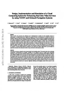
Fig. 1. Physical architecture of the Rover System
2
Overview of Rover
A Rover system, depicted in Figure 1, consists of the following entities: – End-users of the system. Rover maintains a user profile for each end-user, that defines specific interests of the user and is used to customize the content served. – Rover-clients are the client devices through which users interact with Rover. Rover maintains a device profile for each device, identifying its capabilities and thus, the functionality available at that device. – Wireless access infrastructure provides wireless connectivity to the Rover clients. – Servers implement and manage the various services provided to the end-users. The server system consists of the following set of devices: • Rover controller: is the “brain” of the Rover system. It provides and manages the different services requested by the Rover clients. It schedules and filters the content sent to the clients based on user and device profiles and their current locations. • Location server: is a dedicated unit responsible for managing the client device location services within the Rover system. • Media manager: coordinates direct audio communication between different Rover clients. • Rover database: stores all content delivered to the Rover clients. • Authentication server and security manager1 : authenticates users before connecting them to the Rover controller. • Logger: interacts with all the Rover server devices and receives log messages from their instrumentation modules. Rover system achieves scalable performance using a new fine-grained real-time applicationspecific scheduling called the Action Model (described in [10]). In this model, scheduling occurs in atomic units called actions. An action is a small piece of code that has no intervening I/O operations. The Action model avoids the overhead of thread context switches and allows more efficient scheduling of execution tasks. 1
The Authentication server is not shown in Figure 1.
Scalable Context-Aware Computing System
3
A Rover system represents a single domain of administrative control that is managed and moderated by its Rover controller. A large domain can be partitioned into multiple administrative domains each with its own Rover system, much like the existing Domain Name System . For this multi-Rover system, we define protocols that allow interaction between the domains to ease user roaming. In the next section we describe our prototype of the Rover system that has been implemented in the University of Maryland campus.
3
System Implementation
In our prototype implementation all system components were developed on Linuxbased platforms in C++ and they can easily be ported to any other operating system as well. Rover Controller Scalability and reliability are the most important factors required in such system. It is implemented using the action model. Each independent transaction of the Rover controller with the clients is called a server operation. A server operation consists of a sequence (or more precisely, a partial order) of actions interleaved by asynchronous I/O events. Rover Database The database is implemented using a standard SQL language (MySQL2 ). It consists of two different components — the relational data and the spatial data. All attributebased data, e.g. user and client states, are stored in the relational component. All spatial information, e.g. floor plan of a building, are stores in the spatial component in a hierarchical structures. Vector-based image is used to represent spatial data. Rover Clients The Rover clients are implemented on the Compaq IPAQ devices running the familiar distribution of Linux for handheld devices. The user interface is implemented using GTk++ (Figure 2). Media Manager Media manager enables Rover clients to establish direct audio communication channels, independent of the Rover server system. We have defined a protocol called Click & Connect that allows users to easily initiate voice communication with each other. The protocol is so named because an user can directly click on the icon representing another user to initiate voice communication. The Media Manager arbitrates the handshaking process between two clients to provide a degree of organization. Wireless Infrastructure University of Maryland has a IEEE 802.11 wireless network widely deployed across the campus, which we used for all wireless communication to and from the Rover clients. We also deployed some additional base stations in the campus to increase the 2
Any other relational database could replace MySQL since we do not use any particular feature of it.
4
amer
T
Nadeem
et
al.
User
Space−dependent Trigger
Active Chat Session
Query Result
Users Query Area
User
(a)
(b)
(c)
(d)
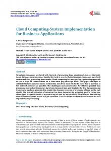
Fig. 2. Rover client screen shots taken from a demonstration at the McKeldin mall of the University of Maryland campus. (a) Rover client running the client software showing the mall map. (b) A notification to the client about a nearby food stall. The user associated with the client had previously set a trigger notification request when he is close to a food stall. (c) The user had issued a query operation about the sites of interest in his vicinity. On receiving the response from the Rover system, the client has highlighted the relevant sites. (d) An active chat session between this user and another user is marked as a dotted line connecting both users.
reachability of Rover in areas not covered by the university wireless network. Location Server The location server is responsible for storing and managing user locations in the Rover system. The system is designed to work in both indoors and outdoors environments. We have experimented with RF-based systems that infer the location of a device based on the signal strength of received RF signals of IEEE 802.11 wireless LAN frames. In our RF-based techniques, the user location of a client is obtained without the use of any additional hardware. It thus provides more ubiquitous coverage in campuslike environments that already have a rich wireless LAN coverage for data transport. This can be contrasted to alternative Infra-red tag-based systems [11, 1] or ultra-sonic emitter and receiver based systems [9] in which additional devices need to be attached to the infrastructure and the clients. We have developed different RF-based techniques in the context of the Rover system. Techniques are categorized into: – Radio-map Techniques: Work in 2 phases: an offline phase and a location determination phase. During the offline phase, the signal strengths received from the access points, at selected locations in the area of interest, are gathered as vectors and tabulated over the area. During the location determination phase, the vector of samples received from each access point is compared to the radio-map and the ”best” match is returned as the estimated user location. We used two methods to calculate the best match: • K-Nearest Neighbors (KNN): A voting mechanism based on a distance function is used to estimate the best user location. • Probabilistic Clustering-based: The Baye’s theorem is used to select the most probable location of the user. Refer to [14] for more details. – Model-based Techniques: The relation between the signal strength received from an access point and the distance to this access point is captured by some function
Scalable Context-Aware Computing System
5
(model). By using three or more access points, the user location is estimated. Two methods are used: • Minimum Triangulation: Given each access point i, the distance (di ) between the receiver, located at x, y, z and the access point, located at xi , yi , zi , is modeled as: d2i = (x − xi )2 + (y − yi )2 + (z − zi )2 = vki where vi is the strength of the received signal, and k is a constant. • Curve Fitting: The received signal power is modeled as: P L(d)[dB] = A + B log(d) A = P L(d0 )[dB] − 10n log(d0 ), and B = 10n where PL is the received power, d is the three dimensional path length to the transmitter, d0 is a reference distance, and n represents the path loss exponent. Using curve fitting techniques, A and B are estimated for each access points. For indoor environments, we found that radio-map based techniques achieve better accuracy than model-based techniques. This is because the relation between the signal strength and distance in indoor environments is complicated by to the multi-path effect and other phenomena which are difficult to capture by simple models. On the other hand, model-based techniques have the advantage of not depending on the calibration process required to build the radio-map. This advantage favors model-based techniques in outdoor environments, where the relation between signal strength and distance can be captured by simple functions and the coverage area is large making building the radio-map a time consuming process. Security Manager The Rover system inherits the vulnerability of the IEEE 802.11 wireless communication system such as unauthorized access, non confidential, and non integrity. Therefore, we have implemented different security mechanisms to protect client interactions. – Client-Server Security: A session based security protocol, Secure Sockets Layer (SSL) is used to secure the channels between the clients and the server. – Chat (peer-peer) Security: The direct audio chat sessions we employ the Data Encryption Standard (DES), which is an inexpensive symmetric key cryptographic system. The session key is transferred using the SSL-protected secure channel.
4
System Functionality
The Rover system provides different capabilities to the users, which can be categorized as follows: – System Admin Operations are available only to the authorized system administrator. These set of operations are used to monitor, manage, and query users, devices, and Rover system. – User Access Operations are the basic set operations that every user avails to access the Rover system. – Trigger Operations allow users to set context-specific alerts. The triggers are activated based on user interests and depend on current time and/or location of the user. When the trigger condition is satisfied the Rover server system sends appropriate notification to the particular user (Figure 2(b)).
6
amer
T
Nadeem
et
al.
– Query Operations allow users to acquire information about different aspects of the system and the environment. Figure 2(c) shows a client screen shot in response to a client query on sites of interest in its vicinity. – Location Update Operation inform the server system about the client’s location. – Audio Chat Operations enable direct audio communication between clients. Audio chat between clients is initiated with the coordination of the Media Manager. Once an audio chat is initiated, the clients interact directly with each other without intervention of the Rover server system (Figure 2(d)).
5
System Performance
To asses the performance and scalability of the Rover System we take two approaches: a) Active Monitoring where we instrumented the controller to collect different performance statistics (e.g. queue lengths for each component, the response time for each operation, etc.). b) Passive Monitoring which is described in this paper.
Response Time
C
B
Slope = D max
A Controller
Database D
Clients
Wireless Network
Central Subsystem
(a)
-Z
N*
Number of Clients
(b)
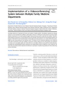
Fig. 3. Passive monitoring analysis: (a) Performance model for passive monitoring. (b) Typical asymptotic bounds.
5.1
Analysis using Passive Monitoring
In this approach, no instrumentation code is introduced in the server system. Instead, we use a client load generator to stress test the server and observe two different metrics — the response time obtained by individual clients and the number of clients that can simultaneously served by the system without significantly impacting the performance of the clients. We model the Rover system as a single-server multi-client system as shown in Figure 3(a). The Rover System is modeled as a central subsystem consisting of two devices, the Rover controller and the Rover database, and N terminal subsystems. Each of the N terminals is a client of the Rover System and perform the cycle of issuing a request, waiting for the response and processing the response (think time). Wireless network models the communication channel between the server and the clients. Since we are interested in assessing the performance of the Rover system we do not explore the affects of communication channel in this paper. Using a technique called operational law [5] to analyze such systems, it can be shown that the response time observed by clients increase marginally with increasing
Scalable Context-Aware Computing System
7
the number of clients up to a critical client population. Let D denotes the time required by the system to process a single client operation, and Dmax denotes the time required at the bottleneck server of a multi-server system. For the single server model, Dmax = D. If N ∗ indicates the critical number of clients that the system can support without impacting the response time for the clients and Z the think time used by the clients between operations, then operational analysis suggests that: N∗ =
D+Z Dmax
(1)
The graphical representation of N ∗ is shown in Figure 3(b). 5.2
Experiment Configuration
The central subsystem runs on Pentium IV 1.5 GHz desktop machine with 256 MB of RAM running the Linux OS with kernel version 2.4.7. A second machine is used to behave as a set of clients (client loader). The client loader runs on a Pentium III 800 MHz laptop with 128 MB of RAM and running a Linux OS with kernel version 2.4.2. The client machine uses 802.11b wireless network to connect to the network. The response time for each operation were collected as observed at the database, the controller and the client (points A, B, C respectively in Figure 3(b)). Instead of collecting response time for each of the system operations, we experimented with three different operations representing three different categories: 1. GetAllLoginUsers: Gets the position of all users who are logged into the system. This operation is controller intensive and does not involve the database. 2. VectorMap: Gets the vector map of an area. This operation is computationally intensive at the database side. 3. Locate: Locates the object containing the given point. This operation involves the database though it is not very computationally intensive at either the database or the controller sides. 5.3
Results and Discussion
GetAllLoginUsers Figure 4(a) shows the response time, at the controller, plotted against the number of clients in the system for different think times (Z = 100ms, 200ms, 300ms). The total service demand time, D of the controller is observed to be around 300 microseconds. For only one device in the system Dmax = D. Using Equation 1 where D = 300 microseconds and a think time Z = 200 milliseconds, we get N ∗ to be approximately 667 requests. Hence the server can support 667 requests without any significant delays. In an actual deployment, the think time would be of the order of 10’s of seconds and that would give an even higher value of N ∗ (of the order of thousands of clients). Figure 4(b) shows the response time behavior of both the controller and the client when the think time is Z = 200 milliseconds. As the graph shows the controller graph stays almost horizontal as the number of clients are increased which shows the controller can handle a large number of clients. On the other hand, the client graph grows with the number of clients. This can either be due to the effect of the wireless hop involved or the processing involved at the OS level. The performance of the 802.11b
8
amer
T
Nadeem
et
al.
1800
60000
Z=100ms Z=200ms Z=500ms
1600
Client Controller
50000 Response time (us)
Response time (us)
1400 1200 1000 800 600
40000
30000
20000
400 10000 200 0
0 0
5
10
15
20 25 30 Number of clients
(a)
35
40
45
50
0
5
10
15
20 25 30 Number of clients
35
40
45
50
(b)
Fig. 4. GetAllLoginUsers operation: (a) Controller response time, and (b) Response time when Z=200ms.
wireless network has not been taken into account and is left for future work. VectorMap Figure 5 shows the response time at the different Rover components. For the database the total service demand time is observed to be around 0.5 seconds. Using equation 1, we can predict the knee-point to be at N ∗ = 3 with a think time Z = 1 second. We should note that the VectorMap operation is an infrequent operation and has been used only to assess the performance of the system in the extreme case. In an actual deployment, the duration between subsequent VectorMap operation requests (Z) would be in the order of minutes. The difference in the database response and the controller response (Figure 5(d)) could be explained by the fact that at the controller all the data is touched and a copy is created for debugging purpose. Locate Similar to the analysis of the previous operations, we show the response time at the database, the server and the client for a think time of 200 milliseconds in Figure 6.
6
Related Work
There are several ongoing research efforts in the area of context-aware applications. The Active Badge system [11] uses infrared based special badges to locate current people in each room. Georgia Tech’s conference assistant [4] was designed to assist conference attendees in choosing specific presentations to attend based on their profile. AT&T sentient computing system [7] location based system is based on ultrasonic measurements. The Cyberguide [1] project is a context-aware tourist guide prototype based on infrared technology. Other personal assistant projects include: office assistant [12], GUIDE system [2], CMU’s smart sight [13], ComMotion [6] project, CyperMinder [3], and HP’s Cooltown [8]. All the context-aware applications described in this section were developed as a framework to assist individual users. Rover, in contrast, defines a system framework in which such applications can be built. It allows direct interaction between the users and as well as between the users and the environment in a scalable manner. Rover system architecture enables easy instantiation
Scalable Context-Aware Computing System Z=1sec Z=2sec Z=3sec
Z=1sec Z=2sec Z=3sec
5000
4000
Response time (ms)
Response time (ms)
5000
3000
2000
1000
4000
3000
2000
1000
0
0 0
2
4
6
8
10
0
2
Number of clients
6
8
10
(b) Z=1sec Z=2sec Z=3sec
5000
4
Number of clients
(a)
Client Controller Database
5000
4000
Response time (ms)
Response time (ms)
9
3000
2000
1000
4000
3000
2000
1000
0
0 0
2
4 6 Number of clients
8
10
(c)
0
2
4 6 Number of clients
8
10
(d)
Fig. 5. VectorMap operation: (a) Database response time, (b) Controller response time, (c) Client response time, and (d) Response time when Z=1s.
of new applications into the system by appropriate definition of server operations and client interactions.
7
Conclusions and Future Work
Rover is currently available as a deployable system using specific technologies, both indoors and outdoors. Our final goal is to provide a completely integrated system that operates under different technologies, and allows a seamless experience of locationaware computing to clients as they move through the system. With this in mind, we are continuing our work in a number of different directions. We are experimenting with a wide range of client devices, specially the ones with limited capabilities. We are also experimenting with other alternative wireless access technologies including a Bluetooth-based LAN. We are also working on the design and implementation of a multi-Rover system. We believe that Rover Technology will greatly enhance the user experience for many different context-aware applications in different environments. Our initial experience indicate that our designed system scales to large user populations and the benefits of the system increase with increase in the number of users.
References 1. G.D. Abowd, C.G. Atkeson, J. Hong, S. Long, R. Kooper, and M. Pinkerton. Cyberguide: A mobile context-aware tour guide. Wireless Networks, 3(5), October 1997.
10
amer
T
Nadeem
et
al.
400000
Client Controller Database
350000
Response time (us)
300000 250000 200000 150000 100000 50000 0 0
10
20
30 40 50 Number of clients
60
70
80
Fig. 6. Response time of Locate (Z=200ms)
2. K. et al. Cheverst. Experiences of developing and deploying a context-aware tourist guide: The lancaster guide project. In Proc. 6th Ann. Int’l Conf. MobileComputing and Networking (Mobicom 00), New York, 2000. 3. A.K. Dey and G.D. Abowd. Cybreminder: A context-aware system for supporting reminders. In Proceedings of Second International Symposium on Handheld and Ubiquitous Computing (HUC 2000), Bristol, UK, September 2000. 4. A.K. Dey, M. Futakawa, D. Salber, and G.D. Abowd. The conference assistant: Combining context-awareness with wearable computing. In Proceedings of the 3rd International Symposium on Wearable Computers (ISWC ’99), San Francisco, California, October 1999. 5. R. Jain. The Art of Computer Systems Performance Analysis, chapter 4. John Wiley and Sons, New York, 1991. 6. N. Marmasse and C. Schmandt. Location-aware information delivery with commotion. In Proceedings of Second International Symposium on Handheld and Ubiquitous Computing, HUC 2000, Bristol, UK, September 2000. 7. Steve Hodges Joe Newman Pete Steggles Andy Ward Andy Hopper Mike Addlesee, Rupert Curwen. Implementing a sentient computing system. IEEE Computer Magazine, 34(8), 2001. 8. S. Pradhan, C. Brignone, J.H. Cui, A. McReynolds, and M.T. Smith. Websigns: Hyperlinking physical locations to the web. IEEE Computer, 34(8), 2001. 9. N.B. Priyantha, A. Chakraborty, and H. Balakrishnan. The cricket location-support system. In Proceedings of ACM Mobicom, August 2000. 10. A. Udaya Shankar Ashok Agrawala et al S. Banerjee, Tamer Nadeem. Rover technology: Enabling scalable location-aware computing. IEEE Computer, 2002. 11. R. Want, A. Hopper, V. Falco, and J. Gibbons. The active badge location system. In ACM Transactions on Information Systems, January 1992. 12. H. Yan and T. Selker. Context-aware office assistant. In Proceedings of the 2000 International Conference on Intelligent User Interfaces, New Orleans, LA, January 2000. 13. J. Yang, W. Yang, M. Denecke, and A. Waibel. Smart sight: a tourist assistant system. In 3rd International Symposium on Wearable Computers, San Francisco, California, October 1999. 14. M. Youssef, A. Agrawala, and A. Shankar. Wlan location determination via clustering and probability distributions. IEEE International Conference on Pervasive Computing and Communications (PerCom) 2003, March 2003.