156
IEEE TRANSACTIONS ON EDUCATION, VOL. 56, NO. 2, MAY 2013
Remote Control Laboratory Using EJS Applets and TwinCAT Programmable Logic Controllers Eva Besada-Portas, José A. Lopez-Orozco, Member, IEEE, Luis de la Torre, and Jesus M. de la Cruz, Member, IEEE
Abstract—This paper presents a new methodology to develop remote laboratories for systems engineering and automation control courses, based on the combined use of TwinCAT, a laboratory Java server application, and Easy Java Simulations (EJS). The TwinCAT system is used to close the control loop for the selected plants by means of programmable logic controllers (PLCs) deployed in PCs with the TwinCAT run-time tool. EJS is used to develop the laboratory front-end applets that let teachers and students parametrize and observe the behavior of the PLCs from any computer. The laboratory Java server application establishes the connection between the EJS applets and the PLCs, fulfilling the TwinCAT connection requirements while ensuring an individualized access to each PLC. This paper also shows how the practical work in some undergraduate control courses at the Complutense University of Madrid, Spain, already uses the TwinCAT PLC + Java server + EJS applet strategy to provide real-time support to the controllers, remote individualized access to the experiments, and a user-friendly graphic controller interface for the students. Index Terms—Control education, Easy Java Simulations, industrial programmable logic controllers (PLCs), real-time controllers, remote laboratories.
I. INTRODUCTION
W
EB-BASED laboratories are well established as a learning/teaching resource in several scientific and technical disciplines since they help to illustrate phenomena that require costly or difficult-to-assemble equipment [1], [2]. These come in two forms: the simulated experiment and its real (remotely controlled) counterpart. Both serve important educational purposes, but the second cannot always be replaced by the first. This is especially true in some fields such as control engineering, where observing the actual behavior and response of the real physical elements is crucial [3]. In such areas of study, remote laboratories provide a much better complement to traditional hands-on experiments.
Manuscript received March 29, 2012; accepted May 18, 2012. Date of publication June 19, 2012; date of current version May 01, 2013. This work was supported by the Spanish National Research Project DPI2009-14552 and the University Complutense of Madrid Innovation Education Project PIMCD-2010/ 2011-211. E. Besada-Portas, J. A. Lopez-Orozco, and J. M. de la Cruz are with the Computer Architecture and Automatic Department, University Complutense of Madrid, Madrid 28040, Spain (e-mail:
[email protected]; jalo@dacya. ucm.es;
[email protected]). L. de la Torre is with the Computer Science and Automatic Department, Spanish Open Univerisity, Madrid 28040, Spain (e-mail:
[email protected]. es). Color versions of one or more of the figures in this paper are available online at http://ieeexplore.ieee.org. Digital Object Identifier 10.1109/TE.2012.2204754
In addition, traditional laboratories may sometimes not be used to an extent consistent with their costs [4]. By allowing remote access to these laboratories, their frequency of use can be increased thanks to the creation of networks of educational institutions interested in the same shared experiments. Although the economic aspect is important, there are other benefits to these laboratories: an improved accessibility with respect to their traditional counterparts (remote use allows even handicapped students to access them from home); their increased availability (thanks to their capability to operate 24 h a day without constant supervision); and the safety of the devices (being software-controlled for remote use). In summary, the two main benefits of using real-time remote laboratories are the ease of experimentation and the elimination of equipment constraints. As a result, students can: 1) interact with the system, changing parameters as desired; 2) observe the results of their manipulations; 3) measure real data; 4) perform an almost unlimited amount of experiments; 5) study phenomena that would not be possible to investigate in a traditional (hands-on) laboratory; and 6) be offered a wide range of experiments, including those subject to real-time constraints—an important topic in control engineering. However, transforming an existing local laboratory into a Web-based laboratory requires teachers to tackle all the difficulties associated with making experiments available via the Internet. In particular, they have to create interactive graphical user interfaces (GUIs) for the system that can be deployed via the Internet in the form of dedicated plugins such as Java applets, Flash, ActiveX, and the like. Typical remote experiments in control engineering are a system to control water level in a tank [5]–[8], a heat exchanger [9], and the control of position and/or velocity of a servo motor [7], [10]. All of these use expensive, and sometimes difficult-to-assemble, didactical setups and focus on tuning the parameters of the PID controller to achieve a fine control of the real plant. Additionally, no published studies consider real-time specifications since the experiments selected did not require them. However, using methodologies that do not take into account this possibility limits the range of experiments that can be set up. Although some work has been done to achieve real-time control in remote experimentation [11], this is still an active issue with no easy solution. LabView [12] and TwinCAT [13] are two of the most popular software tools for controlling local hardware, even when real-time operations are needed. These, however, do not provide a complete standalone solution for designing and deploying remote laboratories since they lack a GUI that could be used, via the Internet and on the client side, for communicating and for controlling students’ access to the software to control the
0018-9359/$31.00 © 2012 IEEE
BESADA-PORTAS et al.: REMOTE CONTROL LAB USING EJS APPLETS AND TwinCAT PROGRAMMABLE LOGIC CONTROLLERS
157
Fig. 1. Relationships between the remote laboratory elements.
hardware on the server side. Even though previous studies developed solutions for LabView [in [10] Easy Java Simulations (EJS) is used as the client GUI that communicates with the LabView control software, while in [14], AJAX is used to create a Web client GUI], to the best of the authors’ knowledge, only the study in [15] analyzes the possibilities of connecting the TwinCAT system with an EJS GUI through the Internet. This paper extends that work by presenting the methodology developed to create an EJS- and TwinCAT-based control laboratory for students, illustrating its main characteristics using the Complutense University of Madrid (UCM) EJS-TwinCAT control laboratory,1, and analyzing its pedagogical benefits. In short, this paper presents a new methodology for developing and deploying real-time remote laboratories by using two software tools well known in control engineering and education: the TwinCAT system by Beckhoff and EJS. Combining these tools allows instructors to easily prepare real experiments with TwinCAT programmable logic controllers (PLCs) and allows students to parametrize and observe the controller’s behavior in user-friendly GUIs implemented as EJS applets. The rest of this paper is organized as follows. Section II presents the software tools and elements used for creating and deploying the remote laboratories and explains how they communicate and interact to provide the desired service. Section III presents a control laboratory, set up according to the proposed methodology, and the resultant student feedback. Finally, Section IV draws conclusions. II. LABORATORY ELEMENTS This section explains the characteristics of the main elements of the remote control laboratory presented here and highlights the most relevant features of the tools supported by the proposed methodology. In short, the TwinCAT PLCs, run-time system, and data communication library (Section II-A) are needed to program and run the controllers and to support the exchange of information with them; the EJS applets (Section II-B) offer students a laboratory GUI that can be run on any PC with Java support; and the laboratory Java server application and communication libraries (Section II-C) handle the access to, and the communication between, the EJS applets and the running PLCs. Fig. 1 shows the relationships between all these elements, and Section II-D summarizes their installation requirements. 1All the software elements developed to support the remote UCM EJS-TwinCAT control laboratory described in this paper can be downloaded from [16].
Fig. 2. TwinCAT system possibilities. (a) Local. (c) Remote.
A. TwinCAT: PLCs, Run-Time System, and Data Communication Library The TwinCAT system by Bechkoff [13] is a powerful tool used to develop software for different types of industrial controllers, run the developed software on properly configured PCs, and observe or modify the values of the controller variables during its execution. To that end, it supports the development of PLC programs using multiple languages of the IEC 6113-3 standard; it converts a Windows PC, connected to various terminals or cards via various buses (such as EtherCAT, EtherNET and CAN), into a real time system to deploy and execute several of these controllers; it can make an online graphical representation of the evolution of the selected controller variables; and it provides data communication libraries in various programming languages to be able to exchange data between the controllers and other Windows applications. The programming, configuration, visualization, and data communication tools of the TwinCAT system can be locally or remotely used, as Fig. 2 shows. In the local case, all the TwinCAT tools (including the TwinCAT run-time system), the PLCs’ code, and the user’s Windows applications that communicate with the PLCs are executed in the local/deployment PC. In the remote case, the PLCs and the TwinCAT run-time tool are run on the local/deployment PC, and the remaining TwinCAT tools and Windows applications on the remote PC. Therefore, the TwinCAT system itself allows the remote setup of a network of PLCs that control in real time the physical systems covered in systems engineering and automation courses, and the remote observation of the evolution of the physical system and controller by visualizing a selected group of PLC variables. The wide spectrum of possibilities supported by the different TwinCAT tools can, however, be overwhelming for the students of introductory control courses. Moreover, in order to let students modify the PLCs’ parameters remotely using the
158
TwinCAT system: 1) the whole system has to be installed on the remote PCs; and 2) the remote and local/deploying PCs have to undergo a previous registration step to provide the remote PC’s information to the deploying PCs, and vice versa. This double registration step, which protects the deployment runtime system from unauthorized remote reprogrammings and reconfigurations, is also required to be able to use the data communication libraries from a Windows application on a remote PC. However, it does not prevent the deployment run-time system from being simultaneously accessed from several remote PCs, which would be undesirable in a student laboratory. To overcome the TwinCAT installation difficulties, simplify its use, and take advantage of its real-time PLC-running capability, the remote control laboratory proposed is based on PLCs that are: 1) programmed and deployed in the TwinCAT run-time system by the instructors, and 2) parametrized and observed from EJS applets by the students. To avoid the double registration step and manage the individualized PLC access, the EJS applets and PLCs communicate through a laboratory Java server application that, when the PLCs are available, uses TCP sockets and the TwinCAT data communication library to exchange information with the EJS applets and the PLCs. Hence, this approach only uses the following elements of TwinCAT: the PLC programing and system configuration tools (to develop and deploy the controllers); the run-time system (to ensure the real-time performance of the PLCs); and the data communication library (to let the server application access the PLC variables). B. EJS Applets Easy Java Simulations [17], [18] is a freeware, open-source tool developed in Java to help users with low programming skills create discrete computer simulations in a simple, graphical and intuitive way. EJS simulations are defined in two main steps: 1) the specification of the Model to be simulated, in terms of the variables that hold the system state, and their relationships expressed as computer algorithms, according to EJS’s built-in simulation mechanisms; and 2) the construction of the View, which is the simulation GUI that shows the model state and that contains user-interactive elements to modify the model behavior. Finally, EJS deploys the simulations either as Java applets or as Web pages that embed the Java applets and that contain the information provided by the EJS users in the EJS simulation authoring and description areas. EJS is also a very helpful tool for defining the GUI of any type of Java applet that interacts with and controls any other application. To follow this strategy, the applet developers use: 1) the interactive elements of the View to control the other application by means of calls to the functions that communicate, under the user request, the applet and the controlled application, and 2) the Model definition to periodically call those functions that let the applet perform the necessary periodic actions and communications over the controlled application. The remote control laboratory presented in this paper follows this second strategy to develop user-friendly EJS applets that: 1) interact with and parametrize the behavior of the PLCs using the interactive elements of the applet View, and 2) represent the
IEEE TRANSACTIONS ON EDUCATION, VOL. 56, NO. 2, MAY 2013
evolution of those PLC variables whose values are periodically obtained as defined in the applet Model. In other words, the EJS applets of the remote control laboratory do not themselves carry out any simulation; instead they only interact, through an intermediate laboratory server JAVA application, with the TwinCAT PLCs. Therefore, by using EJS applets the remote control laboratory mainly benefits from the EJS authoring, documentation, and View definition facilities. C. Laboratory Java Server Application and Communication Libraries In order to simplify the development of new experiments and manage the PLC access from the laboratory EJS applets running on any remote PC, the laboratory Java server application communicates with the EJS applets and the PLCs using a standardized communication protocol implemented by the functions of two laboratory JAVA communication libraries, which respectively encapsulate the necessary TCP and TwinCAT communication function calls. This section describes the main features of these elements, developed using Java to maintain the programming language of the EJS applets throughout the majority of the laboratory elements. 1) Laboratory Server-PLC Communication Library: The communication between the laboratory server application and the PLCs is supported at the inner programming level by the TwinCAT communication library and at the outer level by the developed laboratory server-PLC communication library. The inner TwinCAT communication library provides functions to directly read/write PLC memory regions (defined by their starting position and number of bytes) and perform the data-type conversions (such as floats to arrays of bytes, and vice versa) required before/after each memory write/read operation. Therefore, its direct use requires a knowledge of the PLCs memory map. The outer laboratory server-PLC communication library developed encapsulates all the TwinCAT read, write, and data-conversion function calls that are required to start/stop/reset the running of the PLC programs over the deployment PCs, and read/write the values of the PLC variables given their PLC names. The start/stop/reset functions carry out the operation that writes the variable in charge of configuring the PLC running status. The read/write functions developed implement a standardized access to different types of PLC variables, using an input string that concatenates the PLC variable name (PLC program name + “.” + variable name) with as many substrings as necessary to represent the various types of basic variables it contains, the number of elements of each type, and optionally, in the write operation, the values of the elements. The read operation returns a string that concatenates only the variable name and the values of all its fields. This way of proceeding, illustrated in the examples2 of Fig. 3, is especially useful in the proposed laboratory, as it minimizes the number of communications between the laboratory server application and 2In Fig. 3, the examples of calls to the functions of the laboratory server-PLC communication library are represented in italic letters above the instruction blocks, which show the inner TwinCAT communication library + conversion functions that have to be called to carry out the functionality of the outer function. The elements in the shaded block at the right show the PLC variables/memory that are accessed, via the inner TwinCAT communication library calls, by the proposed examples.
BESADA-PORTAS et al.: REMOTE CONTROL LAB USING EJS APPLETS AND TwinCAT PROGRAMMABLE LOGIC CONTROLLERS
159
Fig. 4. Laboratory EJS applet-server communication library.
Fig. 3. Laboratory server-PLC communication library.
the PLCs by accessing complex PLC structured information in a single multiple-byte PLC memory read/write operation. Finally, although the laboratory server-PLC communication library has been designed to simplify the communication between the server and PLC, it can be used from any other JAVA application, providing that the PC where the application runs has also undergone the double TwinCAT registration step. 2) Laboratory EJS Applet-Server Communication Library: The functions of this library encapsulate the required functionality to establish the connection and perform the communication between the EJS applet and the server application by means of TCP sockets and text messages. The first message from the EJS applet to the server specifies the type of experiment to connect to, while the remaining messages specify the type of operation (read/write/start/stop/reset) to be performed in the PLC, and optionally, in the write/read operations, the variables to access information. This information maintains the text structure used in the laboratory server-PLC communication library (see Section II-C.1), but excludes the PLC program name + “.” initial substring to let the server associate each experimental system with its corresponding PLC program, which is especially useful when there are several physical systems available for the same experiment. Furthermore, the information for multiple PLC variables can be concatenated in the same read/write EJS applet-server message, as the examples3 in Fig. 4 illustrate. 3In
Fig. 4, the examples of calls to the functions of the laboratory EJS applet-server communication library appear in bold text immediately above the outlined blocks of instructions, which show the server-PLC communication library + division functions that have to be called by the server application to carry out the functionality of the outer function.
Therefore, the server has to be in charge of separating the information of each variable, performing as many server-PLC read/write operations as variables specified in the message, and optionally, in the read case, concatenating the read information for all the requested variables. Finally, it is worth highlighting that although this way of structuring the read/write information minimizes the number of EJS applet-server and server-PLC communications, it forces the EJS applet to build read/write messages that enclose the structure of the PLC variables and to interpret the returned read messages. In order to further simplify this communication process, the EJS applets make use of additional Java classes that are associated with each PLC variable accessed by the EJS applet, whose methods include the required functionality to build and interpret the messages properly.4 3) Laboratory Server Application: The laboratory server application is in charge of managing the EJS-PLC access and of forwarding the EJS applet orders to their corresponding PLCs and the PLC replies to the EJS applets. The EJS-PLC access management side performs several roles: It supports the setup of a remote laboratory with multiple physical systems controlled by PLC programs deployed on multiple PCs and PLC running ports; lets the same EJS applet access to any of the physical systems controlled by one of the PLC programs associated with its corresponding experiment; ensures exclusive access to the PLC programs and physical systems; and limits the experimental time of the students during each connection. To achieve these tasks, the server: 1) determines which active unconnected PLC program can be 4In other words, the additional Java classes are used to generate, using the data stored in their EJS variables, the bolded call messages of Fig. 4 sent to the PLC using the laboratory EJS applet-Server communication library functions and to fill the values of the EJS variables using the information provided in the returned answers. The actual EJS code can be seen in the examples downloadable from [16].
160
associated with a running EJS applet, using the type of experiment requested by the first EJS applet message and the contact information of the experimental PLC (list of PLC deployment PCs, PLC running ports, PLC program names, and timeout values for each experiment) provided in an XML file; 2) rejects the connection when none of the PLC programs corresponding to the EJS applet are available/unconnected; and 3) disconnects the PLC from an EJS applet when the connection time has expired or when the server application receives a supervisor disconnection request. When the connection is successfully established, the laboratory server communication functionality is in charge of receiving/interpreting the text messages sent by the EJS applet, of performing the corresponding laboratory server-PLCs communication library read/write/start/stop/reset function calls to access the memory regions of the variables of the PLC program that the server application has associated with the EJS applet, and of returning the messages associated with these function calls to the EJS applet.5 The higher-level behavior of the JAVA server application is diagramed in Fig. 5: After opening the communication socket, it waits until the socket is used by any running EJS applet (the client) to start the thread that performs all the communication between the trying-to-connect EJS applet and the server. The thread starts searching for an available PLC program to associate with the first EJS applet experiment name message. If none is available, it sends a nonavailable message to the EJS applet and ends. If one is available, it marks it as unavailable, establishes the connection with the selected PLC program, and enters and stays in the message-receiving loop (where it waits and receives the EJS text orders/requests, communicates them to the PLC using the library server-PLC functions and returns the PLC information to the EJS applet) until it receives the EJS applet “END” connection message or the PLC program is deactivated by a supervisor disconnection request. If another EJS applet tries to connect, it opens a new thread that carries out the previous operations, taking into account the current PLC availability. D. Laboratory Elements Installation Requirements This section discusses the installation requirements for the laboratory elements described above. The PLC programs have to be deployed and executed on Windows-based PCs, installed with the TwinCAT run-time system, and connected to the physical systems to be controlled. They can also be programed and deployed from any Windows PC with the TwinCAT system that has been registered among the deploying PCs. The laboratory JAVA server application and server-PLC library can run on any Windows PC that: 1) has been registered among the deploying PCs, and 2) has two TwinCAT dynamic libraries and has the Java run-time environment installed. Finally, 5In order to carry out the read/write orders, the server has to separate the structured text information associated with each of the variables contained in the message and concatenate the PLC name + “.” substring at the beginning of the text of each variable before read/write its PLC memory region. Furthermore, in the read orders, it has to concatenate the text information associated with all the accessed variables before forwarding this information to the EJS applet. This methodology lets the same EJS applet parametrize/observe the evolution of any of the PLC programs associated with the experiment name indicated by the EJS applet initial message.
IEEE TRANSACTIONS ON EDUCATION, VOL. 56, NO. 2, MAY 2013
Fig. 5. Java server application schematized behavior.
the EJS applets and EJS applet-server library can be run from any PC counting with the Java run-time. Therefore, the laboratory elements can be distributed according to Fig. 1, or following other distributions. For instance, in order to avoid the need for the server PC, the server application can be placed on one of the deploying PCs. Furthermore, the EJS applet can be run from any PC, including the PC where the server application is being run or any of the deploying PCs. III. APPLICATION EXAMPLE: THE UCM REMOTE EJS-TWINCAT CONTROL LABORATORY The methodology presented in this paper has been applied to develop the remote control laboratory used in the 2011–2012 offerings of the undergraduate courses of Control Systems (102931, 112453, and 190950) and Digital Control (106154) in the Physics, Electrical Engineering, and Computer Science degree programs at the UCM. This section outlines the experiments of this remote laboratory, describes its specific software elements, analyzes its pedagogical influence on the Control Systems course, and describes some possible extensions of the lab. A. Experiments Description In the UCM Control Systems and Digital Control courses, students develop their abilities to design various types of controllers. The UCM remote control laboratory gives them the opportunity of applying, to the Feedback 33–100 dc engine and a reconfigurable analog circuit able to implement various systems, the following controllers: an estimator and
BESADA-PORTAS et al.: REMOTE CONTROL LAB USING EJS APPLETS AND TwinCAT PROGRAMMABLE LOGIC CONTROLLERS
state feedback (ESF) controller with feed-forward and integral action; a two-degrees-of-freedom (2-DOF) controller; and a proportional/integral/differential (PID) controller. The ESF controller design is carried out in the continuous and discrete domain by selecting the eigenvalues of the close loop system that fulfill some time domain specifications or by using linear quadratic optimization [19]. The 2-DOF controller is determined in the discrete domain using pole-placement design with input-output descriptors [20]. The PID controller is tuned using the open-loop response to a unit step input or the closed-loop frequency response [19], and then discretized and implemented as given in [20]. The Feedback 33–100 dc engine contains a power amplifier driving a dc motor and sensors providing the rotation speed and angular position of the motor. The analog circuit system is configured as a single-input/single-output second-order system with two real poles. The students’ task in the lab is to apply all of these design strategies to determine the parameters of the three types of controllers for both systems. The UCM EJS-TwinCAT control laboratory lets them test, observe, and analyze the effects of their designs both remotely and in the lab itself. This has the advantage of allowing students to prepare the experiments at home, carry them out in the hands-on sessions, and try new parametrizations afterwards. B. Specific Software Elements The specific software elements of the UCM remote control laboratory consist of one PLC program, one server XML configuration file, and two EJS applets.6 The PLC program, written in Structured Text, periodically calculates the control signal applied to the plant to which it is connected, taking into account the plant output and/or reference signal and the values stored in the PLC structures that parametrize the program behavior. This PLC program can generate different types of references (sinusoidal, square, triangular) or obtain its value from an additional external input. It can also either close the control loop with the control signal obtained from its ESF, 2-DOF, or PID functions, or open the loop, applying the reference signal directly, when the controller works in manual mode. The PLC structures define all these reference/controller possibilities, as well as the parameters of the internal references and controllers. The PLC program also uses a timer to determine when the output of the plant has to be read and when the control signal has to be updated and applied, and another timer to determine when the internal reference has to change its value. Finally, this unique PLC program is replicated and deployed to various ports of the TwinCAT run-time system of a C6920 Beckhoff industrial PC, assigning the PLC external input/output signals to the analog output/input signals of the plants (dc motor/ analog reconfigurable circuit) under control. The server XML configuration file lists the routing information for the ports of the TwinCAT run-time system where three replicates of the PLC program have been deployed, grouped accordingly to the types of plants they control: one dc motor and two reconfigurable circuits. The entries in the list associated with each experiment also contain the session timeout and, 6The applets were developed using EJS ver. 4.3.3, and the PLCs were programmed and deployed using TwinCAT ver. 2.11.
161
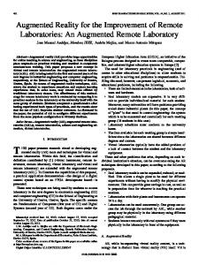
Fig. 6. Screenshot of the GUI of the dc motor EJS applet.
when available, the routing information for the TCP/IP camera pointed at each plant, which is used by the EJS applet to show actual images of the system being controlled. The EJS applets, provided to the students through the course Web page along with an applet user manual and a description of the objectives of all the experiments, let the student change the parameter values of the PLC program and observe the evolution of some of its variables. The two applets share the same view (GUI and user calls to the EJS applet-server communication library) and model (periodic calls to the EJS applet-server communication library), differing only in the experiment name that is initially sent to the server. The GUI of these EJS applets is pictured in Fig. 6, where the elements that interact with the PLC are shown in the top half of the screen, and the evolution of the variables and the images gathered by the IP camera are shown in the bottom half of the screen. The elements at the top left let the students save the evolution information in a file, select the EJS applet visualization period, establish the connection between the EJS applet and the server, send the run/stop/reset/disconnect PLC orders to the server, and select the window time of the evolution variables. The elements in the center are used to display or select the type of reference signal (sinusoidal, square, triangular, or external) and the properties (period, amplitude, and offset) of the internal signals. The elements at the right are used to display or select the type of controller (ESF, 2-DOF, PID, or manual), the control sampling time (T) and the properties of each controller, organized under its corresponding tab (Fig. 6 shows the matrix and vectorial parameters of the ESF controller). The selected reference and control properties are only sent to the server, and therefore applied to the PLC that the server associates with the EJS applet, when the update button on the left is pressed, so the students can modify the values of multiple parameters in the EJS applet before actualizing the changed values in the PLC. In addition, the EJS applet periodically calls the function that reads the values of the PLC structure that stores the reference, control, and measurement signals, and represents their values against the time when those values are updated in the PLC. That is, the bottom curves show the actual time and
162
IEEE TRANSACTIONS ON EDUCATION, VOL. 56, NO. 2, MAY 2013
TABLE I STUDENTS SURVEY RESULTS
signal values of the PLC. Finally, the message area at the bottom left displays information related to the EJS connection status. C. Validating the UCM EJS-PLC Lab as an Educational Tool In order to evaluate the pedagogical benefits of using the UCM EJS-PLC lab, the feedback of two different groups of undergraduate students of the Control Systems course has been collected and analyzed. The first group consists of the students of the 2010–2011 academic year, who during that academic year did not have access to the UCM EJS-PLC Lab. Therefore they had to design the controllers and apply them to the plants, with the support of the teacher in charge of the hands-on lab, using the TwinCAT programming and run-time environment locally and directly. The second group consists of the students of the 2011–2012 academic year, who were able to run the experiments using the UCM EJS-PLC lab both remotely and in the hands-on lab sessions. Hence, the second group experienced the tool presented in this paper as an educational tool in the course; while the first group was recontacted one year later to test the tool voluntarily to provide feedback. The survey was conducted among the 7 students of the first group who were willing to try the tool and the 10 of the second group who were attending the course. Students were asked to respond to the questions7 presented in Table I on a range from 2 to 2, indicating strong disagreement ( 2), a neutral attitude (0), or strong agreement ( 2). The mean and standard deviations for each question (Q1–Q8) and group of students is shown in Fig. 7. The results clearly show that both groups of students had a positive experience using the UCM EJS-PLC lab, as only a few students answered the questions with a weak negative ( 1) or indifferent (0) answer. Moreover, the students of the first group are more positive about questions Q1–Q4, and the students of the second group are more positive about questions Q5–Q7. Thus, the first group of students have a higher appreciation for the freedom of preparing the experiments anywhere, the remote visualization of the images of the plant, and the impact that experimenting freely would have had on their understanding of the subject. This could be because they would have liked to have 7Both groups were asked questions Q1–Q7 (in the conditional tense for the first group). Only the first group responded to question Q8 because the second group has never seen the TwinCAT developing tools.
Fig. 7. Statistical analysis of the student survey results.
been able to use this tool in the academic year they took the Control System course, as their positive answer to Q8 corroborates. In contrast, those students who used the tool during a complete course show a higher interest in knowing what is behind the tool and in using it during the experiments and in other courses. This could be due to their higher familiarity with the tool, while their curiosity could have been aroused by their lack of knowledge of the complexity of the TwinCAT system that is hidden by the EJS applet front end. In addition to the survey, the students were also asked to provide any other type of feedback they considered relevant to improve or to use the tool. Only one student of the second group provided this type of feedback (suggesting improvements in the GUI of the applet), but almost all the students of the first group did. Their comments really show how much they believe that they would have benefited from preparing the experiments at home with the tool, and that they also want a hands-on laboratory season where the instructors, in person, explain in detail what the systems are doing. In other words, they seemed really concerned about the fact that the remote lab could be used as a substitute for, and not as a complement to, the hands-on lab. The teachers agree with this point of view, and thus they intend to use the tool to let the students prepare the work at home
BESADA-PORTAS et al.: REMOTE CONTROL LAB USING EJS APPLETS AND TwinCAT PROGRAMMABLE LOGIC CONTROLLERS
and to continue trying as many additional experiments as they want after a hands-on session. Moreover, taking into account the interest that the second group has shown in the tools used to develop the UCM EJS-PLC lab, the instructors are also planning to spend a final lab session to explain to the students how the TwinCAT PLC closes the real-time control loop over the selected plant and how the EJS applet lets them observe and modify the behavior of the PLC, and therefore the behavior of the plant. The lab can thus be used indirectly to introduce some topics that appear in advanced control courses with the purpose of motivating students to enroll in them. D. Possible Extensions of the UCM EJS-PLC Lab The successful results of the lab, supported by the enthusiasm of the course professors, is leading the authors to plan the development of some new control experiments that could be carried out remotely, using the strategy presented in this paper, for future courses. Moreover, as far as the input/output PLC signals applied to the plant are of the same type as those used to control the dc motor or reconfigurable circuit, the same EJS applet and PLC code can be used to control the new systems by reassigning, with the TwinCAT System Manager, the input/ouput PLC signals to other ports or card terminals. This philosophy can be applied to virtualize some of the experiments in speed and position control with the G36A transducer trainer by Elettronica Veneta [21] that the UCM already has. There are further plans to virtualize different types of controllers for the UCM vertical rotor system [22], which will require a PLC program that communicates with the motors and some ultrasonic sensors via the I2C protocol. Additionally, the possibility of executing multiple tasks and running several PLCs on the same PC means that multiple control systems could be connected, or that some tasks could be used to simulate the behavior of the system in the PLC to compare simulated and real experiments carried out in the PLCs. Furthermore, control experiments relying on multitasking elements, multirate or aperiodic event-based behaviors, or numerical controllers (NCs) and computing NCs (CNCs) processes can also be considered, thanks to the TwinCAT’s capability to handle these types of processes. IV. CONCLUSION This paper presents a new methodology to develop remote experiments for the control subjects of System Engineering and Automatica, based on the combined use of TwinCAT PLCs and EJS applets. The first elements are used to program the control task and run them in real time over a TwinCAT run-time system. The second are used to provide access to the parametrization and evolution variables of the PLCs, by means of different types of calls to an intermediate Java application. This intermediate application is in charge of managing the EJS-PLC access and of supporting the exchange of information between the EJS applets and the PLCs. The proposed methodology combines the EJS facilities to quickly develop interactive applets (that can run in any PC with the Java run-time) with the TwinCAT capabilities to develop and
163
deploy real-time controllers whose variables can be accessed, when required, from an external (and optionally remote) application. Hence, the teachers use the TwinCAT system to implement real-time controllers for different types of systems and EJS to quickly develop student-friendly applets to remotely access the information of the controllers. The intermediate application is required to access the PLCs from a properly configured PC (the server) and to avoid several students gaining simultaneous access to them. The paper also introduces, as an application example, the UCM remote EJS-TwinCAT control laboratory used in two undergraduate Control courses at the University Complutense of Madrid and validates the applicability of the approach based on student feedback. The plants and controllers developed so far show the potential of the methodology, which offers a great opportunity to develop new control experiments for different types of systems and controllers, exploiting all the possibilities (multitasking, multirate, aperiodicity, NC and CNC, etc.) that the underlying TwinCAT system offers. ACKNOWLEDGMENT The authors want to thank to D. Sanchez Foces and F. Marquez Vidal for their support in setting up the experiments in the labs. Additionally, they also want to thank all the students who completed the questionnaire, especially those of the 2010–2011 course who volunteered to provide the comparative information. REFERENCES [1] G. Chang, Z. Yeh, H. Chang, and S. Pan, “Teaching photonics laboratory using remote-control web technologies,” IEEE Trans. Educ., vol. 48, no. 4, pp. 642–651, Nov. 2005. [2] S. Sivakumar, W. Robertson, M. Artimy, and N. Aslam, “A Web-based remote interactive laboratory for internetworking education,” IEEE Trans. Educ., vol. 48, no. 4, pp. 586–598, Nov. 2005. [3] B. Alhalabi, D. Marcovitz, K. Hamza, and S. Hsu, “Remote labs: An innovative leap in the world of distance education,” in Proc. 5th IFAC Symp. Adv. Control Educ., 2000, pp. 1–6. [4] C. Gravier, J. Fayolle, B. Bayard, M. Ates, and J. Lardon, “State of the art about remote laboratories paradigms—Foundations of ongoing mutations,” Int. J. Online Eng., vol. 4, pp. 1–9, 2008. [5] R. Dormido, H. Vargas, N. Duro, J. Sanchez, S. Dormido-Canto, G. Farias, F. Esquembre, and R. Dormido, “Development of a Web-based control laboratory for automation technicians: The three-tank system,” IEEE Trans. Educ., vol. 51, no. 1, pp. 35–44, Feb. 2008. [6] M. Stefanovic, V. Cvijetkovic, M. Matijevic, and V. Simic, “A Labview-based remote laboratory experiments for control engineering education,” Comput. Appl. Eng. Educ., vol. 19, pp. 538–549, 2011. [7] M. Casini, D. Prattichizzo, and A. Vicino, “The automatic control telelab: A user-friendly interface for distance learning,” IEEE Trans. Educ., vol. 46, no. 2, pp. 252–257, May 2003. [8] A. Grau and Y. Bolea, The International Federation of Automatic Control, “Remote laboratory for control engineering degree,” in Proc. 17th World Congress, Seoul, Korea, 2008, pp. 13629–13633. [9] C. Lazar and S. Carari, “A remote-control engineering laboratory,” IEEE Trans. Ind. Electron., vol. 55, no. 6, pp. 2368–2375, Jun. 2008. [10] H. Vargas, J. Sanchez, N. Duro, R. Dormido, S. Dormido-Canto, G. Farias, and S. Dormido, “A systematic two-layer approach to develop web-based experimentation environments for control engineering education,” Intell. Autom. Soft Comput., vol. 14, pp. 505–524, 2008. [11] G. Farias, A. Cervin, K. Årzén, S. Dormido, and F. Esquembre, “Multitasking real-time control systems in Easy Java Simulations,” in Proc. 17th IFAC World Congress, 2008, pp. 1–6. [12] National Instruments Corporation, Austin, TX, “Labview Web page,” Accessed Jun. 1, 2012 [Online]. Available: http://www.ni. com/labview/ [13] Beckhoff Automation GmbH, Verl, Germany, “Beckhoff Web page,” Accessed Jun. 1, 2012 [Online]. Available: http://www.beckhoff.de/
164
IEEE TRANSACTIONS ON EDUCATION, VOL. 56, NO. 2, MAY 2013
[14] S. Dutta, S. Prakash, and D. Estrada, “A Web service and interface for remote electronic device characterization,” IEEE Trans. Educ., vol. 54, no. 4, pp. 646–651, Nov. 2011. [15] E. Besada-Portas, J. A. Lopez-Orozco, L. de la Torre, and J. M. de la Cruz, “EasyJava Simulations meets TwinCAT: Remote real-time control experiments using programmable logic controllers,” in Proc. 9th IFAC Symp. Adv. Control Educ., 2012, pp. 294–299. [16] Complutense University of Madrid, Madrid, Spain, “ISCAR laboratory Web page,” Accessed Jun. 1, 2012 [Online]. Available: http://www. dacya.ucm.es/isalab [17] “EJS Web page,” Accessed Jun. 1, 2012 [Online]. Available: http:// www.um.es/fem/EjsWiki/ [18] F. Esquembre, “Easy Java Simulations: A software tool to create scientific simulations in Java,” Comput. Phys. Commun., vol. 156, no. 6, pp. 199–204, Jan. 2004. [19] K. J. Astrom and R. M. Murray, Feedback Systems: An Introduction for Scientists and Engineers. Princeton, NJ: Princeton Univ. Press, 2008. [20] B. Wittenmark, K. L. Astrom, and K. Arzen, “Computer control: An overview,” Instituto Tecnologico de Lund, Lund, Sweden, IFAC Professional Brief, 2002. [21] Elettronica Veneta, Motta di Livenza, Italy, “Elettronica Veneta Web page,” Accessed Jun. 1, 2012 [Online]. Available: http:// www.elettronicaveneta.com/education [22] D. Sánchez-Benítez, E. Besada-Portas, J. M. de la Cruz, and G. Pajares, “Vertical rotor for the implementation of control laws,” in Proc. 9th IFAC Symp. Adv. Control Educ., 2012, pp. 224–229.
Eva Besada-Portas was born in Madrid, Spain, in 1974. She received the M.Sc. degree in physics and Ph.D. degree in computer engineering from the Complutense University of Madrid (UCM), Madrid, Spain, in 1997 and 2004, respectively. She has been an Assistant Professor with the Department of Computer Architecture and Automatic Control, UCM, since 2005. She was also a Post-doctoral Visiting Researcher with the Department of Computer Science, University of New Mexico, Albuquerque, from 2006 to 2010. Her research interests are in optimal control, evolutionary algorithms, UAVs, multisensor fusion systems, and machine learning techniques.
José A. Lopez-Orozco (M’02) received the M.Sc. and Ph.D. degrees in physics from the Complutense University of Madrid (UCM), Madrid, Spain, in 1991 and 1999, respectively. In 1992, he joined the Department of Computer Architecture and Automatic Control, UCM, as a Teaching Assistant and later as an Assistant Professor. Since 2002, he has been an Associate Professor. His current research interests include applications of automatic control, artificial neural networks, robotics, and multisensor fusion systems.
Luis de la Torre received the M.Sc. degree in physics, with specialization in electronic devices and automatic control, from the Complutense University of Madrid (UCM), Madrid, Spain, in 2008. He is an Assistant Professor with the Department of Computer Sciences Automatic and Control, UNED (Open University of Spain), Madrid, Spain, where he began the Ph.D. degree in systems engineering and automatic control in 2008. He previously joined the Department of Computers Architecture and Automatic Control, Complutense University of Madrid (UCM), Madrid, Spain, as a Research Fellow in 2007, while he was finishing the M.Sc. degree. His research interests are in evolutionary algorithms, UAVs, path planning, remote and virtual laboratories, and distance education.
Jesus M. de la Cruz (M’80) received the M.Sc. and Ph.D. degrees in physics from the Complutense University of Madrid (UCM), Madrid, Spain, in 1979 and 1984, respectively. From 1985 to 1990, he held teaching appointments with the UCM and the Open University of Spain (UNED), Madrid, Spain. From 1990 to 1992, he was with the Department of Electronics, Cantabria University of Santander, Santander, Spain. In October 1992, he joined the Department of Computer Architecture and Automatic Control, UCM, where he was the Dean from 1997 to 2001 and is currently a Full Professor and the Head of the Automatic Control and Robotics Group. His current research interests include broad aspects of automatic control and its applications, real-time control, optimization, statistical learning, and robotics. Dr. de la Cruz has been the Chair of the Spanish Chapter of the IEEE Oceanic Engineering Society.