Finally, I would like to thank my girlfriend Patricia Maldonado, without your love ...... Hodneland, E., Hanson, E., Munthe-Kaas, A. Z., Lundervold, A. & Nordbotten, ...
Implementation of an MPFA/MPSA-FV Solver for the Unsaturated Flow in Deformable Porous Media MASTER’S THESIS IN APPLIED AND COMPUTATIONAL MATHEMATICS
JHABRIEL VARELA
Department of Mathematics University of Bergen
May, 2018
Acknowledgments Foremost, I would like to thank my family for the unconditional support I have received throughout these years.
There are no words to express my gratefulness towards my supervisors: Jan Martin Nordbotten, Eirik Keilevgalen, and Sarah Gasda, who relentlessly and patiently guided me through my Master’s research. I must acknowledge the generous financial support of the National Postgraduate Scholarships Program: Carlos Antonio L´ opez (BeCAL); this thesis would not have been possible without the grant they gratified me. I would also like to thank my former supervisors Juan Pablo Nogues and Christian Schaerer for introduced me to the field of flow in porous media and encouraged me to pursue a postgraduate program. On a more personal note, I would like to thank all my friends in Paraguay that despite the distance inspired me to keep going ahead. Also, I was fortunate getting my new family at the Fantoft Student Hostel, where countless dinners and parties had taken place. Many of them, will be hard to forget. Finally, I would like to thank my girlfriend Patricia Maldonado, without your love, patient and support it would not have been possible to get to the finish line.
Jhabriel Varela May, 2018
iii
Abstract The Unsaturated Flow In Deformable Porous Media (UFIDPM) plays a crucial role in several academic and industrial applications such as; cracks induced by desiccation, collapsing soils, ground movement involving expansive soils, lateral earth surfaces, stability of vertical excavations, natural slopes subjected to environmental changes, construction and operation of a dam, etc. Typically, studying these systems with experimental techniques is impractical. On the other hand, numerical simulations allow us to investigate several scenarios in a short time and with reduced costs. At the moment, only Finite Element Method (FEM) based codes were available. FEM often shows conservative issues and when is applied to UFIDPM instabilities in the limit of incompressibility have been reported. Due to this issues, we were motivated to develop the first Cell Centered Finite Volume Method (CCFVM) based code for solving UFIDPM. The governing equations are derived following the extended Biot’s theory of three-dimensional consolidation which results in a coupled hydro-mechanical system. For the flow problem, we use the Richards’ equation whereas the mechanical problem is modeled using the linear elasticity equations. For the spatial discretization, we use multi-points approximations schemes. Specifically, Multi Point Flux Approximation (MPFA) for the flow problem and Multi Point Stress Approximation (MPSA) for the mechanical problem. Moreover, the time discretization of the equations was obtained using Backward Euler (BE). The code was implemented in MATLAB R2017b were two core toolboxes (MRST and FV-BIOT) were used. The resulting non-linear set of equations was solved using the Newton method together with Automatic Differentiation (AD). To test the capability of the code several sub-problems were validated. Furthermore, we present a numerical application where we focus on the desiccation process of a clayey soil in a Petri-dish. In this experiment, the water content reduction is caused by instantaneous water evaporation controlled by atmospheric conditions. Finally, by carefully post-processing the resulting stress field, the zones of tensile stress concentration, which corresponds to the areas where cracks are more likely to initiate, are identified.
iv
Contents Page Acknowledgments . . . . . . . . . . . . . . . . . . . . . . . . . . . . . . . . . . . . . . . . . . . .
iii
Abstract . . . . . . . . . . . . . . . . . . . . . . . . . . . . . . . . . . . . . . . . . . . . . . . . . .
iv
Contents . . . . . . . . . . . . . . . . . . . . . . . . . . . . . . . . . . . . . . . . . . . . . . . . . .
v
List of Figures . . . . . . . . . . . . . . . . . . . . . . . . . . . . . . . . . . . . . . . . . . . . . . vii List of Tables . . . . . . . . . . . . . . . . . . . . . . . . . . . . . . . . . . . . . . . . . . . . . . .
ix
Chapter 1: Introduction . . . . . . . . . . . . . . . . . . . . . . . . . . . . . . . . . . . . . . . .
1
. . . . . . . . . . . . . . . . . . . . . . . . . . . . . . . . .
3
Chapter 2: Fundamental concepts 2.1
2.2
2.3
Concepts of unsaturated flow in porous media
. . . . . . . . . . . . . . . . . . . . . . . .
4
2.1.1
Porosity . . . . . . . . . . . . . . . . . . . . . . . . . . . . . . . . . . . . . . . . . .
4
2.1.2
Representative elementary volume (REV) . . . . . . . . . . . . . . . . . . . . . . .
4
2.1.3
Saturation and water content . . . . . . . . . . . . . . . . . . . . . . . . . . . . . .
4
2.1.4
Hydraulic head and fluid potential . . . . . . . . . . . . . . . . . . . . . . . . . . .
5
2.1.5
Relative velocity . . . . . . . . . . . . . . . . . . . . . . . . . . . . . . . . . . . . .
6
2.1.6
Darcy’s law . . . . . . . . . . . . . . . . . . . . . . . . . . . . . . . . . . . . . . . .
6
2.1.7
The unsaturated zone . . . . . . . . . . . . . . . . . . . . . . . . . . . . . . . . . .
7
2.1.8
The Richards’ assumption
8
. . . . . . . . . . . . . . . . . . . . . . . . . . . . . . .
Concepts of linear elasticity . . . . . . . . . . . . . . . . . . . . . . . . . . . . . . . . . . .
8
2.2.1
Normal and shear stresses . . . . . . . . . . . . . . . . . . . . . . . . . . . . . . . .
9
2.2.2
Stress tensor . . . . . . . . . . . . . . . . . . . . . . . . . . . . . . . . . . . . . . .
10
2.2.3
Traction vector
11
2.2.4
Deformation, displacement and strain . . . . . . . . . . . . . . . . . . . . . . . . .
12
2.2.5
Uniaxial and shear Hooke’s law . . . . . . . . . . . . . . . . . . . . . . . . . . . . .
16
2.2.6
Poisson’s ratio . . . . . . . . . . . . . . . . . . . . . . . . . . . . . . . . . . . . . .
17
2.2.7 2.2.8
Generalized Hooke’s law . . . . . . . . . . . . . . . . . . . . . . . . . . . . . . . . . Plane stress and plane strain . . . . . . . . . . . . . . . . . . . . . . . . . . . . . .
18 21
2.2.9
Relations among elastic constants
. . . . . . . . . . . . . . . . . . . . . . . . . . .
21
Concepts of linear poroelasticity for saturated and unsaturated systems . . . . . . . . . .
23
. . . . . . . . . . . . . . . . . . . . . . . . . . . . . . . . . . . . .
2.3.1
Pore pressure . . . . . . . . . . . . . . . . . . . . . . . . . . . . . . . . . . . . . . .
23
2.3.2
The principle of effective stress and the Biot’s coefficient
. . . . . . . . . . . . . .
23
2.3.3
The principle of effective stress for unsaturated systems . . . . . . . . . . . . . . .
24
Chapter 3: Mathematical models and governing equations . . . . . . . . . . . . . . . . . .
26
3.1
3.2
Equations for unsaturated flow in non-deformable porous media
. . . . . . . . . . . . . .
27
. . . . . . . . . . . . . . . . . . . . . . . . . . . . . . . . .
27
3.1.1
Mass balance equation
3.1.2
The Richard’s equation and its different formulations . . . . . . . . . . . . . . . . .
28
3.1.3
Water retention curves . . . . . . . . . . . . . . . . . . . . . . . . . . . . . . . . . .
29
Equations of linear elasticity
. . . . . . . . . . . . . . . . . . . . . . . . . . . . . . . . . .
31
3.2.1
Local equilibrium equations . . . . . . . . . . . . . . . . . . . . . . . . . . . . . . .
31
3.2.2
The complete set of equations
33
. . . . . . . . . . . . . . . . . . . . . . . . . . . . .
v
3.3
3.4
Equations of saturated flow in deformable porous media . . . . . . . . . . . . . . . . . . .
34
3.3.1
Linear momentum balance equation . . . . . . . . . . . . . . . . . . . . . . . . . .
34
3.3.2
Mass conservation . . . . . . . . . . . . . . . . . . . . . . . . . . . . . . . . . . . .
35
3.3.3
The complete set of equations . . . . . . . . . . . . . . . . . . . . . . . . . . . . . .
39
. . . . . . . . . . . . . . . . .
40
3.4.1
Linear momentum balance equation . . . . . . . . . . . . . . . . . . . . . . . . . .
40
3.4.2
Mass conservation . . . . . . . . . . . . . . . . . . . . . . . . . . . . . . . . . . . .
40
3.4.3
The complete set of equations . . . . . . . . . . . . . . . . . . . . . . . . . . . . . .
43
Boundary and initial conditions . . . . . . . . . . . . . . . . . . . . . . . . . . . . . . . . .
44
. . . . . . . . . . . . . . . . . . . . . . . . .
46
4.1
Multi Point Flux Approximation . . . . . . . . . . . . . . . . . . . . . . . . . . . . . . . .
46
4.2
Multi Point Stress Approximation . . . . . . . . . . . . . . . . . . . . . . . . . . . . . . .
51
4.3
Discrete representation of continuous variables . . . . . . . . . . . . . . . . . . . . . . . .
53
4.4
Discrete MPFA/MPSA operators
54
4.5
Discretization of the mathematical models . . . . . . . . . . . . . . . . . . . . . . . . . . .
55
4.5.1
The discrete equations for the unsaturated flow in non-deformable porous media .
56
4.5.2
The discrete equations of linear elasticity . . . . . . . . . . . . . . . . . . . . . . .
60
4.5.3
The discrete equations for the saturated flow in deformable porous media . . . . .
61
4.5.4
The discrete equations for the unsaturated flow in deformable porous media . . . .
64
4.6
Solving the system of equations . . . . . . . . . . . . . . . . . . . . . . . . . . . . . . . . .
67
4.7
Computational implementation . . . . . . . . . . . . . . . . . . . . . . . . . . . . . . . . .
68
3.5
Equations of unsaturated flow in deformable porous media
Chapter 4: Discretization and implementation
. . . . . . . . . . . . . . . . . . . . . . . . . . . . . . .
4.7.1
General implementation framework . . . . . . . . . . . . . . . . . . . . . . . . . . .
69
4.7.2
A simulator based on Automatic Differentiation . . . . . . . . . . . . . . . . . . . .
69
Chapter 5: Numerical validations and demonstrations . . . . . . . . . . . . . . . . . . . . .
75
5.1
5.2
Unsaturated flow in non-deformable porous media . . . . . . . . . . . . . . . . . . . . . .
76
5.1.1
Case 1: One-dimensional unsaturated water infiltration . . . . . . . . . . . . . . .
76
5.1.2
Case 2: Three-dimensional simulation for a heterogeneous porous media . . . . . .
80
Linear Elasticity . . . . . . . . . . . . . . . . . . . . . . . . . . . . . . . . . . . . . . . . .
83
5.2.1
Case 3: Horizontal compression under the plane stress assumption. . . . . . . . . .
83
5.2.2
Case 4: Compression in an extruded hexagonal grid. . . . . . . . . . . . . . . . . .
86
Saturated flow in deformable porous media . . . . . . . . . . . . . . . . . . . . . . . . . .
88
5.3.1
Case 5: Terzaghi’s consolidation problem . . . . . . . . . . . . . . . . . . . . . . .
88
5.3.2
Case 6: Three-dimensional consolidation in a heterogeneous porous media . . . . .
92
Chapter 6: Numerical application . . . . . . . . . . . . . . . . . . . . . . . . . . . . . . . . . .
96
5.3
Chapter 7: Conclusion . . . . . . . . . . . . . . . . . . . . . . . . . . . . . . . . . . . . . . . . . 106 Appendices . . . . . . . . . . . . . . . . . . . . . . . . . . . . . . . . . . . . . . . . . . . . . . . . 107 Bibliography . . . . . . . . . . . . . . . . . . . . . . . . . . . . . . . . . . . . . . . . . . . . . . . 111
vi
List of Figures Page 2.1
Representative elementary volume . . . . . . . . . . . . . . . . . . . . . . . . . . . . . . .
5
2.2
Hydraulic, pressure and elevation heads for a laboratory manometer. . . . . . . . . . . . .
6
2.3
The unsaturated system at macro and pore scale. . . . . . . . . . . . . . . . . . . . . . . .
7
2.4
Normal stress acting on a point.
. . . . . . . . . . . . . . . . . . . . . . . . . . . . . . . .
9
2.5
Shear stress acting on a point. . . . . . . . . . . . . . . . . . . . . . . . . . . . . . . . . . .
10
2.6
Stresses acting on a three-dimensional volume element. . . . . . . . . . . . . . . . . . . . .
10
2.7
Traction vector acting on a wedge. . . . . . . . . . . . . . . . . . . . . . . . . . . . . . . .
11
2.8
Elongation of a bar under applied tensile forces at both ends . . . . . . . . . . . . . . . .
13
2.9
Elongation of bar represented as two-half bars in series . . . . . . . . . . . . . . . . . . . .
13
2.10 An elastic body before and after some deformation in the x − y plane . . . . . . . . . . .
14
2.11 Possible deformations in a linear elastic body. . . . . . . . . . . . . . . . . . . . . . . . . .
15
2.12 Axially loaded bar. . . . . . . . . . . . . . . . . . . . . . . . . . . . . . . . . . . . . . . . .
17
2.13 Diagram of an isotropic linear elastic material with Poisson ratio of 0.5 subject to axial forces along the x-axis only. . . . . . . . . . . . . . . . . . . . . . . . . . . . . . . . . . . .
18
3.1
Water retention curves . . . . . . . . . . . . . . . . . . . . . . . . . . . . . . . . . . . . . .
30
3.2
Free-body diagram for an infinitesimal rectangular parallelepiped with its origin in (¯ x, y¯, z¯) 31
4.1
TPFA vs MPFA . . . . . . . . . . . . . . . . . . . . . . . . . . . . . . . . . . . . . . . . .
47
4.2
Dual grid in the context of MPFA. . . . . . . . . . . . . . . . . . . . . . . . . . . . . . . .
48
4.3
Cell center x0 and continuity points x ¯1 , x ¯2 . . . . . . . . . . . . . . . . . . . . . . . . . . .
48
4.4
Two-dimensional interaction regions. . . . . . . . . . . . . . . . . . . . . . . . . . . . . . .
49
4.5
Schematic representation of the Newton method applied to a generic non-linear equation.
68
4.6
General implementation framework. . . . . . . . . . . . . . . . . . . . . . . . . . . . . . .
69
5.1 5.2
Case 1: Computational grid . . . . . . . . . . . . . . . . . . . . . . . . . . . . . . . . . . . Case 1: Pressure head and water content profiles . . . . . . . . . . . . . . . . . . . . . . .
76 78
5.3
Case 1: Number of iterations and cumulative CPU time . . . . . . . . . . . . . . . . . . .
78
5.4
Case 1: Numerical convergence analysis. . . . . . . . . . . . . . . . . . . . . . . . . . . . .
79
5.5
Case 2: Computational grid and permeability field. . . . . . . . . . . . . . . . . . . . . . .
80
5.6
Case 2: Number of iterations and CPU time . . . . . . . . . . . . . . . . . . . . . . . . . .
81
5.7
Case 2: Water Content for several time steps. . . . . . . . . . . . . . . . . . . . . . . . . .
82
5.8
Case 3: Computational grid . . . . . . . . . . . . . . . . . . . . . . . . . . . . . . . . . . .
84
5.9
Case 3: Displacement fields for a horizontal compression in a two-dimensional elastic body
85
5.10 Case 4: Absolute errors ex and ey for the horizontal and vertical displacements. . . . . . .
85
5.11 Case 4: Computational grid . . . . . . . . . . . . . . . . . . . . . . . . . . . . . . . . . . .
86
5.12 Case 4: Displacement field for a horizontal compression of a three-dimensional elastic body in an extruded hexagonal grid. . . . . . . . . . . . . . . . . . . . . . . . . . . . . . . . . .
87
5.13 Case 5: Computational grid . . . . . . . . . . . . . . . . . . . . . . . . . . . . . . . . . . .
89
5.14 Case 5: Validation of a one-dimensional consolidation problem . . . . . . . . . . . . . . .
91
5.15 Case 5: Numerical convergence test . . . . . . . . . . . . . . . . . . . . . . . . . . . . . . .
92
5.16 Case 6: Computational grid (left) and location of the marble layer (right) . . . . . . . . .
93
5.17 Case 6: Water pressure and vertical deformation for several time steps. . . . . . . . . . . .
94
6.1
Numerical application: Cracks induced by desiccation . . . . . . . . . . . . . . . . . . . .
96
6.2
Numerical application: Triangular Delauney grid generated with PDE-Toolbox (left) and hexagonal Voronoi grid generated with MRST (right). . . . . . . . . . . . . . . . . . . . .
vii
97
6.3
Numerical application: Extruded hexagonal three-dimensional grid resembling the actual geometry of a Petri-dish. . . . . . . . . . . . . . . . . . . . . . . . . . . . . . . . . . . . . .
97
6.4
Numerical application: Pressure head and saturation for several times. . . . . . . . . . . . 101
6.5
Numerical application: Top pressure head and water flux as a function of time. . . . . . . 102
6.6
Numerical application: Horizontal and vertical displacement fields at Depth = 1.5 mm for three different times. . . . . . . . . . . . . . . . . . . . . . . . . . . . . . . . . . . . . . . . 103
6.7
Numerical application: Displacement in the z−direction for the final simulation time at several depths of the Petri-dish. . . . . . . . . . . . . . . . . . . . . . . . . . . . . . . . . . 104
6.8
Numerical Application: von Mises stress field . . . . . . . . . . . . . . . . . . . . . . . . . 105
viii
List of Tables Page 2.1
Conversion formulas among elastic constants for isotropic linear materials.
. . . . . . . .
23
4.1
Definition of MPFA/MSFA operators
. . . . . . . . . . . . . . . . . . . . . . . . . . . . .
55
5.1
Case 1: Physical properties . . . . . . . . . . . . . . . . . . . . . . . . . . . . . . . . . . .
76
5.2
Case 1: Time and iteration parameters . . . . . . . . . . . . . . . . . . . . . . . . . . . . .
77
5.3
Case 1: Boundary and initial conditions . . . . . . . . . . . . . . . . . . . . . . . . . . . .
77
5.4
Case 3: Physical properties . . . . . . . . . . . . . . . . . . . . . . . . . . . . . . . . . . .
84
5.5
Case 3: Boundary and initial conditions. . . . . . . . . . . . . . . . . . . . . . . . . . . . .
84
5.6
Case 4: Boundary and initial conditions. . . . . . . . . . . . . . . . . . . . . . . . . . . . .
86
5.7
Case 5: Physical properties . . . . . . . . . . . . . . . . . . . . . . . . . . . . . . . . . . .
90
5.8
Case 5: Boundary and initial conditions . . . . . . . . . . . . . . . . . . . . . . . . . . . .
90
5.9
Case 5: Time and iteration parameters . . . . . . . . . . . . . . . . . . . . . . . . . . . . .
90
5.10 Case 6: Physical properties . . . . . . . . . . . . . . . . . . . . . . . . . . . . . . . . . . .
93
5.11 Case 6: Boundary and initial conditions. . . . . . . . . . . . . . . . . . . . . . . . . . . . .
93
6.1
Numerical application: Physical properties. . . . . . . . . . . . . . . . . . . . . . . . . . .
98
6.2
Numerical application: Boundary and initial conditions. . . . . . . . . . . . . . . . . . . . 100
6.3
Numerical application: Time and iteration parameters . . . . . . . . . . . . . . . . . . . . 100
ix
Chapter 1 Introduction In recent years, the interest in studying the unsaturated flow in deformable porous materials has increased considerably, primarily due to its broad range of application in hydro-geological systems. Within the most important applications we can mention: the determination of critical zones of crack formation in desiccating clayey soils, the construction and operation of dams, the stability analysis of vertical and near vertical excavations, the ground movement involving expansive soils, the consolidation of unsaturated soils, among several others (Fredlund & Rahardjo 1993). Numerical simulations allow us to study these type of systems in reasonable time spans and reduced attached costs, in contrast to laboratory experimentation. Therefore, there is an imperative need to count with robust, flexible and computationally-efficient codes. In this context, extensive research has been done in developing FEM-based solvers. Nevertheless, FEM intrinsically lacks conservative properties, and moreover, instabilities in the limit of solid incompressibility have been reported (Nagtegaal et al. 1974, Brezzi & Fortin 2012). In contrast to FEM, FVM shows an inherent conservative property whereas the same advantages are preserved, e.g. flexibility in representing complex domains. However, FVM-based codes for simulating the unsaturated flow in deformable porous media were not yet available. Motivated by filling this gap, in this thesis we present the first Cell Centered Finite Volume Method capable of simulating these type of systems. The governing equations for the unsaturated flow in deformable porous media are derived following the extended Biot’s theory of three-dimensional consolidation (Lewis & Schrefler 1998), which results in a coupled hydro-mechanical system. Instead of using a full two-phase formulation to model the flow problem, we use the Richards’ assumption of inviscid air where only the water motion is taken into account. On the other hand, the mechanical responses are described using the linear elasticity equations. As we already mentioned, the spatial discretization of the resulting governing equations is made using a cell-centered finite volume scheme. In particular, for the flow problem, we use Multi Point Flux Approximation (MPFA), whereas the linear elastic problem is discretized using Multi Point Stress Approximation (MPSA). Moreover, for the time discretization, we use Backward Euler. The code is implemented in Matlab R2017b where we use two core toolboxes: Matlab Reservoir Simulation Toolbox (MRST) and FV-Biot. MRST provides the basic data structure, mesh generation capabilities and Automatic Differentiation (AD) that is being used together with the Newton method to solve the resulting non-linear set of discrete equations. Besides, FV-Biot provides the MPFA/MPSA discretization and the coupling terms to solve the unsaturated poroelastic system. 1
2
From a modeling standpoint, this thesis is divided into four parts, i.e., the unsaturated flow in nondeformable porous media (Richards’ equation), the linear elasticity equations (Navier-Lam´e equations), the saturated flow in deformable porous media (Biot equations) and the unsaturated flow in deformable porous medium. The primary purpose of structuring the thesis this way is to present the concepts, governing equations and discretization procedure in increasing order of complexity until we arrive at the final model, which in turn, can be seen as a generalization of the previous three parts. In the following, we present a summary of the chapters covered in this thesis
Chapter 2: covers the fundamental concepts of the flow in unsaturated porous media, the linear elastic behavior of solid bodies and the saturated/unsaturated linear poromechanics. Chapter 3: focuses on the derivation of the governing equations for each of the four parts of the thesis, using the concepts introduced in Chapter 2. Chapter 4: deals with the discretization and implementation aspects. We start giving a brief description of the MPFA and MPSA techniques. Then, the computational vectorial representation of the state variables and the MPFA/MPSA discrete operators are introduced. Finally, the set of discretized equations are derived in details using the governing equations from Chapter 3. In regard to the implementation aspects, we present the general implementation framework and explain the iterativebased scheme for solving the non-linear set of equations. We conclude the chapter introducing a simulator based on Automatic Differentiation for solving the Richards’ equation. Chapter 5: concentrates in the numerical validations and demonstrations of the first three parts of the thesis. Chapter 5 is subdivided into three parts, in each part one numerical validation and one numerical demonstration is covered. Chapter 6: focuses on a numerical application of the unsaturated flow in deformable porous media. In this numerical application, we simulate the desiccation process of clayey soil in a Petri-dish. The primary motivation to study desiccation in clayey soils is the formation of cracks, which are often seen in mudcracks. The desiccation process is driven by instantaneous evaporation of water at the surface of the Petri-dish, which in turn, depends on the atmospheric conditions. Moreover, we are particularly interested in the mechanical responses within the domain, i.e., resulting displacement and stress fields. By carefully post-processing the stress field, we can identify the zones of tensile stress concentration, and consequently infer the areas where cracks are more likely to initiate. Chapter 7: establishes the conclusions of this thesis. Also, we propose further investigations based on the results achieved in this work.
Even though this thesis has been focused on hydro-geological systems, with some modifications, applications from other fields can be studied. For example, biological systems such as tissues (Hodneland et al. 2016) and bones (Giorgio et al. 2016) have been investigated using the Biot equations.
Chapter 2 Fundamental concepts In this chapter, we present the fundamental concepts that later will be needed to derive the equations that govern the problems considered on each part of this thesis. This chapter aims to provide the essential information related to the flow and linear elasticity problems. One of the challenges of writing this thesis was to develop a unified (and unique) nomenclature system without moving too far away from the standard nomenclature found in the literature. The chapter is divided as follows. In section 2.1 we present the fundamental concepts related to the flow in porous media. Several concepts such as porosity, REV, saturation and water content, potentials, relative velocity and Darcy’s law are formally introduced. Moreover, we pay particular attention to the unsaturated system and present the Richards’ assumption, which will be crucial for the derivation of the mathematical models. The fundamental concepts of linear elasticity are presented in section 2.2. In this section, we introduce concepts such as normal and shear stresses, the stress tensor, the traction vector, the relations between deformation, displacement and strain, the Hooke’s law and the Poisson ratio. Moreover, we cover the plane stress and plane strain assumptions while remarking their scope of validity. Finally, we present other important elastic constants often found in the literature and the relations among them. Lastly, in section 2.3 we focus on the fundamental concepts of linear poroelasticity for both, saturated and unsaturated systems. We start by introducing the concept of pore pressure. Then, we state the principle of effective stress while presenting the Biot’s coefficient. Finally, using the Richards’ assumption, we extend the principle of effective stress to unsaturated systems.
3
2.1
Concepts of unsaturated flow in porous media
2.1
4
Concepts of unsaturated flow in porous media
In this section, we present the concepts of the unsaturated flow in porous media. We start by introducing basic concepts such porosity, representative elementary volume, and saturation. Then, we focus on the different types of potentials that rule the flow of fluids in porous media, i.e., hydraulic, pressure and elevation potentials. We proceed by defining the concept of relative velocity, which later will be of remark importance for the derivation of the mass conservation equations. Coming up next is the multiphase version of Darcy’s law, which gives a quantitative measure of the water velocity as a function of its driven forces. Finally, we describe the unsaturated zone on the pore and macro scales and introduce the Richards’ assumption.
2.1.1
Porosity
The fundamental property that defines a porous media is the porosity. The porosity n is defined as the ratio between the void space (space occupied by the fluids) Vf and the total volume of the porous medium V , which is equivalent to the sum of the void space and the volume occupied by the solid grains Vs (Pinder & Celia 2006) n=
2.1.2
Vf Vf = . V Vs + Vf
(2.1)
Representative elementary volume (REV)
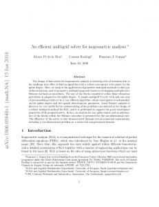
The representative elementary volume (REV) is a concept used to describe the fluid flow in porous media. Applying volume averaging techniques the micro-scale properties of a porous media can be represented at a larger scale by introducing new properties. In essence, the REV should be sufficiently large to avoid fluctuations of the averaged properties but small enough to represent the spatial dependence of such properties (Dietrich et al. 2005). A schematic representation of the concept of REV and its dependency on a generic property, i.e porosity is shown in Fig. 2.1.
2.1.3
Saturation and water content
Whenever more than one fluid phase is filling the void space, we have a multiphase system, i.e., water and air. If this is the case, it is common to use the concept of saturation (or degree of saturation). The saturation of water is given as the ratio between the pore space which is occupied by water and the total pore volume in a representative elementary volume (REV) (Lewis & Schrefler 1998, Bear 2013, Bachmat & Bear 1987). Hence, we have Sw =
Vw Vw = , Vf Vw + Va
(2.2)
2.1
Concepts of unsaturated flow in porous media
5
Figure 2.1 Representative elementary volume. Borrowed from Flow and Transport in Fractured Porous Media by Peter Dietrich et al, p. 27. where Vw and Va are the volumes of water and air. Naturally, we could also define the saturation of air Sa =
Va Va = . Vf Vw + Va
(2.3)
It should be evident that both saturation must add to one, i.e., Sw + Sa = 1. In soil mechanics and hydrogeology, the concept of water content (or moisture content) is often preferred over the saturation. The water content θw is defined as the product between the saturation of water and the porosity (Pinder & Gray 2008) θw = nSw .
(2.4)
Note that the water content represents the amount of water contained in a porous material and is bounded between 0 and n.
2.1.4
Hydraulic head and fluid potential
Hubbert (1940) in his famous article The theory of ground-water motion defines potential as “a physical quantity, capable of measurement at every point in a flow system, whose properties are such that flow always occurs from regions in which the quantity has higher values to those in which it has lower, regardless of the direction in space” (p. 794). The concept of potential is crucial to the understanding of fluid flow in porous media, specially when we are dealing with gravity contributions. A detailed explanation of these concepts are beyond the scope of this thesis. However, we referred to (Freeze & Cherry 1979) for an excellent introduction.
In groundwater hydrology, it is common to work in gage pressures, i.e., setting the atmospheric pressure
2.1
Concepts of unsaturated flow in porous media
6
equal to zero. Whenever this is the case, we can define the water potential Φw as φw =
pw + gζ, ρw
(2.5)
where pw is the water pressure, ρw is the water density, g is the modulus of the gravity acceleration
1
,
and ζ is the elevation head, i.e. the height from a reference point to the measurement point (Freeze & Cherry 1979).
If we divide Eq. (2.5) by g we have hw =
pw + ζ = ψw + ζ, ρw g
(2.6)
where hw is the hydraulic head and ψw the pressure head of the water (Freeze & Cherry 1979). These concepts are schematically depicted for a laboratory manometer in Fig. 2.2.
P h ⇣
⇣=0 Figure 2.2 Hydraulic head h, pressure head ψ, and elevation head ζ for a laboratory manometer. Adapted from Groundwater by R. Allan Freeze and John A. Cherry, p. 20.
2.1.5
Relative velocity
Throughout this thesis, a material coordinate system is employed for the solid phase and a spatial coordinate system for the fluid phases, following the classical continuum mechanics approach (Lewis & Schrefler 1998). In addition, we always consider isothermal equilibrium and negligible inertial forces. Due to the convenient choice of reference systems, the water velocity can be referred to the solid phase using the relative velocity vws = vw − vs .
2.1.6
(2.7)
Darcy’s law
For a non-deformable saturated porous media, the momentum conservation is often stated in the form of the Darcy’s law (Darcy 1856). This law suggests a linear relationship between the fluid velocity and the 1 To
be precise, g = g . However, for simplicity we avoid the formal notation.
2.1
Concepts of unsaturated flow in porous media
7
gradients in pressure and/or elevation (Chen et al. 2006). However, to account for the simultaneous flow of two or more fluid phases, we must use the extended multiphase version of the Darcy’s law qw = nSw vws = −k
� krw ∇pw − ρw g , µw
(2.8)
where qw is the Darcy’s water velocity (often called specific discharge), k is the intrinsic permeability of the medium, generally a second order tensor dependent only on the porous medium (Freeze & Cherry 1979). The relative permeability krw is included to account for the simultaneous flow and it is often modeled as a function of the water saturation (Chen et al. 2006). The viscosity is represented by µw and g is the gravity acceleration, considered positive downwards (Lewis & Schrefler 1998).
In subsurface hydrology, it is common to express Darcy’s law in terms of the hydraulic head and the w hydraulic conductivity Ksat = kρw g/µw w qw = −Ksat krw ∇hw .
(2.9)
w Some authors, recognize the product Ksat krw as the unsaturated hydraulic conductivity Kw . Note that,
both, the saturated and unsaturated hydraulic conductivity now depend not only on the properties of the porous media but the properties of the fluid as well (Pinder & Celia 2006).
2.1.7
The unsaturated zone
Groundwater is often extracted from aquifers, where all the available pore space is filled with water. Nevertheless, there are certain zones where water and air coexist, those zones are referred as unsaturated (or vadose) zones (see Fig. 2.3a). Unlike the saturated zone, unsaturated systems are characterized by additional boundaries, which separates the different phases, i.e., water, air, and solid grains. A schematic representation of such system can be seen in Fig. 2.3b (Pinder & Celia 2006). For a fairly extensive introduction to aquifers and its respective zones, we referred to (Bear 2013).
Air Water
Grains
(a)
(b)
Figure 2.3 a) Cross-section of a hillslope depicting the vadose zone, capillary fringe, water table, and phreatic or saturated zone. Borrowed from United States Geological Survey. b) Schematic representation of a unsaturated system at the pore scale. Adapted from Subsurface Hydrology by George F. Pinder and Michael A. Celia, p. 405.
2.2
Concepts of linear elasticity
8
The unsaturated zone is relevant for several reasons, such as: transmission of water from the atmosphere to the saturated zone via infiltration or precipitation, the support of almost all kinds of plants and the active return of water from the subsurface to the atmosphere, just to mention a few of them (Pinder & Celia 2006). Among the current fields of research we can cite: colloid and colloid-facilitated transport, biogeochemical transport, multiphase flow and remediation, non-equilibrium and preferential flow, ˇ unek agricultural applications, constructed wetlands and inverse problems (Sim ˙ & Bradford 2008).
2.1.8
The Richards’ assumption
To adequately describe the simultaneous flow of water and air in a non-deformable porous media, we must use the well known two-phase flow equations (Chen et al. 2006). However, the disparity in physical properties between the water and air allow us to make some simplifications. Generally speaking, the air can be considered three orders of magnitude less dense than water, and two orders of magnitude less viscous. As the flow in a porous media is inversely proportional to the viscosity of the fluid, to obtain the same flow, the air needs a pressure gradient 100 times smaller than the water (Pinder & Gray 2008). Thus, we can assume that the air is inviscid with respect to the water. This simplification is often referred as the Richards’ assumption, first proposed by Richards (1931). We must emphasize that the Richards’ assumption does not imply a static air phase. On the contrary, it is infinitely mobile and can move without any significant gradients.
2.2
Concepts of linear elasticity
All types of materials describe at some extent elastic properties, i.e., if the application of external forces producing some structural deformation cease, the material restores its original configuration. In this section, we present the fundamental concepts that describe the elastic responses of a perfect solid body, i.e., the body recovers its identical original shape after the external sources of deformation disappear (Timoshenko & Goodier 1951). We start by introducing the two possible types of stresses, normal and shear. Then, we formally defined the stress tensor. A concept which is closely related to the stress, the traction vector is presented later. The next concepts cover the relationship between the deformation, displacement, and strain. After that, the link between stresses and strains is introduced progressively. We start by studying the uniaxial and shear versions of the Hooke’s law and then extend them to derive the general stress-strain relationships for a three-dimensional isotropic elastic body. We also cover the particular cases where either stresses or strains can be neglected in a specific direction, giving place to the well-known plane stress and plane strain states. Finally, we present other important elastic constants and a table where these constants are related one another.
2.2
Concepts of linear elasticity
2.2.1
9
Normal and shear stresses
Perfect elastic bodies which are subject to external forces can be seen of as transmitting these forces from one point to another. The transmission of such forces generates internal forces, the magnitude, of these forces are characterized by the material stress. Generally speaking, we can differentiate two types of stresses, i.e., normal stress and shear stress (Lubliner & Papadopoulos 2016). To illustrate the concept of normal stress, let us consider a small region of area ∆A, with center at c as depicted in Fig 2.4a. Moreover, let r be a characteristic dimension of this region, so that the area will vanish when r approaches to zero. Finally, let ∆Fn be the total normal force acting in this region. The normal stress σn at the point c on the cross-sectional area A is defined as σn = lim
r→0
∆Fn . ∆A
(2.10)
An interesting way to interpret Eq. (2.10) is to see σn as the force per unit area acting on a small circular region as it shrinks to the point c. It is important to state that if ∆Fn is a pull force, then σn is called tensile stress. On the other hand, if ∆Fn is a push force, then σn is a compressive stress (Lubliner & Papadopoulos 2016). In Fig. 2.4b we show a normal stress field acting on the y − z plane whose resultant force is Fn .
z
r
c
Fn
Fn
A
x
n
A
y (a)
(b)
Figure 2.4 a) Force ∆Fn acting on a small region of area ∆A centered at point c on the cross section. b) Normal stress field σn (y, z) and its resultant Fn . Adapted from Introduction to solid mechanics by J. Lubliner and P. Papadopoulus, p. 157-158. To introduce the concept of shear stress, let us consider a shear force Fs acting on a planar cross-section of area A. Note that, we are representing the shear force as vector to reflect the fact that its direction is not specified, even though we know it is acting on the plane of cross-sectional area (see Fig. 2.5a). This is an essential difference with normal, where the direction is always known. The shear force Fs can be seen as the resultant of distributed forces per unit area acting at different points of the cross-section (Lubliner & Papadopoulos 2016). Again, we must remark that these forces do not necessarily have the same direction, as we can see in Fig. 2.5b.
2.2
Concepts of linear elasticity
10
Analogously to Eq. (2.10) we can define the shear stress σs at a point c of the cross-section as ∆Fs . r→0 ∆A
σs = lim
(2.11)
z
Fs
Fs
rc A x
A
y (a)
(b)
Figure 2.5 a) Force ∆Fs acting on a circular region of area ∆A centered at point c on the cross section. b) Stresses acting on a cross section with a resultant shear force Fs . Adapted from Introduction to solid mechanics by J. Lubliner and P. Papadopoulus, p. 163-164.
2.2.2
Stress tensor
So far, we have introduced the concepts of normal stress and shear stress, representing them on an arbitrary circular region. Let us now, properly identify the stresses that are acting on a volume element. For simplicity, we will consider a cube in Cartesian coordinates (see Fig. 2.6). It is assumed that the volume element is small enough so we can neglect any variations in the stresses to its extent. In Fig. 2.6 we show all the stresses acting on each positive faces of the cuboid. We can recognize both normal and shear stresses acting on each face. Note that two subscripts are necessary to fully describe each stress,2 the first subscript indicates the direction of the stress vector and the second subscript refers to the direction normal to the cross-section (Lubliner & Papadopoulos 2016). y
yz xz
y zz
x
(x, y, z) yy xy
z z
yx xx zx
zy
x Figure 2.6 Stresses acting on a three-dimensional volume element. 2 As a matter of fact, the normal stresses can be represented using only one subscript. Nevertheless, to avoid any inconsistency we are always going to use two subscripts.
2.2
Concepts of linear elasticity
11
It is important to notice that if no forces are acting on the interior of the element, the stresses on the negative faces are equal in magnitude but opposite in direction to the ones that we are showing, consequently it is said that the volume element is in force equilibrium (Lubliner & Papadopoulos 2016). We can conveniently express all the components of the stress using matrix notation to define the stress tensor
2.2.3
σxx σ = σyx
σxy
σxz
σyy
σyz .
σzx
σzy
σzz
(2.12)
Traction vector
To introduce the concept of traction vector and lay emphasis on the tensorial nature of the stress, let us consider a two-dimensional wedge in the x − z plane as shown in the Fig. 2.7. We assume that the size of the wedge is infinitesimal so we can neglect any body forces that may act in it. The area of the wedge is
dA, and a resultant force T dA is acting on the body. Note that there are both normal and shear forces acting on each leg of the wedge (Lubliner & Papadopoulos 2016). zz xz
dA sin(✓)
zx
x xx
dA cos(✓)
T dA
z
n
✓
Figure 2.7 Traction vector acting on a wedge. If this system is in force equilibrium, the forces acting on each spatial coordinate must sum to zero. That is Tx dA = σxx dA cos θ + σxz dA sin θ,
(2.13)
Ty dA = σzx dA cos θ + σzz dA sin θ.
(2.14)
2.2
Concepts of linear elasticity
12
Dividing Eqs. (2.13) and (2.14) by dA and noting that nx = cos θ and ny = sin θ we have Tx = σxx nx + σxz ny , Ty = σzx nx + σzz ny .
The last equations can be expressed conveniently in matrix form as (
Tx
)
Ty
=
" σxx
σxz
σyx
σzz
#( ) nx ny
.
This result can be generalized to a three-dimensional case with almost no effort by considering a tetrahedron instead of a planar wedge. Indeed, this generalization carries the name of Cauchy Tetrahedron after the famous French mathematician. In matrix form, the three-dimensional traction vector can be written as (Lubliner & Papadopoulos 2016) σxx Tx Ty = σyx Tz σzx
σxy σyy σzy
σxz nx σyz ny , nz σzz
or alternatively as T = σ · n.
(2.15)
Even though the components of the traction vector have the same units than the components of the stress, they are not stress components, since they lack a reference to the axes defined by the inclined plane (Lubliner & Papadopoulos 2016). Understanding the difference between traction vector and stress is crucial in elasticity and solid mechanics, especially while defining boundary conditions in numerical simulations.
2.2.4
Deformation, displacement and strain
Deformation can be defined as a change in the distances between material points which leads to changes in shape and/or size of a body. All materials undergo at least some deformation under the influence of forces. We can quantify the deformation of a solid relative to some reference frame by introducing the concept of strain (Lubliner & Papadopoulos 2016).
Perhaps, the easiest way to observe a deformation is by analyzing the elongation of an isotropic bar under the application of tensile forces acting at both ends as shown in Fig. 2.8 (Lubliner & Papadopoulos 2016). The relative stretch λ can be defined as λ=
L + ∆L ∆L =1+ . L L
(2.16)
2.2
Concepts of linear elasticity
13
L+
L
L
Figure 2.8 Elongation of a bar under applied tensile forces at both ends. Adapted from Introduction to solid mechanics by J. Lubliner and P. Papadopoulus, p. 215. Note that λ is always a positive number, if the body suffers an elongation λ > 0, if the body suffers a contraction λ < 0 and if the material is rigid λ = 1.
If we divide the bar under consideration in Fig. 2.8 into two identical half-bars, applying the same tensile force on each of them, we will see that each bar is stretched by ∆L/2 (see Fig. 2.9).
(L +
L)/2
(L +
L/2
L)/2
L/2
Figure 2.9 Elongation of bar represented as two-half bars in series. Adapted from Introduction to solid mechanics by J. Lubliner and P. Papadopoulus, p. 216. We could progressively subdivide the original bar from Fig. 2.8 into an arbitrary number of bars in series, where the elongation ∆L will be proportional to the respective bar length. However, the elongation per unit length ∆L/L is independent of the bar length (Lubliner & Papadopoulos 2016). This quantity is usually referred to as the longitudinal strain and denoted by εL εL =
∆L . L
(2.17)
If the bar lengthens εL > 0, if the bar shortens εL < 0 and if the bar is rigid εL = 0. Note that λ is easily related with �L by λ = 1 + εL .
(2.18)
Unfortunately, the definition of longitudinal strain is not unique. In fact, nothing stops us from defining the strain as the ratio between ∆L and the final length L0 = L + ∆L. To avoid confusions, let us define this strain as �L �L =
∆L εL = . L + ∆L 1 + εL
(2.19)
The important thing to remark here is that the difference between this two strains is small as long as the elongation ∆L is small relative to the original length L. In other words, if the strain satisfy |εL | 0.9}.
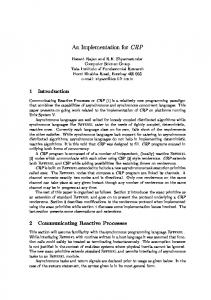
Until this point, our discussion was restricted to the spatial dependency of the tensile stress. However, the tensile stresses, and therefore the von Mises stresses, are time dependent. We will typically expect tensile stress to increment with time as soil shrinkage becomes more pronounced (Peron, Laloui, Hueckel & Hu 2009). This tendency is shown in Fig. 6.8 (left), where the maximum value of the von Mises stress within the domain as a function of time is plotted. Finally, we show the zones of concentrated normalized von Mises stress for the final simulation time in Fig. 6.8 (right), where the tensile stresses reached their maximum values. These zones correspond to the upper lateral walls of the Petri-dish. Thus, we can infer that cracks will initiate at the walls and propagate towards the interior of the domain. These results go in agreement with the experiments of (Groisman & Kaplan 1994). They have reported that primary cracks develop at the walls, mainly due to the high friction between the container and the porous material. The exact time of crack formation will primarily depend upon the tensile strength of the material under consideration. However, the exact location is quite difficult to determine. This will strongly depend upon the inhomogeneities of the material and possible nucleation points. The natural extension of this numerical application will be to simulate the crack initiation. Nevertheless, this requires the consideration of several modeling, and implementational aspects that are beyond the scope of this thesis. These aspects are mentioned as further investigations in the next chapter.
Figure 6.8 Left: Maximum von Mises stress as a function of time. Right: Zones of concentrated normalized von Mises stress located at the walls of the Petri-dish.
Chapter 7 Conclusion In this thesis, we have presented a numerical simulator based on a cell-centered finite volume discretization capable of solving the unsaturated flow in deformable porous media. To our knowledge, this is the first simulator, at least in the framework of finite volumes capable of simulating these types of problems. Special cases have been thoroughly validated, i.e., unsaturated flow in non-deformable porous media (Richards’ equation), linear elasticity (Navier-Lam´e equations) and saturated flow in deformable porous media (Biot equations) with either analytical solutions or well-regarded commercial software.
Due to the non-linear constitutive relationships used to describe the water retention curves, the resulting discretized set of equations is also non-linear. To solve them, iterative-based solvers must be employed. In this context, the Newton method had shown remarkable results where virtually no effort was invested to calculate and compute the Jacobian matrix thanks to automatic differentiation. As a numerical application, we have simulated the desiccation process of clayey soil in a Petri-dish. To emulate the reduction of the water content, we assumed instantaneous evaporation under atmospheric conditions. The displacements fields have shown the typical shrinkage that clayey soils undergo due to desiccation. A careful post-processing analysis of the resulting effective stress field allowed us to determine that the upper lateral walls of the Petri-dish are the potential zones of crack initiation. The presented numerical tool represents a valuable resource that could be used to expand the current understating of the mechanisms of fracture initiation due to desiccation. Nevertheless, there are still several limitations to study fractured systems that we believe are worthy of further investigations. First, there are modeling questions, such as finding the correct way to describe the evaporation processes, not only at the top of the domain but within the fractures. Second, there are mesh-related or geometrical issues, like finding the best type of elements to represent the fracture geometry. Finally, a robust dynamicaladapted computationally-efficient algorithm to determine the angles and direction of fracture initiation and propagation according to some energy criteria such as the Griffith criteria, must be developed.
106
107
Appendices
List of Symbols Acronyms BE CCFVM
Backward Euler Cell Centered Finite Volume Method
FEM
Finite Element Method
FVM
Finite Volume Method
MPFA
Multi Point Flux Approximation
MPSA
Multi Point Stress Approximation
MRST
Matlab Reservoir Simulation Toolbox
REV
Representative Elementary Volume
TPFA
Two Point Flux Approximation
UFIDPM
Unsaturated Flow In Deformable Porous Media
Operators/Functions boundF(·)
Discrete operator that computes boundary terms of the flow problem
boundS(·)
Discrete operator that computes boundary terms of the elasticity problem
compat(·)
Discrete operator that provides stability
divF(·)
Discrete operator that computes divergence of fluxes
divS(·)
Discrete operator that computes the divergence of the traction vector
divU(·)
Discrete operator that computes the divergence of the displacement
F(·) gradP(·)
Discrete operator that computes fluxes Discrete operator that computes the gradient of the pressure
S(·)
Discrete operator that computes traction vectors
Tr(·)
Trace operator
∇ · (•)
Divergence
∇ (•)
Gradient
∂ (•)
Partial derivative
d (•)
Total derivative
108
Greek Symbols α
Biot’s coefficient
−
αv
van Genuchten fitting parameter
−
λ
First Lam´e parameter
λγ
Mobility of the phase γ
µ
Second Lam´e parameter
M · L−1 · T −2
µw
Water viscosity
M · L−1 · T −1
ν
Poisson’s ratio
Φw
Water potential
ψw
Water pressure head
L
Critical water pressure head
L
ψcrit
M · L−1 · T −2 −
− L2 · T −2
ρs
Density of the solid phase
M · L−3
ρw
Water density
M · L−3
σv
von Mises stress
r θw
Residual water content
−
s θw
Water content at saturated conditions
−
θw
Water content
−
Critical water content
−
θcrit
M · L−1 · T −2
M · L−1 · T −2
σ ˜v
Normalized von Mises stress
γ
Engineering shear strain tensor
σ
Stress tensor
M · L−1 · T −2
σe
Effective stress tensor
M · L−1 · T −2
σt
Total stress tensor
M · L−1 · T −2
ε
Strain tensor
−
ζ
Elevation head
L
−
Roman Symbols m ˙w
External rate of water mass per volume
C−1
Compliance matrix
M · L−3 · T −1 M −1 · L · T 2 M · L−1 · T −2
C
Stiffness matrix
pw
Dimensionless water pressure
−
z
Dimensionless vertical length
−
109
k
Intrinsic permeability
L2
Water unsaturated hydraulic conductivity
L · T −1
Water hydraulic conductivity
L · T −1
g
Acceleration of gravity
L · T −2
n
Normal unit vector
qw
Water Darcy’s velocity
T
Traction vector
u
Displacement field
vs
Solid velocity
L · T −1
vw
Water velocity
L · T −1
vws
Relative velocity of water w.r.t. solids
L · T −1
Kw w Ksat
C
Specific moisture capacity
cc
Coefficient of consolidation
− L · T −1 M · L−1 · T −2 L
L−1 L2 · L · T −1
Cm
Compressibility of the porous medium
M −1 · L · T 2
Cs
Compressibility of solid grains
M −1 · L · T 2
Cw
Water compressibility
M −1 · L · T 2
D
Soil moisture diffusivity
E
Young’s modulus
Emax
Maximum evaporation rate
L2 · T −1 M · L−1 · T −2 L3 · T −1 M · L−1 · T −2
G
Shear modulus
g
Modulus of gravity acceleration
L · T −2
H −1
Poroelastic expansion coefficient
M −1 · L · T 2
Hr
Relative humidity
−
hw
Water hydraulic head
L
K
Bulk modulus
M · L−1 · T −2 −
krw
Water relative permeability
M
Molecular weight of water
mc
Confined compressibility
mv
van Genuchten fitting parameter
−
n
Porosity
−
nv
van Genuchten fitting parameter
−
M · mol−1 M −1 · L · T 2
110
pa
Air pressure
M · L−1 · T −2
pa
Pressure of the solid phase
M · L−1 · T −2
pw
Water pressure
M · L−1 · T −2
Qw
Water flux
L3 · T −1 M · L2 · T −2 · mol−1 · K −1
R
Universal gas constant
Sε
Storativity
Sa
Saturation of air
−
Sw
Saturation of water
−
T
Atmospheric absolute temperature
K
Tr
Transmissibility
L3
V
Volume of the REV
L3
Va
Volume of air
L3
Vf
Volume of fluids
L3
Vs
Volume of solids
L3
Vw
Volume of water
L3
M −1 · L · T 2
Bibliography Aavatsmark, I. (2002), ‘An introduction to multipoint flux approximations for quadrilateral grids’, Computational Geosciences 6(3-4), 405–432. Aavatsmark, I. (2007), Multipoint flux approximation methods for quadrilateral grids, in ‘9th International forum on reservoir simulation’, pp. 9–13. Albrecht, B. A. & Benson, C. H. (2001), ‘Effect of desiccation on compacted natural clays’, Journal of Geotechnical and Geoenvironmental Engineering 127(1), 67–75. Bachmat, Y. & Bear, J. (1987), On the concept and size of a representative elementary volume (rev), in ‘Advances in transport phenomena in porous media’, Springer, pp. 3–20. Barry, D., Parlange, J.-Y., Sander, G. & Sivaplan, M. (1993), ‘A class of exact solutions for richards’ equation’, Journal of Hydrology 142(1-4), 29–46. Barry, D. & Sander, G. (1991), ‘Exact solutions for water infiltration with an arbitrary surface flux or nonlinear solute adsorption’, Water resources research 27, 2667–2680. Barry, D., Sander, G. & Phillips, I. (1991), Modelling solute transport, chemical adsorption and cation exchange, in ‘Proceedings of the International Hydrology and Water Resources Symposium’, Vol. 3, The Institution of Engineers, Australia, pp. 913–918. Bear, J. (2013), Dynamics of fluids in porous media, Courier Corporation. Biot, M. A. (1941), ‘General theory of three-dimensional consolidation’, Journal of applied physics 12(2), 155–164. Biot, M. & Willis, D. (1957), ‘The elastic coeff cients of the theory of consolidation’, J. appl. Mech 24, 594–601. Bird, R. B. (2002), ‘Transport phenomena’, Applied Mechanics Reviews 55(1), R1–R4. Boring, E. (1998), Visualization of tensor fields, Master’s thesis, University of California, Santa Cruz. Brezzi, F. & Fortin, M. (2012), Mixed and hybrid finite element methods, Vol. 15, Springer Science & Business Media. Carslaw, H. & Jaeger, J. (1948), ‘Operational methods in applied mathematics’. Celia, M. A., Bouloutas, E. T. & Zarba, R. L. (1990), ‘A general mass-conservative numerical solution for the unsaturated flow equation’, Water resources research 26(7), 1483–1496. Chen, Z., Huan, G. & Ma, Y. (2006), Computational methods for multiphase flows in porous media, SIAM. Churchill, R. V. (1972), ‘Operational mathematics’. Costa, S., Kodikara, J. & Shannon, B. (2013), ‘Salient factors controlling desiccation cracking of clay in laboratory experiments’, G´eotechnique 63(1), 18.
Bibliography
112
Cowin, S. & Mehrabadi, M. (1992), ‘The structure of the linear anisotropic elastic symmetries’, Journal of the Mechanics and Physics of Solids 40(7), 1459–1471. Darcy, H. (1856), Les fontaines publiques de la ville de Dijon: exposition et application..., Victor Dalmont. Detournay, E. & Cheng, A. H.-D. (1995), Fundamentals of poroelasticity, in ‘Analysis and design methods’, Elsevier, pp. 113–171. Dietrich, P., Helmig, R., Sauter, M., H¨ otzl, H., K¨ongeter, J. & Teutsch, G. (2005), Flow and transport in fractured porous media, Springer Science & Business Media. Feddes, R. A., Bresler, E. & Neuman, S. (1974), ‘Field test of a modified numerical model for water uptake by root systems’, Water Resources Research 10(6), 1199–1206. Fredlund, D. G. & Rahardjo, H. (1993), Soil mechanics for unsaturated soils, John Wiley & Sons. Freeze, R. A. & Cherry, J. A. (1979), ‘Groundwater, 604 pp’. FV-Biot (2018), https://github.com/keileg/fvbiot. Developed by E. Keilegavlen in the Department of Mathematics at the University of Bergen. Giorgio, I., Andreaus, U., Scerrato, D. & Dell’Isola, F. (2016), ‘A visco-poroelastic model of functional adaptation in bones reconstructed with bio-resorbable materials’, Biomechanics and modeling in mechanobiology 15(5), 1325–1343. Goehring, L., Nakahara, A., Dutta, T., Tarafdar, S. & Kitsunezaki, S. (2015), Desiccation cracks and their patterns: Formation and Modelling in Science and Nature, John Wiley & Sons. Groisman, A. & Kaplan, E. (1994), ‘An experimental study of cracking induced by desiccation’, EPL (Europhysics Letters) 25(6), 415. Hodneland, E., Hanson, E., Munthe-Kaas, A. Z., Lundervold, A. & Nordbotten, J. M. (2016), ‘Physical models for simulation and reconstruction of human tissue deformation fields in dynamic mri’, IEEE Transactions on Biomedical Engineering 63(10), 2200–2210. Hubbert, M. K. (1940), ‘The theory of ground-water motion’, The Journal of Geology 48(8, Part 1), 785– 944. Jackson, J. & Bates, R. (1997), ‘Glossary of geology, 769 pp’, Am. Geol. Inst., Alexandria, Va . Keilegavlen, E. & Aavatsmark, I. (2011), ‘Monotonicity for mpfa methods on triangular grids’, Computational Geosciences 15(1), 3–16. Keilegavlen, E. & Nordbotten, J. M. (2017), ‘Finite volume methods for elasticity with weak symmetry’, International Journal for Numerical Methods in Engineering . Krogstad, S., Lie, K.-A., Møyner, O., Nilsen, H. M., Raynaud, X., Skaflestad, B. et al. (2015), Mrst-ad–an open-source framework for rapid prototyping and evaluation of reservoir simulation problems, in ‘SPE reservoir simulation symposium’, Society of Petroleum Engineers. Kumar, K. K., Kumar, K. R. & Rakhecha, P. (1987), ‘Comparison of penman and thornthwaite methods of estimating potential evapotranspiration for indian conditions’, Theoretical and applied climatology 38(3), 140–146. Lewis, R. W. & Schrefler, B. A. (1998), The finite element method in the static and dynamic deformation and consolidation of porous media, John Wiley.
Bibliography
113
Lie, K.-A. (2014), ‘An introduction to reservoir simulation using matlab: user guide for the matlab reservoir simulation toolbox (mrst). sintef ict’. List, F. & Radu, F. A. (2016), ‘A study on iterative methods for solving richards’ equation’, Computational Geosciences 20(2), 341–353. Lubliner, J. & Papadopoulos, P. (2016), Introduction to solid mechanics, Springer. Matlab, P. (2018), ‘Toolbox user’s guide’. MATLAB Reservoir Simulation Toolbox (2018), https://www.sintef.no/projectweb/mrst/. Developed by the Computational Geosciences group in the Department of Mathematics and Cybernetics at SINTEF Digital. Mehrabadi, M. M. & Cowin, S. C. (1990), ‘Eigentensors of linear anisotropic elastic materials’, The Quarterly Journal of Mechanics and Applied Mathematics 43(1), 15–41. Merxhani, A. (2016), ‘An introduction to linear poroelasticity’, arXiv preprint arXiv:1607.04274 . Miller, C. J., Mi, H. & Yesiller, N. (1998), ‘Experimental analysis of desiccation crack propagation in clay liners’, JAWRA Journal of the American Water Resources Association 34(3), 677–686. Mises, R. v. (1913), ‘Mechanik der festen k¨orper im plastisch-deformablen zustand’, Nachrichten von der Gesellschaft der Wissenschaften zu G¨ ottingen, Mathematisch-Physikalische Klasse 1913(4), 582–592. Mondol, N. H., Jahren, J., Bjørlykke, K. & Brevik, I. (2008), ‘Elastic properties of clay minerals’, The Leading Edge 27(6), 758–770. Nagtegaal, J. C., Parks, D. M. & Rice, J. (1974), ‘On numerically accurate finite element solutions in the fully plastic range’, Computer methods in applied mechanics and engineering 4(2), 153–177. Nordbotten, J. M. (2014), ‘Cell-centered finite volume discretizations for deformable porous media’, International Journal for Numerical Methods in Engineering 100(6), 399–418. Nordbotten, J. M. (2016), ‘Stable cell-centered finite volume discretization for biot equations’, SIAM Journal on Numerical Analysis 54(2), 942–968. Peron, H., Hueckel, T., Laloui, L. & Hu, L. (2009), ‘Fundamentals of desiccation cracking of fine-grained soils: experimental characterisation and mechanisms identification’, Canadian Geotechnical Journal 46(10), 1177–1201. Peron, H., Laloui, L., Hueckel, T. & Hu, L. B. (2009), ‘Desiccation cracking of soils’, European journal of environmental and civil engineering 13(7-8), 869–888. Pinder, G. F. & Celia, M. A. (2006), Subsurface hydrology, John Wiley & Sons. Pinder, G. F. & Gray, W. G. (2008), Essentials of multiphase flow in porous media, John Wiley & Sons. Richards, L. A. (1931), ‘Capillary conduction of liquids through porous mediums’, Physics 1(5), 318–333. Rogers, C., Stallybrass, M. & Clements, D. (1983), ‘On two phase filtration under gravity and with boundary infiltration: Application of a b¨ acklund transformation’, Nonlinear Analysis: Theory, Methods & Applications 7(7), 785–799. Ross, P. & Parlange, J.-Y. (1994), ‘Comparing exact and numerical solutions of richards’ equation for one-dimensional infiltration and drainage.’, Soil science 157(6), 341–344.
Bibliography
114
Sander, G., Parlange, J.-Y., K¨ uhnel, V., Hogarth, W., Lockington, D. & O’kane, J. (1988), ‘Exact nonlinear solution for constant flux infiltration’, Journal of Hydrology 97(3-4), 341–346. Shin, H. & Santamarina, J. (2011), ‘Desiccation cracks in saturated fine-grained soils: particle-level phenomena and effective-stress analysis’, G´eotechnique 61(11), 961. Simunek, J., Van Genuchten, M. T. & Sejna, M. (2005), ‘The hydrus-1d software package for simulating the one-dimensional movement of water, heat, and multiple solutes in variably-saturated media’, University of California-Riverside Research Reports 3, 1–240. Tang, C.-S., Shi, B., Liu, C., Suo, W.-B. & Gao, L. (2011), ‘Experimental characterization of shrinkage and desiccation cracking in thin clay layer’, Applied Clay Science 52(1-2), 69–77. Thomsen, L. (1986), ‘Weak elastic anisotropy’, Geophysics 51(10), 1954–1966. Timoshenko, S. & Goodier, J. (1951), ‘Theory of elasticity.’, New York 412, 108. Trabelsi, H., Jamei, M., Zenzri, H. & Olivella, S. (2012), ‘Crack patterns in clayey soils: experiments and modeling’, International Journal for Numerical and Analytical methods in geomechanics 36(11), 1410– 1433. Van Dam, J. & Feddes, R. (2000), ‘Numerical simulation of infiltration, evaporation and shallow groundwater levels with the richards equation’, Journal of Hydrology 233(1-4), 72–85. Van Genuchten, M. T. (1980), ‘A closed-form equation for predicting the hydraulic conductivity of unsaturated soils’, Soil science society of America journal 44(5), 892–898. Verruijt, A. (2013), ‘Theory and problems of poroelasticity’, Delft University of Technology . Verruijt, A. (2018), An Introduction to Soil Mechanics, Springer. Vo, T. D., Pouya, A., Hemmati, S. & Tang, A. M. (2017), ‘Numerical modelling of desiccation cracking of clayey soil using a cohesive fracture method’, Computers and Geotechnics 85, 15–27. von Terzaghi, K. (1923), ‘Die berechnung der durchassigkeitsziffer des tones aus dem verlauf der hydrodynamischen spannungs. erscheinungen’, Sitzungsber. Akad. Wiss. Math. Naturwiss. Kl. Abt. 2A 132, 105–124. von Terzaghi, K. (1943), ‘Theoretical soil mechanics’. von Terzaghi, K. et al. (1925), ‘Erdbaumechanik auf bodenphysikalischer grundlage’. ˇ unek, Sim ˙ J. & Bradford, S. A. (2008), ‘Vadose zone modeling: Introduction and importance’, Vadose Zone Journal 7(2), 581–586. Weinberger, R. (1999), ‘Initiation and growth of cracks during desiccation of stratified muddy sediments’, Journal of Structural Geology 21(4), 379–386.