Implementation of Application Specific DVB-RCS Hub Mr.Mohanchur Sarkar, Mr.N.G.Vasantha Kumar, Mr.S.V.Mehta, Mr.Vilas Palsule, Dr.K.S.Dasgupta Advanced Digital Communications Technology Group, Space Applications Centre (ISRO), Ahmedabad { mohanchur@ yahoo.com,
[email protected] ,
[email protected],
[email protected],
[email protected], }
open standard is to accelerate economies of scale, thereby generating lower-cost solutions and opening the market in a shorter timeframe than could be possible with competing proprietary solutions. In this standard the Network Control Centre (NCC) or DVB-RCS Hub generates the forward link signal as per DVB-S which is received by terminals, either receive only satisfying DVB-S specification or interactive terminals complying DVB-RCS specifications. The return channel is based on Multi-Frequency Time Division Multiple Access (MF-TDMA) satellite access scheme. MF-TDMA allows a group of terminals to communicate with HUB using a set of carrier frequencies, each of which is divided into timeslots. The HUB allocates to each active terminal a series of burst, each defined by a frequency, a bandwidth, a start time and a duration.
Abstract DVB-RCS is the latest international open standard [1] for two- way satellite interactive network. This paper outlines the design approach and issues of the Application Specific DVB-RCS Hub, which is being developed at Space Applications Centre, Ahmedabad as a part of GSAT-3 based EDUSAT program of ISRO. The work is initiated as a part of the R&D activity for the development of a twoway satellite network, which will support e-learning program in India. The work deals with the steps through which the Hub allows a DVB-RCS compatible terminal to log-on to the network, correct its frequency, time and power offsets, maintain its presence in the network and ultimately provide it with MFTDMA slot to send return traffic. Time and frequency synchronization issues of the network, the way in which this synchronization works and causes of PCR jitter are also discussed. The paper also indicates an approach of correcting the PCR jitter associated with the Forward Link. The prototype HUB has been tested with DVB-RCS compatible Satellite Interactive terminal (SIT) from M/S EMS, Canada and with Receive Only Terminal from M/S NOVRA, Canada and test results have been discussed. The work also includes the development of a DVB-RCS compatible, forward link which encapsulates IP traffic into DVB-S based MPEG2 traffic for low cost COTS (ROT/SIT). As the primary goal of DVB-RCS standard is the convergence of IP technology and DVB-S technology, an attempt is being made to develop an Application Specific DVB-RCS compliant HUB for IP based multimedia data exchange.
Conventional commercial VSAT networks do not support inter-operability between terminals or between terminals and HUB as they use proprietary protocols. The DVBRCS open standard [1] is designed to combat this issue. This being an open standard, any vendor can develop either DVB-RCS compliant Hub or terminals, which by default become inter operable. However, implementation techniques vary from implementers to implementers. This paper discusses the implementation approach, which in general is not included in standard. In this paper we have provided with an approach of realization of this protocol and developed an application specific DVB-RCS Hub and tested it with commercially available DVB-RCS compatible terminals from M/S EMS, Canada. The terminal is found to lock to the PCR generated, acquire the forward link, pass through acquisition (ACQ) and synchronization (SYNC) phase, acquire the return link, analyze the terminal burst time plan (TBTP) and go to the Active state whereby it can transmit. This proves that our Application Specific Hub is fully DVB-RCS open standard compliant. In order to handle ROT & SIT, the application specific Hub has to perform the following tasks:
1 . Introduction DVB-RCS is open standard, which was finalized by European Telecommunications Standard Institute in late 2000 [1] allowing for a return channel based on an open standard for two-way traffic via satellite. The intent of the
1
(i) (ii)
tables. The static tables generally don’t change unless there is a change in the configuration of the network. The dynamic tables change with time and the HUB has to generate them taking data from the return channel. The generation of the dynamic tables is the main objective of the HUB. The generators of the forward link can be grouped into:
It has to generate the forward link data to support a network of Receive Only Terminals, which receive programs as multicast IP packets. It has to also generate the traffic and signaling information for Satellite Interactive Terminal and processes its request.
2. Application Specific DVB RCS HUB Architecture
3.1 NIT/PAT/PMT/PMT_RMT/RMT generator Generates the static tables of the Forward link like Network Information table, Program Map Table, Program Map Table for the DVB-RCS Tables and the RCS Map table. NIT and RMT combined give the network parameters and tuning parameters for the terminal like the frequency in which the forward link is transmitted, symbol rate, coding rate etc. The PAT, PMT, PMT_RMT convey the PIDs in which other DVB-RCS tables and PCR are transmitted. After analyzing these tables the terminal understands the way in which all the SI tables are organized in the Forward Link. The contents of these tables generally don’t change unless there is a change in the network configuration, which can be done using the GUI of the Forward Link Packet Generator
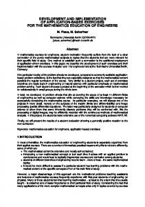
Fig 1.0 gives the overall system architecture of the Application Specific DVB RCS Hub. The HUB can be functionally divided into two segments the Forward Link Subsystem (FLSS) which generates all the data (traffic + signaling) to be up-linked to the satellite and the Return Link Subsystem (RLSS) which processes the data received from the Satellite Interactive Terminals. As per Fig 1.0 the HUB components are: PC based Forward Link Generator. Return Link Processor. Multi carrier Burst Mode Demodulator. DVB Modulator. GPS Integrated NTP Server. The Forward Link Generator is designed on a standard PC based system with LINUX O.S along with the Hub management software module. The Return Link Processing is carried on a separate PC on LINUX platform. The software receives data from Multi-Carrier Demodulator over LAN does IP decapsulation and sends Management & Control information to forward Link Generator PC over LAN. Commercially available Multichannel Multi-Frequency Burst mode demodulator proposed to be used, which can simultaneously demodulate four channels each from 64kbps to 2 Mbps. It receives the burst time plan from the HUB and distributes the IP over MPEG2 burst on LAN [7]. A commercially available DVB Modulator having ASI input [5] is used to modulate the data as per DVB-S standard. Commercially available GPS based Network Time Protocol Server is used to provide highly stable time and frequency source.
3.2 SCT/FCT/TCT/SPT Generator Generates the Superframe Composition Table, Frame Composition Table, Timeslot Composition Table and Satellite Position Table. These four tables combined gives the frequency plan of the return link to the terminal. The FCT , TCT , SPT are static tables and the contents generally don’t change. The SCT is a dynamic table and contains all information about a superframe like when the superfarme starts, how long it lasts and the sequence number of that superframe. It contains the superframe_start_time_base field which signifies the start of a superframe in terms of PCR ticks, duration field to specify the duration in terms of PCR ticks and superframe counter to signify the superframe number. The generator increments these value accordingly. Each new superframe is updated with the new value of PCR and count. This helps new terminals to know the current superframe going on and acquire the forward link.
3. Design of the Forward Link Generator The Forward link generator consists mainly of the following generators (i) NIT/PAT/PMT/PMT_RMT/RMT generator (ii) SCT/FCT/TCT/SPT generator (iii) Terminal Information Message generator (iv) Correction Message Table generator (v) Terminal Burst Time Plan generator (vi) Multicast Mapping Table generator (vii) Program Clock Reference generator The DVB-RCS service Information tables can be broadly divided into two categories static tables and dynamic
3.3 TIM Generator The TIM generator generates the Terminal Information Message Table. It can be an unicast TIM that is generated for a specific SITS or broadcast TIM that conveys such network conditions, which affect all terminals. The TIM contains the descriptors like logon_initialize_descriptors, ACQ assign descriptor, SYNC assign descriptor [1] needed to handle logon of terminals to the network and
2
inform specific information to SITs. The TIM generator is mainly used to handle logon of terminals to the network.
3.4 CMT Generator The CMT generator generates the Correction Message Table, which contains the timing, frequency and power corrections of all terminals in ACQ or SYNC phase. The CMT generator is needed during the coarse synchronization and fine synchronization and synchronization maintenance phase of the HUB Management.
(ii)
3.5 TBTP Generator
(iv)
(iii)
The TBTP generator generates the Terminal Burst Time Plan for all the terminals logged on to the network. The Hub for traffic assignment of terminals uses the generator, after it has passed the ACQ and SYNC phase.
4. IP Encapsulation and Multicasting The IP Encapsulation into DVB is done using the Multiprotocol Encapsulation as specified [8]. The software module for IP Encapsulation, which is an important function of the Forward Link Packet Generator, performs the following major functions (i) The software takes the multimedia streaming data through socket and packs the IP data into DSMCC Sections with the appropriate MAC address of the destination ROT/SIT. The IP Address to MAC translation is done using table lookup. (ii) The DSMCC sections can take a maximum of 4KB of IP data. So IP data with larger length have to be segmented by the software into multiple DSMCC Sections using the section number and last section number fields of DSMCC [1]. (iii) The software distributes DSMCC Sections containing IP Packets into 188 bytes MPEG2-TS packets which act as containers of the IP data. In case the length of the DSMCC Section does not match with the 184 bytes payload of MPEG2 TS the remaining space is stuffed with 0xFF.
3.6 MMT Generator The MMT generator generates the Multicast Map Table to signify the PIDs in which the multicast data is to be transmitted in the forward link.
3.7 PCR Generator The PCR generator generates the PCR packets as per the standard [1] on a separate PID. This PID is indicated to the network in the Program Map Table. The PCR is sent at a regular interval taking time from the system clock .The system clock is stabilized by installing a NTP Client in the Forward link Packet generator PC which takes NTP time from the GPS integrated NTP Server to synchronize its own system clock. This stabilized clock is used to generate the PCR
3.8 MPEG2 TS Generation The MPEG2 TS generator converts input data to MPEG2 transport stream. The generator takes as input IP Encapsulated data, DVB-RCS SI Tables and NCR and generates the TS for each stream and inputs it to the multiplexer which actually multiplex the TS and generates the MPEG2TS Mux data suitable to be up-linked to the satellite as per DVB-S standard. MPEG2-TS generator module perform: (i)
payload_unit start indicator field as 1 and the following TS packets will have this field as 0. Using these fields the receiver knows the start and end of fragmented TS data and does the reassembly. Handling the adaptation field control bit, which signifies whether the TS header is accompanied with the adaptation field. For IP encapsulated data and DVB-RCS table data this value is 01,if no adaptation field is used. If the input data is NCR data then this is 10. The 13 bit PID corresponding to that data has to be inserted. Continuity counter of 4 bits has to be incremented for each TS packet for all types of input.
The Forward Link Packet Generator supports Multicasting through the use of the Multicast Map Table (MMT) as defined by Sat Labs System Recommendations [9]. The MMT defines the PIDs associated with multicast IP addresses. It consists of sections called Multicast_to_PID_map, which are private sections as defined in MPEG-2 Systems standard.[9]
Handling the Payload_unit_start_indicator field in the TS Header. This 1 bit field controls the segmentation of the input data into multiple 188 bytes TS packet. The TS header, which contains the start of a new payload, will have the
5. Time and Frequency synchronization The overall synchronization of the network is based on satellite distributed NCR timestamps. This synchronization concept is based on program
3
thereby an instability of timing and frequency of the terminal.
synchronization methods originally used in MPEG2 through the use of the Program Clock Reference concept. The PCR basically represents the highly stable 27 MHz system clock at the HUB, which acts as the master clock for the network. PCR is 42 bit format where the first 33 bits represent a 33bit base counter driven at 90KHz thereby signifying a scaled down value of the network clock and the remaining 9 bits represent 9 bit modulo-300 extension counter. The terminals receive these PCR packets through the forward link and tries to generate an exact replica of the system clock using a PLL approach to remove low frequency jitter. The SIT uses a low crystal oscillator to generate 27MHz clock and compares its values with each received PCR packets thereby stabilizing the local clock. PLL is a feedback loop that uses an external signal (the incoming PCR packets in our case) to tune a local signal source (generated by the local Oscillator in our case) in order to generate a relatively more stable result signal (the receiver’s reconstructed local clock in our case) [21]. This stabilized clock at the terminal is used for two references. (i)
(ii)
5.1 PCR Re-stamping All data generated for the Forward link is subjected to buffering and a variable amount of time is taken in the generation of different SI tables and encapsulating the IP packets. So the PCR values generated will loose significance once it is buffered or gets generated with variable time. To keep the PCR jitter low the PCR generated values have to be re-stamped after the multiplexing phase and before outputting it to modulator. The Re-stamping software is implemented in a separate PC. The PC has a PCI based commercially available ASI card, which has input and output port. The card has the capability to simultaneously receive and transmit data. The main functionality of the software is to (i) Reads 188 byte from the ASI card and checks the PID of the TS. If the TS is not containing PCR or SCT the software writes the TS to the ASI card without any modification. (ii) If the PID is that of PCR the software modifies the PCR field with new values of the PCR counter. The Re-stamping software has a PCR counter running at 27 MHz, which is used for restamping. The value of this counter is divided by 300 to get the first 33 bits of PCR and the remainder forms the 9 bit extension of the 42 bit PCR. (iii) If the PID is that of SCT the software finds the sct_start_time_base and sets it to the current value of the PCR. The sct_start_time_base signifies the start of a superframe in terms of PCR count intervals. So if the PCR values are re-stamped the sct_start_time base also has to be updated to the new value.
Timing reference : The terminal uses the local clock for burst synchronization. The SCT,FCT,TCT,SPT combined tells the terminal about the overall return link configuration. From the TBTP and TIM the terminal gets the PCR count value in which it should transmit for its bursts like ACQ, SYNC and Traffic. It then uses its local clock to decide when to start transmission. An unstable local clock resulting from a jittered PCR will lead to burst synchronization error. Frequency reference: The SIT uses the PCR derived local clock as its frequency reference and needs a normalized carrier frequency accuracy better than 10-8. This lead to more stringent constraint on PCR accuracy and unlike timing accuracy, it cannot be solved by increasing the guard band of the burst [17].
6. HUB Management
The PCR packets may suffer from small variations called PCR jitter arising from buffering, truncation of PCR values and small processing variability. There can be an error introduced in the PCR during the time of generation in which case the PCR value itself is erroneous. It may also happen that the PCR is generated correctly but transmitted with variable delay so a correct PCR reaches the receiver at a wrong time. The DVB timing synchronization is based on the basic idea that there should be a constant time difference between the encoder and decoder side [18]. The fixed delay can be taken care of by sending the information in Optional PCR Insertion TS packets but the variable delay causes PCR jitter and
In order to be able to proceed with logon, the SIT should be in the Receive Synchronization State, which is reached after following the Initial synchronization procedure described in [1]. This means that for the SIT to logon to the network it should be able to acquire the forward link signaled by a state called “Forward Link Acquired” in the SIT GUI. The prime objective of HUB is to generate the forward link signaling so that after power on the SIT can acquire the forward link and be in a state from where it can logon to the network. Even if no terminal is logged on to the network the Hub should go on generating the signal needed for the initial synchronization procedure of the terminal.
4
(ix)
To enable the entry of an SIT into the system the HUB has to handle the signaling for the following phases. (i) Logon procedure (ii) Acquisition Coarse synchronization procedure (iii) Fine synchronization procedure (iv) Synchronization maintenance procedure (v) Terminal request handling procedure (vi) Traffic handling procedure (vii) Terminal Database handling (i)
(ii)
(iii)
(iv)
(viii)
Logon Procedure: Whenever a new terminal tries to logon in the network it uses the CSC Burst and sends its capability to the HUB. This burst contains the SIT MAC address and SIT capability, which the HUB should store for future requirement. After a CSC burst is received, the CSC processing module interacts with the Terminal Database Generator module to create an entry for that terminal. It also informs the TIM Generator to generate the unicast TIM Messages. Acquisition Coarse synchronization procedure: Whenever an ACQ burst is received, ACQ processing module informs the CMT Generator to handle the ACQ phase of that terminals by including the time, frequency and power corrections for that terminal in CMT Tables. The Hub uses group id and logon id assigned to the terminal during logon in the CMT table. Time, frequency and power deviations of the terminals are available from BMD output. Fine synchronization procedure: Whenever a SYNC burst is received, SYNC processing module informs CMT Generator to handle the SYNC phase of that terminals by including the time, frequency and power corrections for that terminal in CMT Tables using the group-id and logon-id assigned during logon.
(x)
Sync maintenance procedure: During the logon phase the SIT is instructed after how many superframes it should transmit the SYNC burst. In this case after every 32 superframes the SIT transmits a SYNC burst and the HUB maintains its synchronization generating the CMT using CMT generator. Terminal request handling procedure: This module processes the bandwidth request for a specific terminal and updates the bandwidth requirement entry for that terminal in the Terminal Database. Based on this the TBTP Generator decides if a new BTP has to be generated for the terminals in the network subject to bandwidth availability or continue with same BTP if constant rate assignment is used.
Traffic handling procedure: This module receives the data coming from terminal and puts it in the appropriate queue of data for that terminal. All terminals logged on to the network are associated with a traffic queue. The data has to be IP Decapsulated and depending on the destination IP, it will be sent to the IP Encapsulation Module through router for IP Encapsulation and put in the Forward Link. The IP encapsulation module will decide the DVB-MAC address to be used to reach the IP Address specified. Terminal Database handling procedure: The HUB maintains a database of all terminals, which are allowed to use the network. Before a terminal can use the network its MAC address has to be registered in the HUB. The HUB generates an entry of that terminal in the database where all relevant information for that terminal is kept. Whenever a terminal tries to logon to the network, the HUB checks its MAC address in the database to find out whether it is a registered user the HUB then looks at the availability of resources like availability of slots for that terminal wishing to login. The HUB uses an internal table, which stores the informations, like how many ACQ slots, SYNC slots and traffic slots are available and how much is free. For a terminal to be logged on to the network it has to maintain the synchronization procedure after a pre-negotiated interval of superframe. This poses an constraint on the number of terminals which can simultaneously remain logged into the network as the SYNC slots has to be reserved in advance for terminals logged in. Depending on the availability of the SYNC and ACQ slots the terminal is allowed to logon to the network. An unicast TIM is generated with the transmit_disable flag set to 0 in this case. The following parameters have to be stored in the database: Terminal MAC Address – The MAC address of the terminal allowed to use the network. Logon status : If logged in then 1 else 0. ACQ status : Either 0 signifying ACQ phase pending, 1 signify in ACQ phase and 2 signify ACQ phase over. SYNC status : Either 0 to signify SYNC pending, 1 if in SYNC and 2 is passed the SYNC phase Traffic status : Either 0 if waiting for traffic, 1 if in trafic and 2 if traffic is over
5
Traffic scheduling type: the type of scheduling used for the terminal like CRA or VBDC or RBDC.
Group_id : Group id of the terminal alocated after logon
The forward link generator modules use this database for generating unicast TIMs and CMTs for that terminal. The terminal database is presently implemented in RAM with some relevant information stored in file. Afterwards some standard database can be used when the number of terminals become more in the network.
Logon_id, : Login id of the terminal allocated after logon ACQ Superframe : The superframe counter in which to go for ACQ. ACQ slot : The slot number for ACQ
7. Implementation Approach
SYNC superframe: The superframe number in which to go for SYNC
Requested Data rate: Requested data rate available from the SAC field
The software is implemented in GNU C++ on LINUX Platform. The GUI of the software is developed using GTK on a Pentium IV PC. An Object Oriented Design approach is adopted in designing the software. All the Service Information tables, Descriptors, IP Encapsulated data and PCR are coded as separate objects, with associated routines of generating them as member functions. SI Table and IP Encapsulation objects inherit the general SI Headers objects and DSMCC Sections [1] objects. The Object Oriented programming concept of Abstraction, Multi-Level-Inheritance and Dynamic Polymorphism are extensively used in the software which gives the software its needed flexibility, reusability and ease in testing.
Allocated data rate : The present data rate allocated
8. Test and Experiments Conducted
Traffic Type : Either MPEG or ATM Log-on time : Time at which terminal logged on UTC time.
This section discusses the testing procedure and results. The system is tested at the baseband (IF) level as well in the Satellite link.
Logoff time : Time at which the treminal logged off
8.1 Offline Testing
SYNC slot : the slot in which to go for SYNC Traffic superframe : The superframe number in which to go for traffic Traffic slot : The slot number for traffic Number of traffic slot : total number of traffic slots
All the generated Forward Link Signaling data as well as IP Encapsulated data embedded in MPEG2-TS format is tested to be compliant to the standard using Verisat Forward Link Analyzer [16]. This is a commercially available standard DVB RCS protocol Analyzer and is proposed to be used for terminal and HUB compatibility test in SAT Labs [22].
Unicast IP traffic PID : The PID in which unicast IP will be sent to the terminal Management/Ctrl PID: The PID in which management and control information will be sent to the terminal
8.2 Satellite Link Testing
Time correction: the time correction value this value is obtained from return channel and used by the CMT generator for generating CMT.
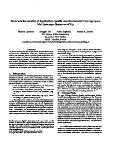
A third party audio/video streaming software is used for multicast streaming. The data generated through Forward link Packet Generator (Refer Fig 2.0) is transmitted to the DVB Modulator using DVB ASI interface, which in turn is up-linked to the Satellite in Ku Band. The streaming software is run at different data rates from 384Kbps to 1Mbps and the modulator was set at 1.844 Msps. INSAT 3A Ku Band transponder is used and the signals are
Frequency correction: the frequency correction value of the terminal Power correction: the power correction value of the terminal
6
Shukla and all staff members of Advanced Communication Technology Division for their advice and active technical support towards the realization of the work.
received through ROT. It de-capsulate the IP Packets and passes on to the destination PC where it is played using a third party Player.
8.3 L-Band Testing
References [1] ETSI EN 301 790: "Digital Video Broadcasting (DVB); Interaction channel for satellite distribution systems". [2] ETSI TR 101 202: "Digital Video Broadcasting (DVB); Implementation guidelines for Data Broadcasting". [3] Novra S75 –0100 Receiver Instructions in www.novra.com [4] Series 2000/3000 IDU User Manual from EMS Satellite Networks,Canada, www.ems.com [5] User Manual DM240 Digital Modulator from Radyne ComStream www.radyne.com [6]References of Tym Server 2000 from Symmetricom , www.symmetricom.com [7] Multi-Channel Multi-Frequency Burst Mode Demodulator Version 1.1 Specification. Doc:BMD-ABSP-SPE-0004 from Alcatel Bell Space N.V [8] Project Report on GSAT-3 (EDUSAT) Applications Programme Macch 2003 Space Applications Centre. [9] SatLabs System Recommendations January 2004 [10] ISO/IEC 13818-1 (1996): "Information technology Generic coding of moving pictures and associated audio information; Part 1: Systems". [11] ETSI EN 300 421: "Digital Video Broadcasting (DVB); Framing structure, channel coding andmodulation for 11/12 GHz satellite services". [12] ETSI ETS 300 802: "Digital Video Broadcasting (DVB); Network-independent protocols for DVB Interactive services". [13] ETSI EN 300 468: "Digital Video Broadcasting (DVB); Specification for Service Information (SI) in DVB systems". [14] ETSI EN 301 192: "Digital Video Broadcasting (DVB); DVB specification for data broadcasting". [15] A proposal On “Study, Simulation , & Proof Of Concept of DVB-RCS. [16] User Manuals on FRLA at www.verisat.no [17] Terminal timing synchronization in DVB-RCS systems using on-board NCR generation by Neale and Guy Begin Space Communications 17(2001) [18] Timing and synchronization using MPEG-2 Transport Stream by David K. Fibush SMPTE Journal July 1996 [19] Implementation of a New MPEG-2 Transport Stream Processor for Digital Television Broadcasting by Liang Longfei, Yu Songyu and Wang Xingdong, IEEE Transactions on broadcasting Vol 48 No 4 December 2002 [20]Implemetation of MPEG2 TS Remultiplexer and data transport unit for HDTV Satellite Broadcasting by Soo in Lee, Sung Bae Cho IEEE Trnsaction on Consumer electronics Vol 43 No 3 Augeust 1997 [21] A Realtime Software Solution for resynchronizing filtered MPEG2 Transport stream by Bin Yu, Klara Nahrstedt, University of Illinois [22] DVB-RCS Compliant Forward Link Packet Generator by Mohanchur Sarkar, N.G.Vasantha Kumar….,Dr.K.S.Dasgupta in National Conference On Communication NCC 2005. [23] www.fsmlabs.com Realtime Linux Pro
The Forward Link generator PC generates the Forward Link Signaling and passes it through a commercially available ASI card to the Re-stamping PC. The Re-stamp PC receives the data from the ASI card processes it and writes to the ASI card. The ASI card is connected with a DVB Modulator, which is then passed to a L-Band translator and given to the input of SIT. A BMD simulator is used in place to BMD, which simulates the return link parameters, as they would actually come from the Alcatel BMD on LAN. The Modulator and L-Band translator are feed with a GPS based 10 MHz clock.
8.4 Results The EMS SIT is accessible through a web based GUI. After getting the forward link data the SIT first locks to the PCR transmitted. Then it acquires the forward link signaled as “Forward link Acquired”. The SIT then logs on to the network using CSC burst and the HUB handles its logon and gives the slot, when it should go for ACQ and SYNC. The then passes through the ACQ and SYNC phase and ultimately comes to the ACTIVE state when it has got its TBTP and can transmit data as in Fig 3.0
9. Conclusion & Future Work The Application Specific DVB-RCS HUB will provide the necessary platform for IP Based e-Learning. The system can be used to unicast/multicast/broadcast live video/audio lecturers from HUB using Web camera with streaming software to be received by low cost ROT/SIT in remote places. This implementation is based on totally a softwarebased approach thereby reducing the cost of implementation. Presently the software works on a non real-time operating system. The software will be evaluated on a RTLinux Pro, which is realtime Linux Operating system, in the future [23]. The IP capturing will be done through RTL Net a real-time package for networking support. The PCR restamping software is also thought to be evaluated on a real time operating system.
Acknowledgement Authors are deeply indebted to Shri A.R. Dasgupta, former Deputy Director, SITAA for his encouragement and inspiration towards this work. We thank Mr. Vishal Agarwal, Mr. H.J. Kotecha, Mr. Y.R. Patel, Mr. B.P. Chaniara, Mr. J.K. Kharde, Mr. G.J. Doshi, Mr. A.P.
7
FLSS To Satellite
WWW
Ethernet (1)
Forward Link Generation PC
Internet Traffic
LINUX OS
Router
1. 2. 3. 4.
SI Table for MCD(Eth2)
LAN
ASI
PCR Restamp PC
DVB 3030 Modulator ASI BNC Output TS MUX
IP Encapsulation SI Table Generation PCR Generation MF-TDMA Scheduler
BNC Female GPS Based NTP Server BNC Female Multi carrier Demodulator
SMA Female Input L Band
From Satellite
RLSS
RLP PC receiving data from MCD + IP Decapsulation + sends M&C info to forward Link Generator PC
HUB CONFIGURATION USING SOFTWARE BASED TS GENERATOR Fig 1.0 INSAT 3A
APPLICATION SPECIFIC DVB RCS HUB
USER TERMINAL ( SIT/ROT )
LAN KU
LAN
ASI
DVB Modulator VIDEO STREAMING SERVER
FORWARD LINK GEN.
IDU
GPS NTP Server VIDEO CLINT
RLP
BMD
Fig. 2.0 Testing of Application Specific DVB-RCS HUB via Satellite INSAT 3A with user Terminal SIT/ROT
Fig 3.0 SIT Test Result 8