Briefly, 53.8 g of potassium cyanide dissolved in 50 ml water was added .... (HACH reagent) and 0.6 ml of 1 M ferric perchlorate were then added to give a brownish yellow ... 115, 13362â13407, doi:10.1021/acs.chemrev.5b00361 (2015).
www.nature.com/scientificreports
OPEN
Received: 4 October 2016 Accepted: 20 December 2016 Published: xx xx xxxx
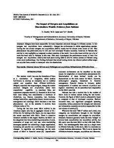
Implementation of concurrent electrolytic generation of two homogeneous mediators under widened potential conditions to facilitate removal of air-pollutants Muthuraman Govindan1, Alan M. Bond2 & Il-Shik Moon1 Electro-scrubbing is being developed as a futuristic technology for the removal of air-pollutants. To date, only one homogeneous mediator for the removal of air pollutants has been generated in each experiment using a divided electrolytic flow cell in an acidic medium. This paper reports the concurrent generation of two homogenous mediators, one at the anodic half-cell containing an acidic solution and the other at the cathodic half-cell containing a basic solution. The concept was inspired by the change in pH that occurs during water electrolysis in a divided cell. A 10 M KOH electrolyte medium assisted in the electrochemical generation of low valent 14% Co1+ ([CoI(CN)5]4−) mediator formed from reduction of [CoII(CN)5]3− which was accompanied by a change in the solution 'oxidation reduction potential' (ORP) of −1.05 V Simultaneously, 41% of Co3+ was generated from oxidation of CoIISO4 in the anodic halfcell. No change in the solution ORP was observed at the cathodic half-cell when both half-cells contain 5 M H2SO4, and Co3+ was formed in the anodic half-cell. An electro-scrubbing approach based on the above principles was developed and tested on gaseous-pollutants, CH3CHO and CCl4, by Co3+ and Co1+, respectively, with 90 and 96% removal achieved, respectively. The increasing concentration of atmospheric air-pollutants has prompted intensive research into the development of new environmentally friendly and affordable degradation methods. The generation of homogeneous mediators in aqueous media plays a key role in the mediated electrocatalytic oxidation (MEO) of air-pollutant degradation1, 2. Over the last decade, electrochemically oxidized metal ions, such as Ce4+, Ag2+ and Co3+, have been used as homogeneous mediators for pollutant degradation because of their very positive oxidation potentials, 1.4 V, 1.9 V and 1.8 V, respectively3–5, to generate what is considered as a futuristic technology by the United Nations Environmental Protection Agency (UN-EPA)6. In practice, these electrogenerated free metal ions, particularly Ag2+, are stable and soluble only under acid pH conditions (6 M) Co2+ becomes [CoII(OH)4]2− 23, which may be reduced electrochemically to low-valent [CoI(OH)4]3−. Figure 3B shows the electrolysis results when CoIISO4 and [CoII(CN)5]2− are present in the anodic and cathodic half cells containing 5 M H2SO4 and 10 M KOH as the electrolytes respectively. The initial shift in the ORP of the electrolyzed solution at each half-cell to 1.35 V and −1.05 V in 30 min highlights the formation of higher oxidation state Co3+ and lower oxidation state Co1+ in the relevant half-cells. This result confirms that the pH change and potential widening effect can allow the generation of two homogenous mediators concurrently using a single electrolytic cell. A [CoII(CN)5]3− to [CoI(CN)5]4− reduction process occurs under highly alkaline conditions at Hg electrode as shown in equations 7 and 8 with E0 = −1.2 V (SCE) applying to 4 M and higher KOH concentrations21, 24. A similar electrochemical reduction process is expected to occur at a Ag metal electrode with high KOH concentrations,
Scientific Reports | 7: 29 | DOI:10.1038/s41598-017-00058-2
3
www.nature.com/scientificreports/
Figure 3. Co3+ and Co1+ generation with acid and base in the half-cells on. ORP (■, □) and generation efficiency (○, ●) found in each half-cell during electrolysis with (A) 0.01 M CoIISO4 in both half-cells or (B) 0.01 M CoIISO4 in the anodic half-cell and 0.01 M [CoII(CN)5]3− in the cathodic half-cell. Conditions: Anolyte = 5 M H2SO4; Catholyte = 10 M KOH; Other experimental conditions are as in Fig. 1.
At the cathode: [CoII (CN)5 ]3 − + e− → [CoI (CN)5 H]3 − (inactive with [KOH] less than 4 M)
(7)
[Co1 +(CN)5 H]3 − + OH− → [Co1 +(CN)5 ]4 − + H2 O ( − 1.2V(SCE)with [KOH] greater than 4 M)
(8)
In additional experiments it was shown that with [Co (CN)5] in 5 M H2SO4, no change in the cathodic ORP occurred, as expected if no low-valent Co1+ formation had occurred (Fig. SI 1). This result confirms that high pH is essential in the cathodic half-cell in order to generate low-valent Co1+ mediators. To confirm that [CoII(CN)5]3− reduction can occur in the electrolysis conditions used above, experiments using cyclic voltammetry (CV) was undertaken in both acidic and basic media at a macrodisk Ag electrode (Fig. SI 2). The CV method showed that reduction of [CoII(CN)5]3− does occur (a reduction peak at −830 mV) in alkaline media (Fig. SI 2 curve b) whereas H2 evolution is favoured under acid conditions (Fig. SI 2 risinng part of curve a near 0 V) highlighting the need for a high pH in the cathodic half-cell in order to generate 2 mediators simultaneously. Oxidation of [CoII(CN)5]3− (not relevant to this paper) at about 0.65 V also is evident in curve b of Fig. SI 2. Importantly, the efficiency dependence on time (Fig. SI 3) data shows that when Co1+ and Co3+ are both generated simultaneously at the cathode and anode half cells, respectively, that the Co1+ yield increased when the current density increased from 20 to 30 mA cm−2 then decreased when a higher current density of 50 mA cm−2 was employed due to enhanced formation of inactive [Co(CN)5H]3− (eqn. 7) or further reduction to cobalt metal. In contrast, the Co3+ yield increased progressively with increasing current density as in our previous report25. The concentrations of Co1+ and Co3+ were 2.1 mM and 3.50 mM, respectively, after 6 h electrolysis at a current density of 50 mA cm−2. This shows that Co3+ and Co1+ formation competes effectively with gas evolution at both the anode and cathode during electrolysis. The efficiency of the generation of two mediators concurrently is an important practical consideration in an electrolytic cell. As shown in Fig. 3, the generation efficiency (current efficiency for the long term electrolysis (5 h) in dichloroethane is only 6%26) of Co3+ reached 41% at the anodic half-cell after 5 h operation. With the help of the cathodic half-cell operation, an additional 15% generation efficiency of Co1+ formation was achieved to give a total of 56%, with this new approach. II
Scientific Reports | 7: 29 | DOI:10.1038/s41598-017-00058-2
3−
4
www.nature.com/scientificreports/
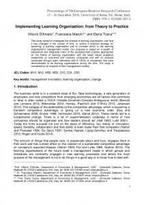
Figure 4. Cathodic half-cell application for CCl4 gas pollutant removal. Effect of electrogenerated Co3+ in the cathodic half-cell on removal of gaseous CCl4 as a function of electrolysis time with different electroscrubbing processes: (a) MER using [CoI(CN)5]4− in 10 M KOH; (b) DER using 10 M KOH. Electro-scrubbing conditions: Gas flow rate = 0.2 L min−1; Liquid low rate = 3 L min−1; Feed CCl4 = 8 ppm. Electrolysis conditions: Electrodes = Pt coated Ti (anode) and Ag (cathode) (50 cm2 area); Electrolyte volume = 500 ml (each side); solution flow rate = 2 L min−1; Current density = 30 mA cm−2.
Probing the membrane stability under highly acidic and basic conditions. Although Nafion 324 is used in the chloralkali process27, 28, the stability of the membrane was tested under the present harsh conditions. No prominent changes were observed in SEM images on either side of the membrane surface after electrolysis (Fig. SI 4) although evidence for the deposition of salts containing potassium, sulfur, aluminum, chlorine, and cobalt was obtained that in some cases might have come from impurities present in the supporting electrolyte. In further evaluation studies, four consecutive batch electrolysis runs were performed with Co3+ and Co1+ generation, to give the data provided in Fig. SI 5. The Co3+ and Co1+ concentrations observed remain constant within experimental error, which confirms the stability of the membrane under the harsh conditions employed. Application to air-pollutants. Using the simultaneous generation of the Co3+ and Co1+ homogeneous
mediators, two air-pollutants were removed by MEO and mediated electrocatalytic reduction (MER) using electro-scrubbing. Although the two mediators can be produced concurrently, quantitative assessment of air-pollutant removal by electro-scrubbing had to be undertaken by a stepwise approach due to practical limitations with the availability of only one online FTIR gas analyzer. The electrolytically-formed Co1+ in the cathodic compartment under the optimized current density was used to degrade CCl4 in a continuous process. Note that Chloro Volatile Organic Compunds (CVOCs) like CCl4 cannot be degraded at the anodic half-cell due to electrode fouling by polymerization29. When the concentration of Co1+ reached 14%, ≈8 ppm of CCl4 was injected at a gas flow rate of 0.2 L min−1 through the bottom of the scrubber at a liquid flow rate of 3 L min−1 with a closed loop catholyte circulation. As shown in Fig. 4 curve a, a rapid decrease in the outlet CCl4 to 0.3 ppm was observed and this trend was maintained for up to 1 h of operation, which is equal to 96% removal or 0.53 mg h−1 of CCl4 removed and 12.78 mg day−1 can be achieved if the same removal rate continues. In the absence of Co1+ in the electrolyte, the direct electrocatalytic reduction (DER) of CCl4 does not occur in the electrolyzed 10 M KOH solution. In this case (Fig. 4 curve b) an initial decrease is detected in the outlet followed by an increase with time, and ultimately returning to the level of the inlet (≈8 ppm), which equates to 0% removal. These data confirm that the CCl4 removal process follows an MER pathway, as shown in reaction 9. 4−
(with 10 M KOH)[CoI (CN)5 ]
3−
+ CCl4 → [CoII (CN)5 ]
+ product(s)
(9)
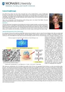
Additionally, the byproducts identified to accompany CCl4 removal by electro-scrubbing for I hour are chloride (Cl−) in solution and CO2 in the gas phase. In brief, the chloride concentration in the catholyte solution phase increases from about 1 to 1.66 g L−1 as shown in Fig. S 16. At the same time, the CO2 concentration in the gas phase increases to around the 30 to 40 ppm level and all CCl4 is removed as shown by increase in the gas phases FTIR CO2 stretching response in the 2289.9 to 2385.5 cm−1 range and a decrease in the CCl4 FTIR stretching response in the region 737.12–815.74 cm−1 (reference made to standard FTIR gas phase spectra available in the MIDAC library). In an anodic half-cell, electrolytically generated Co3+ was used to degrade CH3CHO through a continuous process. When the Co3+ concentration reached 41% by electrolytic generation, ≈30 ppm of CH3CHO was injected at a gas flow rate of 0.2 L min−1 through the bottom of the scrubber at a liquid flow rate of 3 L min−1 with closed loop circulation. As shown in Fig. 5 curve a, a rapid fall in the outlet CH3CHO to a concentration of 3 ppm (90% removal) occurs with this pattern continuing for up to 1 h of operation. The possibility of direct electrocatalytic oxidation (DEO) of CH3CHO (without presence of Co3+) was considered in an electrolyzed solution of Scientific Reports | 7: 29 | DOI:10.1038/s41598-017-00058-2
5
www.nature.com/scientificreports/
Figure 5. Anodic half-cell application for CH3CHO gas pollutant removal. Effect of electrogenerated Co3+ in the anodic half-cell on the removal of gaseous CH3CHO as a function of electrolysis time with different electro-scrubbing processes: (a) MEO using Co3+ in 5 M H2SO4; (b) DEO using 5 M H2SO4. Electro-scrubbing conditions: Gas flow rate = 0.2 L min−1; Liquid low rate = 3 L min−1; Feed CH3CHO = 30 ppm. Electrolysis conditions are the same as in Fig. 4.
5 M H2SO4 (Fig. 5 curve b). In this case, the initial decrease in the outlet concentration of CH3CHO ceased after 35 min, due to electrode fouling during DEO of CH3CHO25. In contrast, continuous removal of CH3CHO was achieved in the presence of electrogenerated Co3+ which confirms the removal process follows the MEO pathway without any additional reactions as shown in equation 10. Co3 + + CH3CHO → Co2 + + product(s)
(10)
Disscussion
In this investigation, widening of the potential range available by controlling the conditions used for water electrolysis has been utilised to generate two mediators simultaneously that facilitate effective air-pollutant removal, with one formed in each half cell. In a practical demonstration of the dual mediator generation approach, the degradation of one pollutant (CCl4) at the cathode and one (CH3CHO) at the anode was achieved simultaneously with efficiencies in both cases being greater than 90%.
Methods
Preparation of the cobalt cyanide complex. The cobalt cyanide complex ([CoII(CN)5]3−) was synthe-
sized according to a literature procedure30. Briefly, 53.8 g of potassium cyanide dissolved in 50 ml water was added to 60 ml of a cooled solution (4 °C) containing 40.0 g of CoII(NO3)2 under a nitrogen atmosphere (∼6.2 cyanide anions per cobalt), after which an equal volume of chilled alcohol was added. The resulting mixture was chilled slowly until thin violet platelets of the cobalt cyanide complex appeared. The solid was collected by rapid filtration, washed with cold alcohol, dried in a vacuum desiccator, and then stored in an air-tight brown bottle.
Electrolytic cell. The electrolytic flow cell used for the simultaneous generation of Co1+ at the cathode and
Co3+ at the anode was a plate-and-frame type, narrow gap, divided configuration4. The mesh type Pt-coated-Ti anode and a Pt/Ag, cathode were separated by a Nafion 324 membrane with the inter-electrode gap being maintained at 5 mm by two Viton rubber gaskets (2 mm thickness). The electrode assembly was clamped tightly with Ti end plates using a filter press technique. Separate channel paths were available in each compartment through which the anolyte and catholyte solutions could flow across their relevant electrodes. A 0.2 L solution of CoIISO4 (10 mM) in 5 M H2SO4 and 0.2 L of each of CoIISO4 in 5 M H2SO4, CoIISO4 in 10 NaOH, [CoII(CN)5]3− (10 mM) in 5 M H2SO4 or 10 M KOH were placed in separate anolyte and catholyte tanks, respectively. The anolyte and catholyte solutions were circulated continuously through the anode and cathode compartments of the electrochemical cell at a constant flow rate of 70 ml min−1 using peristaltic pumps (Masterflex - L/S, Model No. 7524-45, Cole Parmer Instrument Company, USA). The active Co1+ and Co3+ mediators were generated galvanostatically by applying constant current densities between 10 to 50 mA cm−2 using a DC power supply (Korea Switching Instruments). The effective surface area of each electrode exposed to the solution was 4 cm2. All measurements were carried out at 20 ± 2 °C. During gas-pollutant removal, a scrubber column (40 cm high and 5.5 cm (i.d.)) packed with 1 cm2 of Teflon tubes was attached to top of the anolyte and catholyte tanks respectively, which were already attached to the flow through electrolytic divided cell, as shown in Fig. SI 7. The cell had cathode and anode areas of 50 cm2 and an electrolyte volume of 500 ml. The scrubbing system consisted of an air supply system, a scrubbing solution ([CoII(CN)5]3−/[CoI(CN)5]4− in a KOH solution or Co2+/Co3+ in H2SO4 solution), a scrubbing reactor column, and an FTIR gas analyzer system (MIDAC Corporation, USA) equipped with a data logger. The anolyte and
®
Scientific Reports | 7: 29 | DOI:10.1038/s41598-017-00058-2
6
www.nature.com/scientificreports/ catholyte solutions were circulated continuously at a flow rate of 2 L min−1 using magnetic pumps (Pan World Co., Taiwan). For electro-scrubbing, the activated solutions were pumped separately into the scrubber column at a flow rate of 3 L min−1. CH3CHO and CCl4 gases (from RIGAS (1000 ppm), Korea) and air mixtures, which were obtained by the controlled mixing of air and CH3CHO or CCl4 gas using mass flow controllers (MFCs), were introduced to the relevant bottom of the scrubbers at a set gas flow rate. The CH3CHO or CCl4 gas to air ratios obtained using the MFCs were confirmed prior to undertaking the experiments. The scrubbing solution was re-circulated through the electrochemical cell to regenerate Co1+ or Co3+. Before starting the CH3CHO or CCl4 removal experiment, the electrochemical cell was operated until Co1+ or Co3+ conversions reached nearly a steady state, and the scrubbing solution was then pumped into the scrubber column. Cyclic voltammetry was carried out with a PARC VersaSTAT 3 instrument in a glass cell furnished with two compartments separated by a membrane. A platinum mesh and a dip type Ag/AgCl electrode were used as the counter and reference electrodes, respectively. Ag was used as working electrode, and were placed along with reference electrode in one of the cell compartments (acid or base as appropriate), while the counter electrode was placed in the other compartment.
Estimation of Co1+ and Co3+ concentrations. Aliquots (5 ml) of the catholyte containing Co1+ were
drawn periodically during the course of electrolysis experiments and the generated Co1+ concentration was calculated by titration against a standard [FeIII(CN)6]3− (1 mM) solution. The redox potential of the Co1+-containing solution was measured using an oxidation reduction potential (ORP) electrode (Model No. EMC 133, iSTEK, USA (6 mm Pt with Ag/AgCl reference electrode and gel electrolyte) with data obtained with a pH/ISE meter (iSTEK, pH-240L, USA) used to identify the end point during the titration. During each titration, [FeIII(CN)6]3− addition was stopped when the measured ORP value, which shifted to negative values with increasing Co1+ concentration, reverted to its initial value measured before electrolysis. The concentration of Co1+ was calculated from that of [FeIII(CN)6]3− consumed. In a similar manner, the Co3+ concentration from the anode compartment was obtained by titration with FeIISO4 (1 mM). Here, the initial ORP value of the Co3+-containing solution, which was approximately 600 mV, became increasingly positive with increasing Co3+ concentration. The concentration of Co3+ was calculated from that of the FeIISO4 titrant. The concentrations determined in this manner were reproducible to ±0.02 mM. Chloride ion analysis. The procedure used is based on that described in the user’s manual provided by HACH with their Model DR-2800 spectrophotomer. 5 ml of sample drawn from the electrolysis solution (catholyte) was neutralized with perchloric acid by titration and the resultant solution centrifuged to remove any precipitate present. If required, a final adjustment of the pH to 6–7 was made using 1 M NaOH. 0.8 ml of mercury thiocyanate (HACH reagent) and 0.6 ml of 1 M ferric perchlorate were then added to give a brownish yellow solution. The chloride content of this solution was then measured colorimetrically and the finally reported value determined after correction for dilution.
References
1. Martinez-Huitle, C. A., Rodrigo, M. A., Sires, I. & Scialdone, O. Single and Coupled Electrochemical Processes and Reactors for the Abatement of Organic Water Pollutants: A Critical Review. Chem. Rev. 115, 13362–13407, doi:10.1021/acs.chemrev.5b00361 (2015). (Washington, DC, U. S.). 2. Muthuraman, G. & Moon, I.-S. A review on an electrochemically assisted-scrubbing process for environmental harmful pollutant’s destruction. J. Ind. Eng. Chem. 18, 1540–1550 (2012). (Amsterdam, Neth.). 3. Muthuraman, G., Chung, S. J. & Moon, I. S. The combined removal of methyl mercaptan and hydrogen sulfide via an electro-reactor process using a low concentration of continuously regenerable Ag(II) active catalyst. Journal of Hazardous Materials 193, 257–263 (2011). 4. Govindan, M. & Moon, I.-S. A single catalyst of aqueous Co(III) for deodorization of mixture odor gases: A development and reaction pathway study at electro-scrubbing process. Journal of Hazardous Materials 260, 1064–1072 (2013). 5. Balaji, S., Chung, S. J., Thiruvenkatachari, R. & Moon, I. S. Mediated electrochemical oxidation process: Electro-oxidation of cerium(III) to cerium(IV) in nitric acid medium and a study on phenol degradation by cerium(IV) oxidant. Chem. Eng. J. 126, 51–57, doi:10.1016/j.cej.2006.05.021 (2007). (Amsterdam, Neth.). 6. Report of United Nations Environmental Programme on review of emerging innovative technologies for the destruction and decontamination of pops and the identification of promising technologies for use in developing countries. GEF, January 15, 2004. 7. Polczynski, P., Jurczakowski, R. & Grochala, W. Strong and Long-Lived Free-Radical Oxidizer Based on Silver(II). Mechanism of Ag(I) Electrooxidation in Concentrated H2SO4. J. Phys. Chem. C 117, 20689–20696, doi:10.1021/jp406442j (2013). 8. Pillai, K. C., Chung, S. J. & Moon, I.-S. Studies on electrochemical recovery of silver from simulated waste water from Ag(II)/Ag(I) based mediated electrochemical oxidation process. Chemosphere 73, 1505–1511, doi:10.1016/j.chemosphere.2008.07.047 (2008). 9. Bard, A. J., Parsons, R. & Jordan, J. Standard Potentials in Aqueous Solutions, (Marcel Dekker, New York, 1985). 10. Buriez, O., Nédélec, J.-Y. & Périchon, J. Stability and reactivity of electrogenerated cobalt(I) towards aryl halides in the presence of additives such as vinyl acetate or methyl vinyl ketone: Application to the electrosynthesis of arylzinc compounds. Journal of Electroanalytical Chemistry 506, 162–169, doi:10.1016/S0022-0728(01)00492-2 (2001). 11. Ulaganathan, M. et al. Recent Advancements in All-Vanadium Redox Flow Batteries. Advanced Materials Interfaces, n/a-n/a, 10.1002/admi.201500309 (2015). 12. Bard, A. J. & Faulkner, L. R. Electrochemical Methods: Fundamental and Applications, first ed., (John Wiley & Sons, New York, 1980). 13. Tsujiguchi, T., Iwakami, T. & Nakagawa, N. Effect of the Membrane Thickness on the Over-Potential Behavior of the Direct Formic Acid Fuel Cell. ECS Transactions 58, 1885–1891, doi:10.1149/05801.1885ecst (2013). 14. Habich, A. & Hausermann, H. R. Demonstration of the pH changes during the electrolysis of water. Journal of Chemical Education 64, 171, doi:10.1021/ed064p171.1 (1987). 15. Skripchenko, V. I., Zhitnyi, G. M. & Il’in, K. G. Electrolyte pH change during electrolysis of alkali metal and alkali earth metal chlorides of different concentrations. Tr. Novocherkassk. Politekh. Inst 197, 75–79 (1969). 16. Aoki, K. J., Li, C., Nishiumi, T. & Chen, J. Electrolysis of pure water in a thin layer cell. Journal of Electroanalytical Chemistry 695, 24–29, doi:10.1016/j.jelechem.2013.02.020 (2013).
Scientific Reports | 7: 29 | DOI:10.1038/s41598-017-00058-2
7
www.nature.com/scientificreports/ 17. Fabbri, E., Habereder, A., Waltar, K., Kotz, R. & Schmidt, T. J. Developments and perspectives of oxide-based catalysts for the oxygen evolution reaction. Catalysis Science & Technology 4, 3800–3821, doi:10.1039/C4CY00669K (2014). 18. Gong, M. et al. Nanoscale nickel oxide/nickel heterostructures for active hydrogen evolution electrocatalysis. Nat Commun 5, doi:10.1038/ncomms5695 (2014). 19. Yamaguchi, A. et al. Regulating proton-coupled electron transfer for efficient water splitting by manganese oxides at neutral pH. Nat Commun 5, doi:10.1038/ncomms5256 (2014). 20. Morales-Guio, C. G. et al. Photoelectrochemical Hydrogen Production in Alkaline Solutions Using Cu2O Coated with EarthAbundant Hydrogen Evolution Catalysts. Angewandte Chemie International Edition 54, 664–667, doi:10.1002/anie.201410569 (2015). 21. Hanzlik, J. & Vlcek, A. A. Formation of the pentacyanocobalt(I) ion in highly alkaline solutions. Journal of the Chemical Society D: Chemical Communications 47–48, doi:10.1039/C29690000047 (1969). 22. Minguzzi, A., Fan, F.-R. F., Vertova, A., Rondinini, S. & Bard, A. J. Dynamic potential-pH diagrams application to electrocatalysts for water oxidation. Chemical Science 3, 217–229, doi:10.1039/C1SC00516B (2012). 23. O’Donnell, T. A. In Comprehensive Inorganic Chemistry (ed J. C. Bailarh J. EmelÉUsronald Nyholma F. Trotman-Dickenson) 1009–1106 (Pergamon, 1973). 24. Lim, H. S. & Anson, F. C. Electrochemical behavior of pentacyanocobaltate(II) and substituted pentacyanocobaltate(III) complexes at mercury electrodes. Journal of Electroanalytical Chemistry and Interfacial Electrochemistry 31, 297–318, doi:10.1016/S00220728(71)80161-4 (1971). 25. Govindan, M., Chung, S.-J. & Moon, I.-S. Mineralization of Gaseous Acetaldehyde by Electrochemically Generated Co(III) in H2SO4 with Wet Scrubber Combinatorial System. ACS Combinatorial Science 14, 359–365, doi:10.1021/co300012a (2012). 26. Scialdone, O., Galia, A., Gurreri, L. & Randazzo, S. Electrochemical abatement of chloroethanes in water: Reduction, oxidation and combined processes. Electrochimica Acta 55, 701–708, doi:10.1016/j.electacta.2009.09.039 (2010). 27. Austin, J. H. Nafion Perfluorinated Membranes Operation in Chlor-Alkali Plants in Modern Chlor-Alkali Technology (ed. Wall, K.) 131–138 (Ellis Horwood, Chichester, 1986). 28. Grot, W. In Electrochemistry in Industry (eds Uziel Landau, Ernest Yeager & Diane Kortan) Ch. 8, 73–87 (Springer US, 1982). 29. Berríos, C., Arce, R., Rezende, M. C., Ureta-Zañartu, M. S. & Gutiérrez, C. Electrooxidation of chlorophenols at a glassy carbon electrode in a pH 11 buffer. Electrochimica Acta 53, 2768–2775, doi:10.1016/j.electacta.2007.10.053 (2008). 30. Adamson, A. W. Exchange Studies with Complex Ions. III. The Nature of the Complex Formed between Cobalt(II) and Potassium Cyanide, and its Exchange with Radiocyanide Ion in Aqueous Solution1. Journal of the American Chemical Society 73, 5710–5713, doi:10.1021/ja01156a063 (1951).
®
Acknowledgements
This study was supported by the National Research Foundation of Korea (NRF) funded by Ministry of Engineering Science and Technology (MEST) from the Korean government (Grant No. 2014R1A2A1A01001974).
Author Contributions
G.M. put forward the idea, performed the experiments and wrote the paper. A.M.B. and M.I.S. suggested additional work design, reviewed and edited the manuscript. All authors read and approved the final manuscript.
Additional Information
Supplementary information accompanies this paper at doi:10.1038/s41598-017-00058-2 Competing financial interests: The authors declare no competing financial interests. Publisher's note: Springer Nature remains neutral with regard to jurisdictional claims in published maps and institutional affiliations. This work is licensed under a Creative Commons Attribution 4.0 International License. The images or other third party material in this article are included in the article’s Creative Commons license, unless indicated otherwise in the credit line; if the material is not included under the Creative Commons license, users will need to obtain permission from the license holder to reproduce the material. To view a copy of this license, visit http://creativecommons.org/licenses/by/4.0/ © The Author(s) 2017
Scientific Reports | 7: 29 | DOI:10.1038/s41598-017-00058-2
8