The phase angle of the carrier ... the digitized carrier signal. .... [6] Gihad Elamary, Graneme Chester, Jeffery Neasham, A simple Digtal VHDL QPSK Modulator ...
Available online at www.sciencedirect.com
ScienceDirect Procedia Technology 25 (2016) 435 – 442
Global Colloquium in Recent Advancement and Effectual Researches in Engineering, Science and Technology (RAEREST 2016)
Implementation of Digital Modulator Using Digital Multiplier for Wireless Applications in Verilog and Cadence *Usha S.Ma, Dr. K.R. Natarajb *a
Department of Electronics and Communication Engineering, JSS Academy of Technical Education, Bangaluru-560 060, Research scholar - VTU Belgaum, India. bDepartment of Electronics and Communication Engineering, SJB Institute of Technology, Bangaluru-560 060, India.
Abstract The digital communication is more advantageous than analog communication. Digital components and subsystems are easy to build than analog components. As the implementation in VLSI technology progressed, the cost of the integrated circuits is gradually reduced. The components used in digital communication systems are robust and insensitive to atmospheric conditions and ensures good protection against noise and interference.The digital design offers more flexibility than analog design. The proposed digital Quadrature Phase Shift Keying(QPSK)modulator is based on digital multiplier called booth multiplier. This work is simulatedin Integrated Simulated Environment (ISE), Incisive simulators of Xilinx9.1i and Cadence tool respectively. The code is synthesized using Cadence RTL compiler and implemented on Field Programmable Gate Array (FPGA) spatan3 kit.The performance parameters such as power, area, and timing are analyzed and compared. This proposal gives better results than the conventional method of using analog multiplier for QPSK system. © 2016 2015The TheAuthors. Authors.Published Published Elsevier © byby Elsevier Ltd.Ltd. This is an open access article under the CC BY-NC-ND license (http://creativecommons.org/licenses/by-nc-nd/4.0/). Peer-review under responsibility of the organizing committee of RAEREST 2016. Peer-review under responsibility of the organizing committee of RAEREST 2016 Keywords:QPSK; FPGA; Cadence; Verilog; Booth Multiplier;WIMAX; FDMA; TDMA; CDMA;
1. Introduction One of the basic problems of communication engineering is the design and analysis of systems.This allows many individual messages to be transmitted simultaneously over a single communication channel.The technique used for multiple transmissions is called multiplexing. The multiple access techniques are Frequency Division Multiple Access (FDMA), Time Division Multiple Access (TDMA) and Code Division Multiple Access (CDMA).The advanced modulation techniques are used with multiple access technology to increase the data rate of a communication system,on the same available spectrum [1]. The higher order modulation techniques are more bandwidth efficient than
2212-0173 © 2016 The Authors. Published by Elsevier Ltd. This is an open access article under the CC BY-NC-ND license (http://creativecommons.org/licenses/by-nc-nd/4.0/). Peer-review under responsibility of the organizing committee of RAEREST 2016 doi:10.1016/j.protcy.2016.08.129
436
S.M. Usha and K.R. Nataraj / Procedia Technology 25 (2016) 435 – 442
lower order modulation techniques. Comparing QPSK (Quadrature Phase Shift Keying) modulation system with the BPSK (Binary Phase Shift Keying), QPSK is more bandwidth efficient than the BPSK. In this paper, QPSK modulation system implementation is shown using 8-bit Booth Multiplier. Since the parameters of the analog multiplier, various with the changes in the atmospheric conditions. The analog multiplier is replaced by digital multiplier. The first part of the paper explains about the basic digital communication block diagram and description [2, 3]. The second part of this paper describes the conventional method of QPSK system. The third part discriminate the Booth Multiplier for QPSK system. The fourthpart distinguishes and trace out the results, analysis and comparison. 1.1. Introduction to Digital Communication System The communication can be analog or digital. It may be wire-line or wireless.The telephone, television, radio, FAX and e-mail are the various forms of communication.These are all become an integral part of our daily lives. Life cannot be imagined without them. The basic digital communication block diagram is shown in Fig1. It consists of the source, the source encoder, channel encoder and digital modulator at the transmitter side. The digital demodulator, the channel decoder and source decoder at the receiver side. The physical channel connects the transmitter and the receiver.
Fig. 1. Basic digital communication block diagram.
x The original information signal is converted in to digital format by using analog to digital converter. x Source encoder does the data compression by avoiding redundancy in the incoming bit stream. x Channel encoder introduces redundancy into the bit stream at its input in order to provide some amount of errorcorrection capability to the data being transmitted. x Digital modulator and demodulator are used for mapping and de-mapping the data respectively. x Finally channel and source decoders reproduces the data. 1.2. Conventional Quadrature Phase Shift Keying (QPSK) System The Quadrature Phase Shift Keying (QPSK) is one type phase of modulation system. The phase angle of the carrier signal is varied according to the message signal. The conventional QPSK system consists of analog multiplier is shown below in Fig. 2.The QPSK signal is represented as shown in the equation (1). The four possible phase signals of QPSK are Π/4, 3Π/4, 5Π/4 and 7Π/4. In equation (1) the E is the signal energy and τ is the symbol duration. The four phases can be represented in gray encoded dibits as 11, 01, 00 and 10 respectively. The QPSK gives the same bit error rate as that of the BPSK, but requires only half the bandwidth required for BPSK. Since the symbol duration for QPSK is
437
S.M. Usha and K.R. Nataraj / Procedia Technology 25 (2016) 435 – 442
twice the bit duration of BPSK. Thus QPSK is more Bandwidth and power efficient than BPSK. Si(t) = ξሺʹܧȀ߬ሻ
ቂʹߎ݂ܿ ݐ Si(t) = 0 ; otherwise
ሺଶିଵሻࢰ
ቃ; Ͳ ݐ ߬
(1)
Fig. 2. The conventional QPSK modulator.
2. Proposed Quadrature Phase Shift Keying (QPSK) System The various types of digital multipliers are available namely, booth multipliers, combinational multiplier, wallace tree multiplier, array multiplier, and sequential multipliers.The proposed QPSK modulator with digital multiplier is shown in Fig. 3. In this diagram the multiplication is performed by booth multiplier.
Fig. 3.The proposed QPSK modulator with digital multiplier.
438
S.M. Usha and K.R. Nataraj / Procedia Technology 25 (2016) 435 – 442
The booth algorithm is used to multiply two signed numbers. The signed numbers are in two’s complement format. The binary message stream is converted in to parallel bits of data. This data is the multiplicand and the multiplier is the digitized carrier signal. The multiplication is performed by using booth multiplier. This multiplier is advantageous in terms of speed. The Fig. 4. Shows the booth multiplier symbol. The multiplier is the 8-bit data source is stored in register (A) and the multiplicand is the carrier in-phase and quadrature data are stored in other register (B). The multiplier result is loaded in register C (16-bit).
Fig. 4.The Booth multiplier symbol.
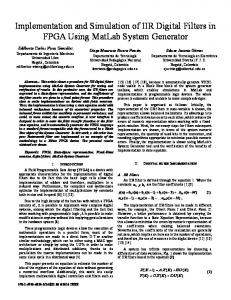
The booth algorithm is shown in Fig. 5. The function of the algorithm is to determine the beginning and end of a string of 1’s in the multiplier.
Fig. 5. The flow chart of Booth multiplication algorithm.
439
S.M. Usha and K.R. Nataraj / Procedia Technology 25 (2016) 435 – 442
A string consists of one or more consecutive 1’s and performs multiplicand addition and accumulation at the beginning of the string. For multiplication C= multiplier (A) * multiplicand (B). It can also be written as A= {(2 end1+1 – 2 begin1) + (2end2+1 – 2begin2) +--} C= {(2
end1+1
B -2
begin1
)
B + (2
end2+1
B– 2
begin2
(2)
B)+---}
The steps and explanation for the algorithm is given below. x Read input 8 bit data (multiplier A (n)) and carrier data ( multiplicand B (n)) x Initialize 1 bit transition detector register E=0, and index bit I = 0 x Concatenate E and A (i) x If {A [i], E} is 10 subtract B from the output C x If {A [i], E} is 10 add B to the output C x Else If {A [i], E} is 00 or 11, perform arithmetic right shift on C and copy the value of A [i] to E x Increment the index register I x If the operation is over, the final product will be stored in the register C 3. Results, Analysis and Comparison In this section, theresults are analyzed and compared with the existing conventional method. The design is simulated and implemented on Xilinx 9.1i, Spartan3 FPGA kit and synthesized using Cadence RTL compiler.The power, area, and speed parameters are analyzed and compared. The simulated results are shown in the Fig. 6 and 7 for various input values. The Table 1 shows the results of 8bit multipliers. The inputs A and B are the multiplier and multiplicand respectively. The result is stored in the output destination register C. The different values are forced for the inputs A and B. the output register value C is verified accordingly. For Example if the values of input A and input B 37 and 31 respectively, then the value stored at the output register C is 1147 in decimal signed. Similarly for other different values the results are verified and represented in Table1. Table 2 shows the output for different input values in hexadecimal. If the value of the input A in hexadecimal 8’h02 and input B is 8.h0D, then the result obtained is 16’h001A. Table 1. Output of multiplier for different values of inputs in Xilinx ISE simulator Time
200ns
400ns
600ns
800ns
1000ns
1200ns
1400ns
1600ns
Input [A]
5
5
37
45
45
37
39
39
Input [B]
0
27
11
Output [C]
0
1053
429
5 5 13 15 31 Fig. 6. shows simulated results for 8bit inputs in booth multiplier example1. 25 185 585 675 1147
440
S.M. Usha and K.R. Nataraj / Procedia Technology 25 (2016) 435 – 442
Table 2. Output of multiplier for different values of inputs in Xilinx ISE simulator Time
200ns
400ns
600ns
800ns
1000ns
Input [A]
8’h02
8’h02
8’h0A
8’h0A
8’h02
8’h22
Input [B]
8’h0D
8’h18
8’h18
8’h1A
8’h12
8’h1A
16’h001A
16’h0030
16’h00F0
16’h0104
16’h0024
16’h0374
Output [C]
1200ns
3.1. Xilinx (XST) synthesis Report Device utilization summary is represented in Table 3 and Table 4. The device utilization in conventional and proposed method isrepresented. As mentioned in Table3, in conventional method, the number of slices used is 80 out of 3584. The number of 4 input LUTs used is 174 out of 7168, number of bonded IOBs used are 30 out of 97, percentage slice utilization is 1%, LUT’s utilization is 1% and bonded IOBs 30%.
Table 3. Device utilization summary of conventional method Logic utilization
Used
Available
Utilization
No of slices
80
3584
No of 4 input LUTs
174
7168
1%
1%
No of bonded IOBS
30
97
30%
In percentage slice utilization is 1%, LUT’s utilization is 1% and bonded IOBs 28%.
As mentioned in Table 4, in proposed method for 8-bit, the number of slices used is 62 out of 3584. The number of 4 input LUTs used is 114 out of 7168 and number of bonded IOBs used are 28 out of 97.
Table 4. Device utilization summary of proposed 8-bit booth multiplier method Logic utilization
Used
No of slices
62
Available 3584
1%
Utilization
No of 4 input LUTs
114
7168
1%
No of bonded IOBS
28
97
28%
Comparing Table 3 with the Table 4, the number of slices, LUT’s and bonded IOBs used in proposed work is less compared to the earlier work. 3.2. Cadence synthesis Report The synthesis is done by using Cadence RTL synthesis tool. The synthesized output is shown in the below Tables. The Tables 5 and 6 represents the power report of conventional and proposed method respectively.In Table 5, the total power consumption of present system is representedas 91674.03nw. Table5. the power report of conventional method Instance
cells
booth8
650
Leakage power (nw) 7682.53
Dynamic power (nw) 83991.52
Total area (nw) 91674.03
S.M. Usha and K.R. Nataraj / Procedia Technology 25 (2016) 435 – 442
In Table 6, the total power consumption of booth multiplier method is 76442.156nw. By comparing Table 5 and 6, it can be concluded that power consumption in proposed booth multiplier method is less compared to the convention QPSK method.
Table6. the power report of proposed method Instance
cells
booth8
542
Leakage power (nw)
Dynamic power (nw)
6406.050
70036.106
Total power (nw) 76442.156
Tables 7 and 8, represents the area report of conventional method.In Table 7, the total areaused for present system is 2790 and proposed system is 2327 as shown in Table 8. Table 7. Area report of conventional QPSK method Instance
cells
Cell Area
booth8
650
2790
Net Area 0
Total area 2790
Table 8. Area report of proposed QPSK method Instance
cells
Cell Area
booth8
542
2327
Net Area
Total area
0
2327
By comparing Table 7 and 8, it can be concluded that area utilization in proposed booth multiplier method is less compared to the convention QPSK method. Tables 9 and 10 represents the gate delay report of conventional method and proposed method respectively. The delay in proposed booth multiplier method is minimized compared to the convention QPSK method.
Table9 Timing Constraints: gate delay of conventional method Logic
Route
Total
14.983ns
11.839ns
26.822ns
Table10. Timing Constraints: gate delay of proposed method Logic 11.622ns
Route
Total
9.91ns
21.532ns
Table 11and 12 shows the gata utilization reports of conventional and proposed techniques. Gate utilization is less in proposed technique compared to the conventional method. Table 11. Gate utilization report of conventional QPSK method Type
Instances
Area
Area%
Inverter Logic Logic
49 601 650
101.73 2688.27 2790
3.5 96.5 100.0
441
442
S.M. Usha and K.R. Nataraj / Procedia Technology 25 (2016) 435 – 442
Table12. Gate utilization report of proposed method Type
Instances
Area
Area%
Inverter Logic Logic
38 504 542
80.438 2246.630 2327.069
3.5 96.5 100.0
4. Conclusion Wireless communication has become the part and parcel of our daily life. The electronics components and subsystems needed in our daily life should consume less power, area and should be faster.The proposed technique using booth multiplier for QPSK systems, achieves good performance in terms of area, speed and power compared to conventional way of designing QPSK system.The work is synthesized using Cadence RTL compiler and implemented on FPGA Spartan 3 kit. The parameters are analysed, compared and concluded that proposed method imparts a better results than the conventional method. Acknowledgements I sincerely thank our research guide Dr. K. R. Nataraj for his consistent support. I would like to express my gratitude to my working organization JSS ATE and the Research Centre SJBIT for proving the lab facility to complete this work. Sincerely I thank to the University VTU Belgaum for proving the opportunity for registration.
References [1] Tarik Kazaz, Mrima Kullin, Mesud Hadzialic. Design and Implementation of SDR Based QPSK Modulator on FPGA. Sarajevo, Bosnia and Herzegovina: 2013; 613-618, MIPRO 2013/CTI. [2] Sarita singh, Sachin Mittal. VHDL Design and Implementation for optimum delay and area for Multiplier and Accumulator unit by 32 bit requntial multiplier. International Journal of engineering Trends and Technology: Vol3 issue 5-2012. [3] S.O. Popescu, A.S. Gontean and D. Ianchis. Implementation of a QPSK system on FPGA, IEEE 9thInternational Symposium on intelligent Systems and Informatics: September 8-10, 2011, Subotica, Serbia. [4] Wenmiao Song, Qiongqiong Yao, Design and Implement of QPSK Modem Based on FPGA. Baoding, Chna; 2010; 599-061; Volume 9; 2010 IEEE. [5] W.Song, Q. Yao, Design and implementation of QPSK Modem Based on FPGA.2010. [6] Gihad Elamary, Graneme Chester, Jeffery Neasham, A simple Digtal VHDL QPSK Modulator Designed Using CPLD/FPGAs for Biomedical Devices Applications. WCE 2009, July 1-3, 2009, London, and U.K: ISBN: 978-988-17012-5-1. [7] M. Speth, S.A. Fechtel, G. Fock, and H. Meyr.Optimum Receiver Design for Wireless Broad-Band Systems Using OFDM-PartI.IEEE Trans. Commum., vol. 47, no 11, Nov. 1999. [8] M. Speth, S.A. Fechtel, G. Fock, and H. Meyr.Optimum Receiver Design for Wireless Broad-Band Systems Using OFDM-Part II. IEEE Trans. Commum., vol. 47, no 11, Nov. 2001.