Digital Up-Converter (DUC) using a Xilinx Virtex6 FPGA. All the steps ..... Power spectral density (PSD) for the input signal is showed in Figure 8. Fig. 8. PSD of ...
FPGA Design and Implementation of Digital UpConverter using Quadrature Oscillator Felipe Augusto P. de Figueiredo, Fabbryccio A. C. M. Cardoso, José Arnaldo B. Filho, Karlo G. Lenzi and Fabrício L. Figueiredo DRC – Convergent Networks Department CPqD – Research and Development Center on Telecommunications Campinas, SP - Brazil {felipep, fcardoso, jbianco, klenzi, fabricio}@cpqd.com.br Abstract—In this paper we design and implement a complex Digital Up-Converter (DUC) using a Xilinx Virtex6 FPGA. All the steps necessary to build such circuits are thoroughly described and some valuable hints on how to overcome problems during the design time are presented. We introduce a new approach for oscillator circuits, which are an important part of any DUC design. Such oscillator approach is stable, clean, accurate and easily tunable. It is also RAM memory efficient, consuming no block RAM and a small amount of logic. Keywords—Digital Up Converter (DUC); Field-Programmable Gate Array (FPGA); Polyphase filter; Complex Multiplier, Quadarture Oscillator; Virtex6.
I.
INTRODUCTION
As one of the main digital signal processing tasks present in almost every digital transmitter, Digital Up-Converter (DUC) plays a crucial role in the realization of communication systems. It performs two fundamental functions including frequency channel switching and up-sampling conversion, which are usually employed in transmitters to filter, up-sample and modulate signals from baseband to the desired carrier frequency. DUCs are digital circuits, which convert a digital baseband signal into a pass-band signal. The input baseband signal is sampled at a relatively low sampling rate then the baseband signal is filtered and converted to a higher sampling rate before modulating a direct digitally synthesized carrier frequency. For instance, in digital transmission, baseband signals are up-converted to IF frequency, then modulated by IF sinusoidal carriers. The digital IF carriers and information signals are converted to analog signals by a high-speed, digital-to-analog converter (DAC), and finally modulated onto carrier signals by an analog voltage-controlled oscillator [2].
II.
FUNCTIONAL DESCRIPTION
Digital up-converters translate base band signals to higher frequency bands. This is done by first up-sampling the base band signal to the required sampling frequency and then mixing it with a high-frequency carrier. It achieves this by performing: interpolation to increase the sample rate, filtering to provide spectral shaping and rejection of interpolation images, and mixing to shift the signal spectrum to the desired carrier frequencies. The sample rate at the input to the DUC is relatively low; for example, the symbol rate of a digital communications system, while the output is a much higher rate, generally the input sample rate to a Digital-to-Analog Converter (DAC), which converts the digital samples to an analog waveform for further analog processing and frequency conversion [4]. A generic architecture for a DUC is shown in Figure 1. Digital Signal Source
L
LPF
X
DAC
~
DUC
Fig. 1. Generic DUC Architecture.
III.
PROPOSED DUC ARCHITECTURE
Table I lists the requirements for the implementation of DUC architecture proposed here. TABLE I.
DUC REQUIREMENTS
Parameter
It is widely accepted that FPGAs are a good choice for implementation of DUCs [1]. However, implementing DUC in FPGA is not an easy task, as many system design factors such as algorithm, HDL coding and cost need to be considered [3].
Input Bandwidth (BW)
This paper presents the case study and results of the implementation of a DUC circuit.
Value
307200 Hz
Input Sample Frequency (Fsin)
10.240 MHz
Output Sample Frequency (Fsout)
30.720 MHz
Quadrature Oscillator Frequency (fo)
3.072 MHz
Up-sampling Factor (L)
3
Input Signal Width
16 bits (Q15)
Ouput Signal Width
Full Precision
Figure 2 depicts the architecture proposed for the DUC implemented for this paper. As can be seen, the DUC has two identical paths, one for the I-input and the other for the Qinput. For this reason, it is also referred to as a complex DUC [5]. The input signal is first up-sampled to the required output sampling frequency of 30.720 Msps before mixing with the output of a Quadrature Oscillator to then produce the spectrum centered on the desired modulation frequency.
window, which has an independent control over the parameter α.
Fig. 3. Architecture of the polyphase filter.
The frequency and phase responses of this single rate filter are shown in Figures 3 and 4 respectively. The filter was designed by using the MATLAB Filter Design and Analysis Tool (FDATool). Fig. 2. Proposed DUC Architecture. Filter Response
A. Polyphase Filter Sampling-rate converters have a considerable amount of built in redundancy in terms of the required computational effort. In the case of a interpolator with L >> 1, all of the input samples are processed by the low-pass filter, but only every Lth sample of the filter output is used. Here most of the samples that are being processed by the low-pass filter are zero samples inserted between the original samples. Consequently, many of the operations are multiplications by zero. Polyphase filters are a smart way of doing sampling-rate conversion once they take into account that most of the samples being processed are zero, which leads to very efficient implementations. The architecture of the polyphase filter used in this paper is showed in Figure 3. The filters making up the polyphase filter are implemented in fixed-point mode. The input/output word length and fraction length are showed in Figure 3. The low-pass filter employed in the polyphase filter is a 33-tap symmetrical linear phase FIR filter with Kaiser windowing. This is a parametric kind of
20
0
Magnitude (dB)
ï20
ï40
ï60
ï80
ï100
ï120
0
2
4
6
8 10 Frequency (Hz)
12
14
16 6
x 10
Fig. 4. Magnitude response of the FIR Filter. Phase Response 0 ï2 ï4 ï6 Phase (in radians)
The sampling rate of the input signal is assumed to be 10.240 Msps. This signal has to be up-sampled by a factor L of 3 to achieve a sampling rate of 30.720 Msps. The up-sampling procedure can be performed by two different circuits namely, Cascaded Integrator-Comb (CIC) or Polyphase filters. Here we have decided to use the latter option once CIC filters are used when the up-sampling factor is greater than 10 and they present a sinc-like frequency response. The highly symmetric structure of a CIC filter allows efficient implementation in hardware. However, the disadvantage of a CIC filter is that its pass band is not flat, which is undesirable in many applications [6]. Therefore the input signal passes through the polyphase filtering stage, which filters the signal with a low-pass interpolating filter and performs a sampling rate change.
ï8 ï10 ï12 ï14 ï16 ï18 ï20
0
0.2
0.4 0.6 0.8 Normalized Frequency (x pi rad/sample)
Fig. 5. Phase response of the FIR Filter.
1
The filter specifications are summarized in Table II. TABLE II. Parameter
FILTER SPECIFICATION Value
Symmetrical Low-pass Linear Phase FIR
Filter type Order
32
Normalized Cut-off frequency
1/L
Stop-band Attenuation (dB)
40
Peak-to-peak ripple (dB)
0.004
Coefficient quantization
16 bits (Q15)
Output sample rate (Msps)
30.720
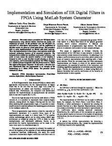
B. Quadrature Oscillator The up-sampled signal out of the Polyphase FIR filter is then mixed with complex exponential with frequency equal to the shift we ant to apply to the input signal. The sine and cosine output components of the complex exponential are multiplied with Polyphase filters I and Q channels respectively. The input signal spectrum is shifted from centered at 0 Hz to an intermediate frequency in the range of [-Fsout/2, Fsout/2], where Fsout = 30.720 MHz. The frequency translation process would normally require a Direct Digital Synthesizer (DDS) and a mixer. However, for the DUC proposed here we have adopted a different approach to generate the complex exponential signal used to translate the input signal. This approach is known as Quadrature Oscillator and its architecture is presented in Figure 6.
The computations done for each of the outputs is given by equations (1) and (2): !! ! = !! ! − 1 cos(!) − !! ! − 1 sin(θ)
(1)
!! ! = !! ! − 1 sin(!) − !! ! − 1 cos(θ)
(2)
The theory of operation of the quadrature oscillator proposed here is very simple [7]. Each new complex output sample is the previous output sample rotated by q radians, where q is 2πfo/fs with fo and fs being the oscillator tuning frequency and the sample rate, respectively, in Hz. To start the oscillator, we set the initial conditions of yi(n– 1) = 1 and yq(n–1) = 0 and repeatedly compute new outputs, as time index n advances, using Equations (1) and (2). This oscillator is called a coupled quadrature oscillator because both of its previous outputs are used to compute each new in-phase and each new quadrature output. It's a useful oscillator because the full range of tuning frequencies is available (from nearly zero Hz up to roughly fs/2), and its outputs are equal in amplitude unlike some other quadrature oscillator structures [7]. The tough part, however, is making this oscillator stable in fixed-point arithmetic implementations [8]. Depending on the binary word widths, and the value q, the output amplitudes can either grow or decay as time increases because it's not possible to represent ejq having a magnitude of exactly one, over the full range of q, using fixed-point number formats. The solution to amplitude variations is to compute y’i(n-1) and y’q(n-1) and multiply those samples by an instantaneous gain factor G(n) as shown in Figure 6. The trick here is how to compute the gain samples G(n) [9]. In this work we employ a linear automatic gain control (AGC) method as described in [9]. The circuit for the AGC is depicted within the dashed square in Figure 6. The AGC method greatly enhances the stability of the quadrature oscillator. Because this oscillator is guaranteed stable, and can be dynamically tuned, it's definitely worth considering for realvalued as well as quadrature oscillator applications [7]. C. Complex Multiplier The mixer is basically a complex multiplier which multiplies the up-sampled input signal (interpolation filter output) with the complex exponential generated from the quadrature oscillator. The multiplication of two complex numbers, a + jb and c + jd, results in the complex product: ! + !" = ! + !" ! + !" = !" − !" + !(!" + !")
(3)
The architecture of the complex multiplier being used in this case study is showed in Figure 7 and follows the operations presented in Equation (3). It requires 4 multiplications and 2 additions as we consider a subtraction as being an addition in 2’s complement.
Fig. 6. Quadrature Oscillator Architecture.
It is a well-behaved digital quadrature oscillator, whose output is yi(n) + jyq(n).
Input signal 5 0
X: 3.075e+005 Y: 1.218
ï5
Watts/Hz (dB)
ï10 ï15 ï20 ï25 ï30
Fig. 7. Complex Multiplier Architecture.
ï35
IV.
ï40
RESULTS AND DISCUSSIONS
Number of Slice Registers Number of Slice LUTs Number of occupied Slices Number of bonded IOBs Number of RAMB36E1/FIFO36E1s Number of BUFG/BUFGCTRLs Number of DSP48E1s Fmax (MHz)
RESOURCE UTILIZATION OF THE DUC. Used Resources
Available Resources
Utilization (%)
1,290
301,440
1%
26,135
150,720
17%
6,876
37,680
18%
157
600
26%
0
416
0%
2
32
6%
0 11.402 MHz
768
0%
A system clock frequency of 11.402 MHz is achieved for the DUC design in the XC6VLX240T device. We have designed all blocks present in this DUC implementation including multipliers, adders and MACs, which are the building blocks for the DUC implementation. This is the reason why there is no inferred DSP48 block in this circuit implementation. One of the possible reasons for the low operating frequency of the circuit is the use of combinational logic for the implementation of the multiplier and adder circuits. The other reason is that no pipeline has been taken into account, which hugely decreases the operating frequency. The input signal to the DUC was generated from a complex exponential with frequency fo = 307.200 KHz. Power spectral density (PSD) for the input signal is showed in Figure 8.
2
3 Frequency (Hz)
4
5
6 6
x 10
Figure 9 shows the comparison between the PSDs of the implemented polyphase filter and its golden model. It can be easily noticed that there is a peak centered at frequency 10.5472 MHz. This peak is due to the up-sampling process which produces copies of the input signal centered at integer multiples of Fsout/L. This peak should have been attenuated by the FIR filter part of the polyphase circuit. The spurious peak is 17.212 dB apart from the main peak. Polyphase FPGA Implementation
Polyphase Golden Model
5
5
0
0
ï5
ï5
ï10
ï10
Watts/Hz (dB)
TABLE III.
1
Fig. 8. PSD of the input signal.
Watts/Hz (dB)
The costs of the DUC implemented in a Xilinx Virtex-6 XC6VLX240T-1-FF1156 device are summarized in Table III. All figures presented in this section are plotted using FFT of M = 8192 points. Each circuit making up the DUC is compared to a Golden Model. These Golden Models are implemented in Matlab, which represents variables as floating-point numbers with double precision (64 bits).
0
ï15 ï20 ï25
ï15 ï20 ï25
ï30
ï30
ï35
ï35
ï40
ï40
ï45
0
0.5 1 1.5 Frequency (Hz)
2 7
x 10
X: 3.075e+005 Y: 3.002
ï45
0
0.5 1 1.5 Frequency (Hz)
2 7
x 10
Fig. 9. Polyphase implementation versus its golden model.
This result can be explained if we plot the FIR filter response against the FFT of up-sampled input signal as showed in Figure 10. It shows that the spurious peak is not appropriately attenuated due to the poor performance of the FIR filter designed for this project. The low order of the FIR filter employed in this design is the reason why such behavior occurs at the output of the polyphase filter.
Table V summarizes the resource utilization for the Quadrature Oscillator when implemented in a Xilinx Virtex-6 XC6VLX240T-1-FF1156 device.
Filter Magnitude Response and Upïsampled signal 20
0
TABLE V.
Magnitude (dB)
ï20
RESOURCE UTILIZATION OF THE QUADRATURE OSCILLATOR. Used Resources
Available Resources
Utilization (%)
137
301,440
1%
13,524
150,720
8%
3,633
37,680
9%
0
416
0%
1
32
3%
0 14.516 MHz
768
0%
ï40
ï60
ï80
ï100
0
2
4
6
8 10 Frequency (Hz)
12
14
16 6
x 10
Fig. 10. Filter Response against the up-sampled input signal.
Table IV summarizes the resource utilization for the Polyphase filter when implemented in a Xilinx Virtex-6 XC6VLX240T-1-FF1156 device. TABLE IV.
RESOURCE UTILIZATION OF THE POLYPHASE FILTER.
Number of Slice Registers Number of Slice LUTs Number of occupied Slices Number of LUT Flip Flop pairs used Number of BUFG/BUFGCTRLs Number of DSP48E1s Fmax (MHz)
Used Resources
Available Resources
Utilization (%)
765
301,440
1%
0
5,720
150,720
3%
ï20
2,313
37,680
6%
6,092 2
32
6%
0
768
0%
47.507 MHz
13,583
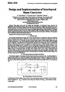
Figure 12 shows the performance presented by the hardware implementation of the Quadrature Oscillator when the frequency of the output signal is exactly equal to one of the FFT’s bin, i.e., the resolution of the FFT used to plot the PSD that in this case is Fsout/M. Power Spectral Density ï PSD SNR = 84.94 dB
SFDR = 89.03 dBc
FFT Noise Floor = 121.07 dB
ï40 Power/Frequency (dB/Hz)
ï120
Number of Slice Registers Number of Slice LUTs Number of occupied Slices Number of LUT Flip Flop pairs used Number of RAMB36E1/FIFO36E1s Number of BUFG/BUFGCTRLs Number of DSP48E1s Fmax (MHz)
ï60 ï80 ï100 ï120 ï140 ï160
Figure 11 shows the comparison between the outputs of the implemented quadrature oscillator and the golden model generated in MATLAB. The oscillation frequency is fo = 3.072 MHz. As mentioned earlier, the quadrature oscillator adopted here is stable, accurate and clear once clarity of the oscillator is crucial to the spectral purity of the DUC output. Oscillator FPGA Implementation Output 5
5 0
X: 3.071e+006 Y: 1.216
ï5
ï5
ï10
ï10 Watts/Hz (dB)
Watts/Hz (dB)
0
Oscillator Golden Model Output
ï15 ï20
ï20 ï25
ï30
ï30
ï35
ï35
ï40
0
0.5 1 1.5 2 Frequency (Hz) x 107
ï40
ï200
0
5
10 Frequency (Hz)
15 6
x 10
Fig. 12. Performance of the Quadrature Oscillator.
The output signal has a frequency of (Fsout/M)*1000 = 3.75 MHz. The Spurious Free Dynamic Range (SFDR) presented by the oscillator with respect to the signal amplitude is equal to 89.03 dBc and it also presents a FFT noise floor of 121.07 dB and SNR of 84.94 dB. For comparison with the Quadrature Oscillator proposed here we present in the sequence the settings and resource utilization of a Xilinx DDS Compiler version 4 synthetized to work at a system clock and output a signal with frequency and SFDR equal to the settings adopted for the Quadrature Oscillator.
ï15
ï25
ï180
0
0.5 1 1.5 2 Frequency (Hz) x 107
Fig. 11. Comparison between the oscillator and its Golden Model.
Table VI presents the summary of the settings adopted for the configuration of the DDS Compiler. The DDS core consists of a Phase Generator and a SIN/COS LUT.
TABLE VI.
SUMMARY OF THE DDS COMPILER SETTINGS
Parameter
TABLE VIII.
RESOURCE UTILIZATION OF THE COMPLEX MULTIPLIER.
Value
Output Width
15 bits
Optimization Goal
Speed
Number of Slice Registers Number of Slice LUTs Number of occupied Slices Number of LUT Flip Flop pairs used Number of RAMB36E1/FIFO36E1s Number of BUFG/BUFGCTRLs Number of DSP48E1s
Phase Width
26 bits
Fmax (MHz)
Frequency Resolution
0.4 Hz
1
System Clock
14 MHz
Frequency per Channel (Fs)
14 MHz
Noise Shaping
Phase Dithering
Memory Type
Block ROM (Auto)
Phase Angle Width Spurious (SFDR)
Free
Range
89 dB
Latency
8
XtremeDSP Slice count
2
BRAM (18K) count
2
Output Signal Frequency
3.072 MHz
Watts/Hz (dB)
RESOURCE UTILIZATION OF THE XILINX DDS COMPILER V4.
Number of Slice Registers Number of Slice LUTs Number of occupied Slices Number of LUT Flip Flop pairs used Number of RAMB36E1/FIFO36E1s Number of BUFG/BUFGCTRLs Number of DSP48E1s Fmax (MHz)
393
301,440
1%
787
150,720
1%
268
37,680
1%
416
0%
1
32
3%
0 216.169 MHz
768
0%
790 0
DUC Golden Model Output
Table VII presents the resource utilization of the Xilinx DDS Compiler version 4 for the settings presented earlier. TABLE VII.
Utilization (%)
Figure 13 presents the comparison between the outputs of the implemented DUC and its golden model generated in MATLAB. As already mentioned, due to the poor attenuation provided by the polyphase filter the spurious peak propagates through the circuit and is up-converted along with the input signal. The spurious peak is 16.814 dB apart from the main peak.
13 bits Dynamic
Available Resources
5
DUC FPGA Implementation Output 5
0
0
ï5
ï5
ï10
ï10 Watts/Hz (dB)
Channels
Used Resources
ï15 ï20
ï15 ï20
Used Resources
Available Resources
Utilization (%)
147
301,440
1%
ï30
ï30
66
150,720
1%
ï35
ï35
53
37,680
1%
ï40
ï40
117
ï25
ï45
1
416
1%
1
32
3%
2 567.859MHz
768
1%
As it can be noticed the Xilinx DDS uses two DSP48 slices and one 36 Kbit Block RAM for the lookup storage. On the other hand, our design only utilizes logic slices, i.e., it is completely implemented in fabric. The oscillator proposed in this work could be easily synthetized on smaller FPGAs containing none or almost none XtremeDSP slices and Block RAMs. It also could be employed in designs running out of those kinds of slice. Table VIII summarizes the resource utilization for the Complex Multiplier when implemented in a Xilinx Virtex-6 XC6VLX240T-1-FF1156 device.
0
0.5 1 1.5 2 7 Frequency (Hz) x 10
X: 3.379e+006 Y: 1.404
ï25
ï45
0
0.5 1 1.5 2 7 Frequency (Hz) x 10
Fig. 13. Comparison between DUC implmentation and its Golden Model.
V.
CONCLUSIONS AND FUTURE WORK
This paper discussed the design and implementation of a DUC using a Xilinx Virtex6 FPGA. It also introduced a new approach for digital oscillators that is easily implemented and consumes a small amount of logic and no XtremeDSP slice and Block RAM. It could be used either in designs synthetized on small FPGAs or designs running out of those kinds of slice. It presents the following performance measures: SFDR of 89.03 dBc, SNR of 84.94 dB and FFT noise floor of 89.03 dB. The main focus of the DUC implementation presented in this work is on giving hints on how to project and implement from scratch employing only FPGA fabric every building block present in a DUC circuit. As future work, some improvements will be applied to the circuit in order to increase its operating frequency. These improvements will take into account the use of DSP48 blocks and the suggestions given in [10] to address timing closure.
Also, as a future work, new tests will be carried out with digitally modulated signals like QAM, PSK, etc. and higher order FIR filters will be employed. REFERENCES [1] [2]
[3]
M. Cummings, S. Haruyama, “FPGA in the Software Radio”. IEEE Communications Magazine, v37, Feb. 1999,pp.108-112. Lin Fei-yu, Qiao Wei-ming, Jiao Xi-xiang, Jing Lan and Ma Yun-hai, “Efficient Design of Digital Up Converter for WCDMA In FPGA Using System Generator", International Conference on Information Engineering and Computer Science (ICIECS), December 2009. Stephen Creaney and Igor Kostarnov, “Designing Efficient Digital Up and Down Converters for Narrowband Systems”, Xilinx Application note for Virtex 5 family, November 21, 2008.
[4]
F. J. Harris, “Multirate Signal Processing for Communication Systems”, Prentice Hall, 2004. [5] Lattice Refrence Design RD1052, “Multi-Channel Digital Up/Down Converter for WiMAX Systems”, April 2009. [6] Altera Application Note 455, “Understanding CIC Compensation Filters”, April 2007. [7] Turner, C., "Recursive Discrete-Time Sinusoidal Oscillators," IEEE Signal Processing Magazine, Vol. 20, No. 3, May 2003, pp. 103–111. [8] Lyons, R., “Understanding Digital Signal Processing”, 2ed, Prentice Hall, 2004. [9] Paillard, B. and Boudreau, A., "Fast, Continuous, Sinewave Generator," GlobalDSP On-line Magazine, Dec. 2003. [10] Xilinx User Guide UG612, “Timing Closure User Guide”, October 2012.