demonstrate an efficient implementation of an Elliptic Curve scalar .... application of Elliptic Curve Cryptosystems is secure key agreement and digital signature.
Submitted to the Twelfth ACM International Symposium on Field-Programmable Gate Arrays, FPGA 2004, Monterey, California, February 22-24, 2004
Implementation of Elliptic Curve Cryptosystems over GF(2n) in Optimal Normal Basis on a Reconfigurable Computer Sashisu Bajracharya1, Chang Shu1, Kris Gaj1, Tarek El-Ghazawi2 1
George Mason University, 2 The George Washington University
Abstract. During the last few years, a considerable effort has been devoted to the development of reconfigurable computers, machines that are based on the close interoperation of traditional microprocessors and Field Programmable Gate Arrays (FPGAs). Several prototype machines of this type have been designed, and demonstrated significant speedups compared to conventional workstations for computationally intensive problems, such as codebreaking. Nevertheless, the efficient use and programming of such machines is still an unresolved problem. In this paper, we demonstrate an efficient implementation of an Elliptic Curve scalar multiplication over GF(2n) in Optimal Normal Basis, using one of the leading reconfigurable computers available on the market, SRC-6E. We show how the hardware architecture and programming model of this reconfigurable computer has influenced the choice of the architectures for all component operations and the overall design of the system. The detailed analysis of the control, data transfer, and reconfiguration overheads is given in the paper, together with the performance comparison of our implementation against the software implementation of the same problem running on a traditional microprocessor. Keywords: Reconfigurable Computer, Elliptic Curve Cryptosystem, Optimal Normal Basis, Projective Coordinates, Multiplicative Inverse, FPGA devices.
1. Introduction Reconfigurable Computers are general-purpose high-end computers based on a hybrid architecture and close system-level integration of traditional microprocessors and Field Programmable Gate Arrays (FPGAs). It is expected that programming of reconfigurable computers should not require any knowledge of hardware design, assuming that sufficiently large library of elementary operations has been earlier developed and made available to end users. The characteristic feature of all reconfigurable computers is that they support run-time reconfiguration, i.e., reconfiguration of FPGA devices during the execution of an application. Whenever an application, running initially on a traditional microprocessor, encounters a function that can be performed more efficiently in hardware, a selected FPGA is reconfigured, and an execution of the function moves to this FPGA. When the function is completed, control comes back to the program running on the microprocessor, and the FPGA becomes available for the execution of the next function. Based on these capabilities, reconfigurable computers constitute a perfect tool for cryptographers and cryptanalysts. These computers support all major features of the specialized hardware, such as parallel processing, distributed memory, specialized functional units (including multiple precision arithmetic units), flexible size and number of registers and buses, high-speed data transfer and embedded memory access. At the same time, all major disadvantages of the specialized machines are eliminated. In particular, there is no cost and very small time penalty for any changes in the algorithms or logic architectures. Additionally, no knowledge of hardware design is required for the efficient use of these computers, as they can be programmed using traditional high-level programming languages. As a result, tremendous savings in terms of the time to the solution and cost of the solution can be accomplished. The emergence of reconfigurable computers offers a great promise in terms of progress in many traditionally hard cryptographic problems. Many of such problems, such as integer factorization, elliptic curve discrete logarithm problem, or counting the number of points on an elliptic curve have been shown in theory to execute substantially more efficiently in hardware [7][34]. At the same time, no prototypes
P3 (1 GHz)
8000 MB/s
4800 MB/s (6x64 bits)
L2
/
L2
8 bits flags
/
800 MB/s
PCI-X
Computer Memory (1.5 GB)
/
/
800 MB/s
/
528 MB/s
800 MB/s
64 bits data
/
MIOC
½ MAP Board
Control FPGA XC2V6000
/
/
8000 MB/s
P3 (1 GHz)
On-Board Memory (24 MB) 4800 MB/s (6x 64 bits)
4800 MB/s (6x 64 bits)
/
µP Board
DDR Interface SNAP
FPGA 1 XC2V6000
/
2400 MB/s (192 bits)
FPGA 2 XC2V6000
(108 bits)
/
/
/ 528 MB/s
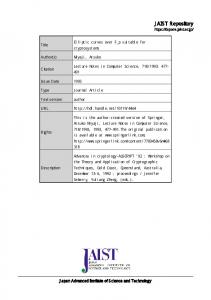
Fig. 1. Hardware architecture of SRC-6E Notation: P3 – Intel Pentium 3 Microprocessor, L2 – Level 2 Cache, MIOC – Memory and I/O Bridge Controller PCI – Peripheral Component Interconnect Interface DDR Interface – Double Data Rate Memory Interface SNAP – SRC-developed Memory Interconnect MAP - Reconfigurable Processor
(108 bits)
Chain Ports
2400 MB/s
Fig. 1. Hardware architecture of SRC-6E
confirming these claims have been reported in the open literature for practical sizes of cryptographic parameters because of the prohibitive cost of specialized hardware. Although a lot of work has been done in the area of reconfigurable computing and run-time reconfiguration, we are aware of only two practical implementations of general-purpose reconfigurable computers. The first is SRC-6E from SRC Computers, Inc. [36], the second HC-36m (and its variants HC62m and HC-98m) from Star Bridge Systems [37]. The first of these machines was chosen for our study. Our goal was not only to confirm the great potential for effective use of reconfigurable computers in cryptography, but also to determine the current and possible future limitations of the reconfigurable computing technology. In particular, the question we were trying to answer was: What is the i/o characteristics and minimum size, latency, and throughput of the functional unit that can benefit from the execution on an FPGA, taking into account the overheads associated with the control, data transfer, and reconfiguration? In order to answer this question, we chose as our benchmark a relatively complex cryptographic operation: scalar multiplication in the group of points on an elliptic curve over GF(2n) with an optimal normal basis representation [9, 11, 17, 32]. This operation is perfect for our goals, as it involves a clear hierarchy composed of four levels of functions. Our goal is to find out, which level functions need to be implemented by a hardware designer as library macros, and at what level the software designer can take over. Our paper gives an answer to this question for the current generation of reconfigurable computers, and provides some predictions on how this answer can evolve in time.
2. SRC Reconfigurable Computer 2.1 Hardware Architecture SRC-6E is a hybrid-architecture platform, which consists of two double-processor boards and one MultiAdaptive Processor (MAPTM) board. A block diagram depicting a half of the SRC-6E machine is shown in Fig. 1. The MAP board includes two User FPGAs, On-Board Memory, and one Control FPGA. All FPGAs included on the MAP board are Xilinx Virtex II XC2V6000 FPGA devices. Each processor board is connected to the MAP board through the so-called SNAP card. An interleaved SNAP card plugs into two DIMM slots on the microprocessor motherboard and can support a peak bandwidth of 800 MB/s. 2.2 Programming Model The SRC-6E has a similar compilation process as a conventional microprocessor-based computing system, but needs to support additional tasks in order to produce logic for the MAP reconfigurable processor, as shown in Figure 2. There are two types of the application source files to be compiled. Source files of the first type are compiled targeting execution on the Intel platform. Source files of the second type are
Application sources
Macro sources
.c or .f files
.vhd or .v files HDL sources .v files
µP Compiler
Main program …… Logic synthesis Netlists
.o files
Function_1
Application executable
a
FPGA
Macro_1(a, b, c) Macro_2(b, d) Macro_2(c, e)
.ngo files Place & Route
……
.bin files Configuration bitstreams
Fig. 2. Compilation process of SRC-6E
Macro_1
c
b Function_2
Linker
FPGA contents after the Function_1 call
Function_1(a, d, e)
MAP Compiler
.o files
Program in C or Fortran
Macro_2
Macro_2
Macro_3(s, t)
Function_2(d, e, f) ……
d
e
Macro_1(n, b) Macro_4(t, k)
Fig. 3. Programming model of SRC-6E
compiled targeting execution on the MAP. A file that contains a program to be executed on the Intel processor is compiled using the microprocessor compiler to produce a relocatable object (.o) file. All files containing functions that call hardware macros and thus execute on the MAP are compiled by the MAP C compiler, mcc, or MAP FORTRAN compiler, mftn. These compilers produce several relocatable object files (.o), corresponding to respective subroutines. Object files resulting from both the Intel and MAP compilation steps are then linked with the MAP libraries into a single executable file. The resulting binary file may then be executed on the SRC-6E Intel and MAP hardware. MAP source files contain MAP functions composed of macro calls. Here, macro is defined as a piece of hardware logic designed to implement a certain function. Since users often wish to extend the built-in set of operators, the compiler allows users to integrate their own macros, encoded in VHDL or Verilog, into the compilation process. The macro is invoked from within the C or FORTRAN subroutine by means of a subroutine call. In Fig. 3, we demonstrate the mapping between macro calls and the corresponding contents of a MAP FPGA. Please, note that Macro 2, called twice in Subroutine 1, results in two instantiations of the logic block representing Macro 2. Values of arguments in the macro calls determine interconnects between macro instantiations in hardware. The contents of each MAP function in software determines the configuration of the entire FPGA device in hardware. Each time a new MAP function is called, the contents of the entire FPGA changes. This way, SRC-6E implements run-time reconfiguration. An application can be implemented either using a single User FPGA, or partitioned among two User FPGAs available on the MAP board. The communication between these two FPGAs is performed using a 192-bit bridge port and auxiliary communication macros.
3. Basic operations of Elliptic Curve Cryptosystems over GF(2n) in Normal Basis Representation Elliptic Curve Cryptosystems (ECCs) are used commonly in constrained environments, such as portable and wireless devices, as a small-area, low-energy alternative to the RSA cryptosystem [5, 14, 33]. The primary application of Elliptic Curve Cryptosystems is secure key agreement and digital signature generation and verification [1, 11, 16, 17]. In both of these applications the primary optimization criterion from the implementation point of view is the minimum latency for a single set of data (rather then the data throughput for a large set of data). The primary operation of ECCs is elliptic curve scalar multiplication. Below we define this operation in terms of lower level operations, and present and contrast several algorithms that can be chosen to perform this operation in hardware.
3.1 Definition of an Elliptic Curve over GF(2n) A non-supersingular elliptic curve over GF(2n) is defined as set of points (x,y) that satisfy the equation, y2 + xy = x3 + a2x2 + a6 , (1) where, x, y, a6 ∈ GF(2n), and a2 ∈ {0,1}, together with the special point called a point at infinity, and denoted as O. The elements of the Galois Field GF(2n) can be represented in several different bases, such as polynomial basis, normal basis, dual basis, etc. In all these representations, addition is the same and equivalent to the XOR operation, but multiplication is defined differently. Our implementation focuses on the normal basis representation [11, 17, 28]. In this representation, each element E=(e0, e1, …, en-1) ∈ n −1 GF(2n) is represented with respect to the basis of the form β , β 2 ,..., β 2 where β ∈ GF(2n) using the following formula n −1
E = ∑ ei β 2 , ei ∈ (0,1) i
(2)
i =0
In the normal basis, squaring in GF(2n) is equivalent to rotation by one position. The remaining operations and the optimum ways of implementing them in hardware are described in Section 5. 3.2 Point Addition and Point Doubling An addition of two points of an elliptic curve P=(xP, yP) and Q=(xQ, yQ), where Q≠-P=(xP, yP+ xP), and P, Q ≠ O is defined in Table 1. Additionally, P+ O = O + P = P, and P + (-P) = O. Similarly, point doubling, 2P=P+P, where P≠ O, is also defined in Table 1. Additionally, 2 O = O. Please, note that outside of special cases, both point addition and point doubling involve two multiplications and one inversion in GF(2n). The remaining operations, such as squaring and addition are normally much less time consuming than multiplication and inversion. Table 1. Formulas for the point addition and doubling for elliptic curves over GF(2n) for basic affine coordinates
Inputs/Output
Point Doubling 2P = R P≠O
Point Addition P+Q = R
P ≠ Q , P ≠ −Q , P, Q ≠ O P : (xP , yP ) Q : ( xQ , y Q ) R : (xR , yR )
Affine + Affine = Affine x R = λ2 + λ + x P + xQ + a 2 x R = x P 2 + a6 λ2 yR = λ ⋅ (xP + xR ) + xR + yP yR = xP 2 + (xP + yP λ)xR + xR yQ + y P 1 λ= λ= xQ + x P xP
# mul = 2 # sqr = 1
# inv = 1 # add = 8
# mul = 3 # sqr = 2
# inv = 1 # add = 4
In normal basis representation, inversion involves a large number of multiplications and therefore it dominates the time of point addition and point doubling. Therefore, an alternative approach is used to speed up the implementation. In this approach, each point P is represented using so called projective coordinates (x, y, z). The conversion between the traditional coordinates, called affine coordinates and projective coordinates is given by the following equations Affine_to_projective (x, y) = (x, y, 1) (3) (4) Projective_to_affine(x, y, z) = (x⋅z-1, y⋅z-1) In projective coordinates, the inversion is eliminated from point addition and doubling at the cost of an increased number of multiplications (15 vs. 2 for point addition, and 7 vs. 2 for point doubling).
3.3 Scalar multiplication
The primary elliptic curve operation used in cryptography is scalar multiplication, defined as kP = P + P + … + P k times
In our implementation of scalar multiplication, we adopted an optimized algorithm for computing scalar multiplication by Lopez and Dahab [27]. Let P ( x, y ) , P1 ( x1 , y1 ) , P2 ( x 2 , y 2 ) (using affine representation) are the points on the elliptic curve, where P2 = P + P1 . It’s known that the x-coordinate of P1 + P2 can be represented with x, x1 , and x2 , and the y-coordinate of P1 can be computed from P and the x-coordinates of P1 and P2 [27]. As a result, only the x-coordinates of the intermediate points needs to be computed when performing scalar multiplication. If the points are represented using projective coordinates, the case is similar, i.e., only x and z coordinates of the intermediate points have to be computed. Let P ( x, y ) , P1 ( X 1 , Z1 ) , P2 ( X 2 , Z 2 ) , where P2 = P + P1 , xi = X i / Z i , P3 = P1 + P2 can be computed using the following formulas: Z 3 = ( X1 ⋅ Z 2 + X 2 ⋅ Z1 ) 2 X 3 = x ⋅ Z 3 + ( X1 ⋅ Z 2 ) ⋅ ( X 2 ⋅ Z1 )
(6)
Thus, only four field multiplications, one squaring and two additions are necessary to complete one point addition. Similarly, for point doubling, P2 = 2 P1 , where X 2 = X 14 + b ⋅ Z14 Z 2 = Z12 ⋅ X 12
(7)
Thus, two field multiplications, four squarings and one addition are necessary to complete one point doubling. The complete algorithm for scalar multiplication is given below as Algorithm 1. The last step of the algorithm 1, involves one inversion, 10 multiplications, 6 XORs, and one rotation. Algorithm 1: Montgomery Scalar Multiplication using Projective Coordinates Input: An integer k ≥ 0 and a point P = ( x, y ) ∈ E. Output: Q = kP.
1. 2.
if k = 0 or x = 0 then output (0,0) and stop. Set k ← (k l−1...k1k 0 ) 2
3. 4.
Set P1 ← ( x,1) , P2 ← ( x 4 + b, x 2 ) for i from l − 2 downto 0 do if ki = 1 then P1 ← P1 + P2 , P2 ← 2P2 else P2 ← P1 + P2 , P1 ← 2P1 Compute the ( xk , y k ) from P1 and P2 (based on formulas given in [27]).
5.
The hierarchy of operations involved in elliptic curve scalar multiplication for the case of elliptic curve over GF(2n) in normal basis representation is given in Fig. 4. Please, note that four levels of operations are involved in this hierarchy, starting from the scalar multiplication, kP, at the top level, down to the GF(2n) multiplication (MUL), squaring (ROT), and addition (XOR) at the bottom level.
High level
kP
Medium level
P+Q
projective_to_affine (P2A)
2P
Low Level 2
INV
Low Level 1
XOR
ROT
MUL
Fig. 4. Hierarchy of the ECC operations
4. Investigated partitioning schemes A hierarchy of operations involved in an elliptic curve scalar multiplication for the case of an elliptic curve over GF(2m) is given in Fig. 4. Four levels of operations are involved in this hierarchy: scalar multiplication, kP, at the high level (H), point addition and point doubling at the medium level (M), inversion at the low level 2 (L2), and the GF(2m) multiplication (MUL), squaring (rotation) (ROT), and addition (XOR) at the lowest level (L1). Functions belonging to each of these four hierarchy levels (high, medium, low 2 and low 1) can be implemented using three different implementation approaches: a) as a C function compiled for a general-purpose microprocessor, b) as a C function compiled by the SRC MAP compiler to the hardware description code running on the User FPGA, and c) as a VHDL hardware macro running on the User FPGA. Two possible extreme cases are to implement scalar multiplication kP entirely in software as a C microprocessor function, or entirely in hardware, using traditional hardware design methodology (i.e., as a VHDL hardware macro, as shown in Fig. 5d). Several intermediate partitioning schemes are possible, and are presented schematically in Figs. 5abc. Each of these approaches is characterized by a three letter codename, such as 0HM. The first letter of this codename determines which level operations (high, medium, low 2, low 1, or none (0)) are implemented in C on a general-purpose microprocessor. The second letter, determines which operations are described as a C function for the MAP, and the third letter, which operations are implemented as HDL macros. a)
0HL1 Partitionin
b)
C function for µP C function for MAP
kP P+Q
P2A
2P
MUL4
c)
C function for µP
H
C function for MAP
INV
VHDL macro
L1 ROT
XOR
MUL2
MUL
VHDL macro
V_ROT
0HM Partitioning
VHDL macro
kP
P+Q
2P
0
kP P+Q
P2A
2P
H P2A
L2 MUL4
d)
C function for µP C function for MAP
0HL2 Partitioning
0
ROT
XOR
MUL2
INV
00H Partitioning
0
C function for µP
0
H
C function for MAP
0
M
VHDL macro
Fig. 5. Four alternative algorithm partitioning schemes
kP
H
For example, the codename 0HM means that no operations are implemented in C for the microprocessor, a high-level operation (kP) is implemented as a C function for MAP, and medium level operations (point addition and doubling) are implemented as VHDL macros. In the 0HL1 scheme, only the lowest level functions (those at the level L1) needs to be implemented in VHDL. In the 0HL2 scheme, the low level 2 function, GF(2n) inversion, is implemented in VHDL, and the majority of the lowest level functions (those at the level L1) are also implemented in VHDL, as they are the components of the medium level operations. In some cases, it appeared to be beneficial to group several instantiations of the same lowest level operation into a single macro. This observation led to the implementation of macros MUL2 and MUL4, shown in Figs. 5ab. These macros implement respectively two and four instantiations of the GF(2n) multiplier. In the most straightforward partitioning approach, HML1, the C MAP function performs in parallel two medium-level operations, P+Q and 2P. The results of both of these operations are returned to kP. Please, note that based on the SRC programming model (explained in Section 2), if P+Q and 2P were implemented as separate high-level MAP functions, then the reconfiguration of the User FPGA would need to take place each time we switch execution between P+Q and 2P. Since the time of the reconfiguration of the User FPGA has been measured to be equal about 48 ms, and kP implemented in VHDL executes within only 200 µs, even a single reconfiguration time by far exceeds the total execution time of kP in hardware. The existence of an integrated P+Q/2P function and calling this function once as a part of the application setup eliminates the reconfiguration overhead. Unfortunately, an additional timing overhead is introduced during each MAP function call because of the control, input, and output transfer between the microprocessor board and the MAP board. In the current generation of the SRC system, this overhead has been measured to be in the range of 390 µs per function call. n-2 such calls would be necessary to complete the entire kP operation. The inferred overhead would be orders of magnitudes larger than the average execution time of the entire kP operation in hardware (in the range of 200 µs). Therefore, this scheme was rejected at the early stage of our analysis. In order to minimize the large overhead of the HML1 scheme, the 0HL1 partitioning scheme (shown in Fig. 5a has been investigated and implemented. In this scheme, the MAP function is called only once and executes the entire high level operation kP. As a result, the control, input, and output overheads occur only once. The kP operation includes point addition, point doubling, and the conversion from the projective to affine coordinates. Point doubling requires a total of two multiplications, which can be done in parallel (see formula (7)). Point addition requires four multiplications in total. However, because of the data dependencies, these multiplications cannot be all performed in parallel, and need to be done in two iterations, with two independent multiplications per each iteration (see Formula (6)). The macros implemented in VHDL include MUL4, MUL2, MUL, ROT, and V_ROT. MUL4 is the macro which includes four multipliers working in parallel. Two of these multipliers are used for point doubling and two for point addition. MUL2 consists of two multipliers working in parallel. It is used in the projective_to_affine (P2A) routine where 10 interdependent multiplications are scheduled using two multipliers, with the maximum possible use of parallelism. MUL is a single multiplier macro used to implement inversion. ROT is a one bit rotation, which is equivalent to squaring in GF(2n) with normal basis. V_ROT is a variable rotation macro used in the inverse operation (INV) in P2A. The primary advantage of the 0HL1 partitioning scheme is that it makes use of only elementary operations in GF(2n), which can either exist in the library, or be implemented using relatively small amount of the hardware designer effort. 0HL2 is similar to 0HL1 except that the inversion (INV) is implemented entirely as a VHDL macro. More hardware code needs to be generated in this case with some performance gain due to manual optimization. A further reduction in the execution time can be accomplished in the 0HM partitioning shown in Fig. 5c, by implementing medium level operations, P+Q, 2P, and P2A as VHDL macros. The disadvantage of this approach is the required hardware knowledge, the level of HDL programming experience and the increased effort necessary to develop VHDL code in place of the C function for the MAP. The advantage is the opportunity for manual optimization of the VHDL code versus the HDL generated by the SRC MAP compiler. This process is analogous to doing assembly coding for the microprocessor. This hardwareoriented approach can be taken to its extreme by implementing the entire kP operation as VHDL macro (see partitioning scheme 00H shown in Fig. 5d.
5. Implementation of Multiplication and Inversion in GF(2n) 5.1 Multiplication
Multiplication in GF(2n) with normal basis representation is defined as follows. For A = (a0 , a1 ,..., a n −1 ) and B = (b0 , b1 ,..., bn −1 ) ∈ GF(2n), the product C = AB = (c0 , c1 ,..., c n −1 ) is given by ck =
n -1
n -1
i= 0
j= 0
∑ ∑
(k )
λ ij
ai bj
The coefficients λ ij(k ) ∈ {0,1} for a specific value of k determine the number of non zero terms aibj in the expression for ck. The number of non-zero terms may very in the range from 2n-1 to n2, depending on the choice of the normal basis. An important mathematical result is that for certain normal bases, the number of non-zero terms reaches its minimum. These bases are called Optimal Normal Bases (ONB) [28]. In our implementation, we focus on the optimal normal bases of Type II. For these bases the coefficients, λ ij(k ) are defined as follows:
λ ij( 0 ) = 1 iff
2 i ± 2 j ≡ ±1 mod 2 n + 1
otherwise λ ij( 0 ) =0, and
λ ij(k ) = λ i(−0 )k , j − k . The minimum number of non-zero coefficients λ ij(k ) translates to the implementation of the GF(2n) multiplier with the minimum area and the minimum number of interconnects [2]. Several different architectures for multiplication in Optimal Normal Basis representation have been proposed [2, 11, 20, 23, 38]. For the purpose of our implementation, we adapted and optimized a multiplier architecture first proposed by Agnew et al. in [2]. This architecture is shown in Fig. 6 for the case of n=5. The input operands are stored in shift registers A and B, the result is generated by cells ci shown in Fig. 6b. In each clock cycle the contents of A, B and C are cyclically shifted right. At the same time, a part of the expression for each coefficient ci is evaluated. After n clock cycles, internal registers of cells ci contain the respective bits of the product C. The critical path in the circuit contains two two-input XOR gates and a single two-input AND gate, plus delays of interconnects and the delay and setup time of a register (see Fig. 6b). The delays of interconnects are reduced by the fact that each cell of register A, ai, is connected to the maximum of four cells ci [2]. As a result, a 100 MHz clock frequency, required from the SRC macros, could be easily accomplished. Additionally, the circuit takes a relatively small amount of area. On the other hand, it requires n clock cycles per GF(2n) multiplication, which is substantially more than the number of clock cycles required for addition and squaring. Our optimization to this basic architecture consisted of reducing the number of clock cycles by a factor of six, while keeping the clock frequency at the level of 100 MHz required by the SRC hardware, and increasing the number of CLB slices by a factor of three. This optimization will be described in detail in a separate publication. a)
b) a0
a1
a2
a3
a4
c0
c1
c2
c3
c4
b0
b1
b2
b3
b4
ai
ci
aj
≡
D
bi
Fig. 6. Multiplier in GF(2n) with normal basis based on [2], n=5
5.2 Inversion
The multiplicative inverse of A ∈ GF(2n) can be computed based on the equation n
n
A −1 = A 2 − 2 = A 2( 2 −1) (6) For the normal basis representation the execution time can be reduced by using a fact that squaring is equivalent to rotation, and thus it takes substantially less time than multiplication. The efficient technique for reducing the number of multiplications has been proposed by Itoh and Tsujii [18]. This technique is based on the recursive dependence 2n-1 - 1 = (2 (n-1)/2 - 1) (2 (n-1)/2 + 1), for n odd 2( (2 (n-2)/2 - 1) (2 (n-2)/2 + 1) + 1), for n even. The way of using this formula to compute inversion is shown below for the case of n=233:
a-1 = a 2(2116 +1) (258 +1) (229+1) Algorithm 2 Multiplicative inverse in GF(2n) ——————————————————— Input: α ∈GF(2n) Output: result = α-1 ——————————————————— 1: flag = 0 2: α = α>>>1 3: k = n-1 4: while (k != 1) do 5: if (LSB(k) = 1) then 6: if (flag = 0) then 7: result = α 8: flag = 1 9: else 10: result = result * α 11: end if 12: α = (α>>>1) * (( α>>>1)>>>(k>>1)) 13: else 14: α = α*(α>>>(k>>1)) 15: end if 16: k = k>>1 17: end while 18: if (flag=0) then 19: result = α 20: else 21: result = result*α 22: end if 23: return result ———————————————————
(1+2(214+1) (27+1) (1+ 2(23+1) (1+2(2+1) ))) )
Itoh Inverter
A (232:0)
233 >>>1
V_ROT
233 bit MUX
K (6:0) 233 bit MUX 233 bit MUX
233
233
233
Register Multiplier 233 >>>1 233 bit MUX 233 bit MUX
Register
-1 A (232:0)
Fig. 8. Block diagram of the inversion unit.
Please, note that each addition in the exponent corresponds to the multiplication, and each power of two corresponds to the multiple square operations (rotations). The algorithm works for any bit length n, and is given above as Algorithm 3. The number of multiplications remains fixed for a particular size of n and is given by I(n) = ⎣log2 (n-1)⎦ + ω(n-1) – 1, where ω(n-1) is the Hamming weight of the binary representation of n-1 [3]. Figure 8 shows the block diagram of the corresponding inversion unit.
6. Design methodology and testing Our implementation supports elliptic curve operations over GF(2n) for n=233, which is one of the sizes recommended by NIST [11]. Additionally, other sizes can be supported by changing the implementation of the GF(2n) multipliers, and the input/output size of other functional units. All hardware macros have been developed first using standard tools for simulation and synthesis of digital circuits, Aldec Active-HDL and Synplicity Synplify Pro. All macros have been optimized to work at the clock frequency of 100 MHz. The XOR operation did not need to be implemented as a user macro, as it is a standard macro in the SRC library. This macro is invoked automatically when compiler encounters the XOR operator (denoted as ‘^’ ) within a C MAP function. Our VHDL implementations have been tested for correct functionality using the public domain software implementations developed by Rosing [32]. The execution time of operations within the C MAP function has been measured in the number of clock cycles using the standard SRC macro, read_timer(). The end-toend time of C functions has been measured in time units using the C timer function of the Linux operating system, gettimeofday().
7. Results The results of the timing measurements for all investigated partitioning schemes are summarized in Table 2. The FPGA Computation Time includes only the time spent performing computations using User FPGAs. The End-to-End time includes the FPGA Computation time and all overheads associated with the data and control transfers between the microprocessor board and the FPGA board. The Total Overhead is the difference between the End-to-End time and the FPGA Computation Time. Two specific components of the Total Overhead listed in Table 2 are DMA Data In Time, and DMA Data Out Time. They represent, respectively, the time spent to transfer inputs from the Common Memory to the On-board Memory, and the time spent to transfer outputs from the On-Board Memory to the Common Memory. Table 2. Results of the timing measurements for several investigated partitioning schemes and implementation approaches
System Level Architecture H00 (Software) 0HL1 0HL2 0HM 00H (VHDL)
End-toEnd Time (µs)
Data Transfer In Time(µs)
FPGA Computat -ion Time (µs)
Data Transfer Out Time (µs)
Total Overhead (µs)
Speedup vs. Software
Slowdown vs. VHDL macro
772,519
N/A
N/A
N/A
N/A
1
1,305
866 863 592
37 37 37
472 469 201
14 14 12
394 394 391
893 895 1305
1.46 1.45 1.00
592
39
201
17
391
1305
1.00
Table 3. Resource utilization for several investigated partitioning schemes and implementation approaches
System Level Architecture Software 0HL1 0HL2 0HM 00H
% of CLB slices (out of 33792) N/A 99 92 75 59
CLB increase vs. pure VHDL
% of LUTs (out of 67,584)
LUT increase vs. pure VHDL
% of FFs (out of 67,584)
FF count increase vs. pure VHDL
N/A 1.68 1.56 1.27 1.00
N/A 57 52 48 44
N/A 1.30 1.18 1.09 1.00
N/A 68 62 39 26
N/A 2.61 2.38 1.50 1.00
On two extremes, Table 2 shows the End-to-End Time for the purely software implementation (Architecture H00), equal to about 770 ms, and the FPGA Computation Time for the purely VHDL implementation (Architecture 00H), equal to about 200 µs. The speed-up by a factor of 3,850 has been demonstrated. It should be noted, that this speed-up could be greater, if we considered throughput (number of scalar multiplications per unit of time), instead of latency, and used all resources available in both User FPGAs for implementation of multiple computational units working in parallel. Additionally, our comparison assumes that the general purpose microprocessor is dedicated entirely to performing cryptographic transformations, which is rarely the case. The scheme that requires the smallest amount of hardware expertise and effort, 0HL1, is still 893 times faster than software and less than 50% slower than pure VHDL macro. Implementing inversion in VHDL, in the 0HL2 scheme, does not give any significant gain in performance and only small reduction in terms of the resource usage. The 0HM scheme is more difficult to implement than 0HL1 and 0HL2 schemes, because of the additional operations that need to be expressed in VHDL Nevertheless, using this scheme gives substantial advantages in terms of both performance (about 45% improvement) and resource usage (e.g., reduction in the number of CLB slices by 24% compared to the 0HL1 scheme).
The most difficult to implement, the 00H scheme (the entire kP operation described in VHDL) appears to have the same speed as 0HM, but it provides an additional substantial reduction in terms of the amount of required FPGA resources. The current version of the MAP compiler (SRC-6E Carte 1.4.1) optimizes performance over resource utilization. As it matures the compiler will be expected to balance high performance, ease of coding, and resource utilization to yield a truly optimized logic.
8. Conclusions We show how the hardware architecture and programming model of SRC-6E has influenced the choice of the architectures for all component operations and the overall design of our benchmark application. We have clearly demonstrated that at the current stage of development of the reconfigurable computers, an intimate knowledge of the system hardware architecture and programming model, and the associated overheads, might be necessary to fully utilize the potential offered by this promising technology. Reconfigurable computers offer a great promise for solving complex cryptographic problems with the speed of specialized hardware and flexibility and productivity of software implementations. In this paper, we describe our experiences with programming one of the leading reconfigurable computers available on the market, SRC-6E. We have chosen as our benchmark the primary operation of Elliptic Curve Cryptosystems over GF(2n) in Optimal Normal Basis representation: scalar multiplication. This operation is particularly challenging for reconfigurable computers, because the primary optimization criterion is latency rather than throughput, and there is only limited amount of parallelism involved in lower level operations, such as point addition and doubling. In spite of these constraints, a significant speed-up in the range of 900-1300 has been demonstrated compared to the public domain microprocessor implementation using four different algorithm partitioning approaches. What is more important however, our study revealed the optimum boundary between hardware and software, and between the descriptions of hardware in VHDL vs. C for the four-level hierarchy of operations constituting the Elliptic Curve scalar multiplication. This boundary had to take into account the trade-off between the end-to-end execution time, the resource utilization, and the designer’s productivity and ability. While the first two criteria are relatively easy to quantify, the third one is more difficult to measure objectively, as it depends strongly on the designer’s skills and background. Additionally, the relative importance and weight of particular criteria might vary depending on particular application and design environment. Assuming as a primary criterion the increased application developer productivity and an attempt to minimize involvement of hardware designers and traditional HDL-based design methodology, we have determined an optimum solution. In this solution, referred to as 0HL1 scheme, the entire scalar multiplication is implemented in hardware, but only low-level operations, GF(2n) multiplication, squaring (rotation) and addition (XOR) needed to be described in VHDL. This partitioning scheme was shown to increase the execution time by less than 50% compared to the scheme based on implementing the entire scalar multiplication in VHDL. This result was accomplished at the cost of the increased use of FPGA resources, such as CLB slices, used mostly as a source of additional flip-flops. Our research demonstrated that a good knowledge of the system hardware architecture and programming model of a reconfigurable computer, and the associated overheads, may be useful to fully utilize the potential offered by this promising technology.
References 1. 2. 3. 4.
Agnew, G. B., Mullin, R. C., Vanstone, S. A.: An Implementation of Elliptic Curve Cryptosystems Over F(2155), IEEE Journal on Selected Areas in Communications, Vol. 11 (1993) 804-813 Agnew, G. B., Mullin, R. C., Onyszchuk, I. M., and Vanstone, S. A.: An Implementation for a Fast Public-Key Cryptosystem, Journal of Cryptology (1991) 3: 63-79 Agnew, G. B., Beth, T., Mullin, R. C., and Vanstone, S. A.: Arithmetic Operation in GF(2m), Journal of Cryptology (1993) 6: 3-13 Ahlquist G. C., Nelson B., Rice M.: Optimal Finite Field Multipliers for FPGAs, Proceedings of the Ninth International Workshop on Field Programmable Logic and Applications, August 1999
5. 6. 7. 8. 9. 10. 11. 12. 13. 14. 15. 16. 17. 18. 19. 20. 21. 22. 23. 24. 25. 26. 27. 28. 29. 30. 31. 32. 33. 34. 35. 36. 37. 38.
Aydos, M., Yanik, T., and Koç, C.: High-Speed Implementation of an ECC-Based Wireless Authentication Protocol on an ARM Microprocessor, in IEEE Proceedings-Communications, vol.148, no.5, p. 273-9, Oct. 2001 Bailey, D. V.: Efficient Arithmetic in Finite Field Extensions with Application in Elliptic Curve Cryptography. J. Cryptology. Vol. 14 (2001) 153-176 Bernstein, D. J., “Circuits for integer factorization: a proposal,” available at http://cr.yp.to/papers.html#nfscircuit Blake, I. F., Gao, S., Mullin, R. C., Vanstone, S. A., and Yaghoobian, T.: Application of Finite Fields, Kluwer Academic Publishers, 1993 Enge, A.: Elliptic Curves and Applications to Cryptography, Kluwer Academic Publishers, 1999 Ernst, M., Jung, M., Madlener, F., Huss, S., and Blümel, R.: A Reconfigurable System on Chip Implementation for Elliptic Curve Cryptography over GF(2n). CHES 2002, LNCS 2523, PP. 381-399, 2003 FIPS 186-2, Digital Signature Standard (DSS), Internet draft, http://csrc.nist.gov/publications/fips/fips1862/fips186-2-change1.pdf, pp. 34-39, 2000, Jan. 27 Gao, S.: Normal Bases over Finite Fields, Ph.D. Thesis, University of Waterloo, Dept. of Combinatorics and Optimization, 1993 Gao, S., Vanstone, S. A.: On Orders of Optimal Normal Basis Generators. Mathematics of Computation. Vol. 64 (1995), 1227-1233 Gao, L., Shrivastava, S., Lee, H., Sobelman, G.: A Compact Fast Variable Key Size Elliptic Curve Cryptosystem Coprocessor. Proc. 7th Annual IEEE Symposium on Field-Programmable Custom Computing Machines, 1998 Guajardo, J., Paar, C.: Itoh-Tsujii Inversion in Standard Basis and Its Application. Cryptography and Codes. Kluwer Academic Publishers (2001) Gura, N. et al.: An End-to-End Systems Approach to Elliptic Curve Cryptography. CHES 2002, LNCS 2523, (2002) 349-365 IEEE P1363 Standard Specifications for Public Key Cryptography, November 1999. Draft Version 13 Itoh, T., Tsujii, S.: A Fast Algorithm for Computing Multiplicative Inverses in GF(2m) Using Normal Bases. Information and Computation. Vol.. 78 (1988), 171-177 Kim, C., Oh S., and Lim, Jongin: A New Hardware Architecture for Operations in GF(2n), IEEE Transactions on Computers v 51 n1 January 2002. p. 90-92 Koç, C. K., Sunar, B.: Low-Complexity Bit-Parallel Canonical and Normal Basis Multipliers for a Class of Finite Fields. IEEE Transactions on Computers, Vol. 47 (1998) 353-356 Kwon, S.: Low Complexity Bit Serial Systolic Multipliers over GF(2m) for Three Classes of Finite Fields. ICICS 2002, LNCS 2513, (2002) 209-216 Kwon, S.: A Low Complexity and a Low Latency Bit Parallel Systolic Multiplier for GF(2m) Using Optimal Normal Basis of Type II, ISCAS 2003 Kwon, S., and Ryu, H., Efficient Bit Serial Multiplication Using Optimal Normal Bases of Type II in GF(2m), ISC 2002, LNCS 2433, pp. 300-308, 2002 Lee C.-H., and Lim J.-I.: A New Aspect of Dual Basis for Efficient Field Arithmetic. IEEE P1363a: Additional number-theoretic algorithm LiDIA. A library for computational number theory, Technical University of Darmstadt. Available from http://www.informatik.tu-darmstadt.de/TI/LiDIA/Welcome.html Lim, C. H., Hwang, H. S.: Fast Implementation of Elliptic Curve Arithmetic in GF(pn). Public Key Cryptography 2000: 405-421 López, J., and Dahab, R.: Fast Multiplication on Elliptic Curves over GF(2m) without precomputation. CHES’99, LNCS 1717, (1999) Mullin, R. C., Onyszchuk, I. M., Vanstone, S. A., Wilson R. M.: Optimal Normal Bases in GF(pn). Discrete Applied Mathematics, Vol. 22 (1988/89), 149-161 Orlando, G., Paar, C.: A High-Performance Reconfigurable Elliptic Curve Processor for GF(2m). CHES 2000, LNCS 1965, (2000) 41-56 Reyhani-Masoleh, A., Hasan, M. A.: Fast Normal Basis Multiplication Using General Purpose Processors. SAC 2001, LNCS 2259, (2001) 230-244 Reyhani-Masoleh, A., Hasan, M. A.: On Efficient Normal Basis Multiplication. INDOCRYPT 2000, LNCS 1977, (2000) 213-224 Rosing, M., Implementing Elliptic Curve Cryptography, Manning, 1999 Schroeppel, R., Beaver, C., Gonzales, R., Miller, R., and Draelos, T.: A Low-Power Design for an Elliptic Curve Digital Signature Chip, CHES 2002, LNCS 2523, pp. 366-380, 2003 Shamir, A., Tromer, E., “Factoring Large Numbers with the TWIRL Device,” Proc. Crypto 2003, LNCS 2729, Springer-Verlag, 2003, http://www.wisdom.weizmann.ac.il/~tromer/ Silverman, J. H.: Fast Multiplication in Finite Fields GF(2N). CHES 1999, LNCS 1717, (1999) 122-134 SRC Inc. Web Page, http://www.srccomp.com/ Star Bridge Systems Web Page, http://www.starbridgesystems.com/ Sunar B., Koc, C. K.: An Efficient Optimal Normal Basis Type II Multiplier. IEEE Transactions on Computers. Vol. 50 (2001), 83-87


![Elliptic Curve over Ring=[];=](https://m.moam.info/img/260x300/elliptic-curve-over-ring_5baf5bd2097c4732688b4779.jpg)