International Conference on Electronics, Computer and Communication (ICECC 2008) University of Rajshahi, Bangladesh
Implementation of low cost Microcontroller based digital RPM meter Khosru Mohammad Salim, Gazi Mohammad Sharif School of Engineering and Computer Science, Independent University, Bangladesh e-mail:
[email protected],
[email protected]
ABSTRACT An RPM meter is a device to measure the number of revolutions a rotating object makes in a minute. In laboratory RPM meter is required in the experiment for speed control of rotating machines. Currently RPM meters needed for industrial applications are imported from abroad and are quite expensive. A low cost RPM meter can be made using a simple 8 bit microcontroller. In this paper we have discussed the design and construction of a microcontroller based RPM meter. We have implemented a low cost RPM meter and the results obtained were very satisfactory which have been presented in the paper.
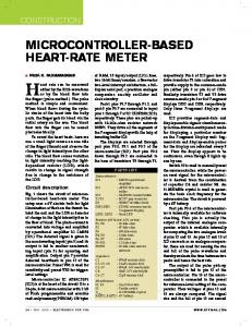
IR sensor used in the project has been shown in Fig.1. Here in this circuit we can control the signal strength by increasing-decreasing the resistance used in series with the transmitter hence we can increase or decrease the range between the reflective object and the sensor. The light signal is received by Infra-Red LED, converting it to current. An Op-Amp is used to get a TTL signal (High or Low) depending of the presence and absence of the reflector.
KEY WORDS: RPM meter, Microcontroller, Low cost, Contact less, Infrared sensor 1. INTRODUCTION In industries, RPM that is the number of revolutions in a minute of a rotating machine is important. Many production processes need this, for example power generation facilities need RPMs of turbines in order to calculate how much power is being generated [1]. The first form of RPM meters were mechanical and were based on measuring the centrifugal force of the rotating object. A German engineer Didrich Uhlhorn is considered to be the inventor of the RPM meter in 1817 [2]. Since 1840 it has been primarily used to measure the speed of locomotives. These meters have come a long way and now can be developed by using of sensors and microcontrollers. The use of microcontroller in the design of RPM meters has made it possible to reduce costs, because the components needed to construct the meter are cheap and locally available in Bangladesh. Currently the industries are importing RPM meters which are quite expensive. It is possible to make such a device locally at a cheaper cost. We have developed a RPM meter that uses a microcontroller (PIC16F84A) using a Infrared transmitter and sensor that transmits and receives signals using a spot placed on the rotating object that reflects light. The meter which we developed is a non-contact type RPM meter [3]. 2. HARDWARE DESIGN This project consists of three major units; sensor unit, control unit and display unit. Sensor unit consists of Infra-Red transmitter and receiver. Infra-Red (IR) transmitter transmits light to the air and if it is reflected from a shiny object to the receiver, the receiver conducts current. The schematic circuit diagram of the
ISBN 984-300-002131-3
Fig. 1: Circuit diagram of IR sensor
Fig. 2: Circuit diagram of the control unit with the four seven segment LED display The heart of the RPM meter is an 8 bit microcontroller. We used PIC16F84A microcontroller from Microchip Corporation in our project. This microcontroller has total 13 I/O ports which are enough for this job, we need only 12 ports. We can directly connect the seven segment LED display to its ports because the ports have sufficient driving current. We used multiplexing technique in driving the 4 display units; therefore we need total (7+4) 11 I/O ports for display driving, 7 ports for segment driving and 4 ports for selecting digits. One
634
International Conference on Electronics, Computer and Communication (ICECC 2008) University of Rajshahi, Bangladesh
additional port is used for connecting with the sensor unit. A 4 MHz clock resonator has been used as a system clock for the controller where it is possible to use a clock frequency up to 20 MHz. The main circuit diagram of the controller and display unit has been drawn in Fig. 2. 3. SOFTWARE DESIGN We have written the program in MPLAB an integrated development environment (IDE) for Microchip’s microcontroller [4]. The software of the RPM meter consists of three main units; sensing rotating object, performing math for rpm calculation and displaying the data in seven segments formats. The flowchart of the program has been shown in Fig. 3. Since PIC 16F84A is a RISC (Reduce Instruction Set Computer) processor it has only 35 instructions. We write the code in assembly language. 3.1 Method of RPM calculation We programmed the timer unit of the microcontroller in such a way that it can calculate time in 1 ms step very accurately. When an object rotates, the sensor gets pulses from the reflector attached to the rotating object. The sensor unit is connected the microcontroller through pin RB0 (6). The microcontroller is interrupted if it gets pulse from the sensor. Then it counts the total number of time steps from the timer unit between the two successive interrupts from the sensor. From that time it can calculate the RPM of the rotating device using following formula. RPM = 60,000/ number of time steps (1) Where 1 minute = 60,000 ms The basic building blocks of the code have been described in the following steps; 1. Start 2. Initialize register, timer, IR detector 3. If {IR detector (1) Detect light} Start clock. Else Return IR detector (1) 4. If {IR detector (2), Detect spot depth} Stop clock Else Return IR detector (2) 5. Calculate RPM 6. Display 7. Return IR detector (1) 8. Continue.
ISBN 984-300-002131-3
Fig. 3: Flowchart of the algorithm 4. RPM METER CONSTRUCTION AND EXPERIMENTAL RESULTS We have constructed the IR sensor in a aluminum pipe where we used coaxial cable for connecting it to the microcontroller unit in order to avoid electromagnetic interference. The picture of the contracted sensor is shown in Fig. 4. The prototype of the RPM meter is shown in Fig. 5. We have tested the meter in the laboratory for calculating the RPM of a small cooling fan and have compared it with the value obtained from a industry grad RPM meter. Our meter gives the same value at lower RPM (200rpm or less) however, at higher rpm it defers from its industrial counterparts. This is because; we used 1 ms time step in calculating time which is much higher. We need to reduce the time step for getting better accuracy in high rpm calculation.
Fig. 4: IR sensor constructed in a aluminum pipe.
635
International Conference on Electronics, Computer and Communication (ICECC 2008) University of Rajshahi, Bangladesh
Fig. 5: Testing the RPM meter in measuring the rpm of a small cooling fan. 5. CONCLUSIONS We have designed and constructed a low cost microcontroller based RPM meter for industrial application. We made the prototypes of both the sensor using IR transmitter and receiver and the RPM meter using 8 bit microcontroller. We tested the meter and gets satisfactory results. However, at high rpm calculation regulation can be improved by introducing lower time step.
ISBN 984-300-002131-3
References [1] Ansari, S.A.; Baig, R, “A pc based vibration analyzer for condition monitoring of the process machinery” IEEE Transaction on Measurement and Instrumentation, vol. 47, no. 2 pp. 378– 383, April. 1998. [2] Ambrus, D. Bilas, V. Vasic, D, “A digital tachometer for high-temperature telemetry utilizing thermally uprated commercial electronic components” IEEE Transaction on Measurement and Instrumentation, vol. 54, no. 4 pp. 1361–1365, Aug. 2005. [3] Atmanand, M.A. Kumar, V.J. Murti, V.G.K “A microcontroller-based quasi-balanced bridge for the measurement of L, C and R” IEEE Transaction on Measurement and Instrumentation, vol. 45, no. 3 pp. 757–761, Jan. 1996. [4] www.microchip.com
636