866
IEEE TRANSACTIONS ON MICROWAVE THEORY AND TECHNIQUES, VOL. 58, NO. 4, APRIL 2010
Low-Cost FPGA Implementation of Volterra Series-Based Digital Predistorter for RF Power Amplifiers Lei Guan, Student Member, IEEE, and Anding Zhu, Member, IEEE
Abstract—This paper presents a low-complexity and low-cost hardware implementation of a Volterra series-based digital predistorter (DPD). This is achieved by introducing two novel model complexity reduction techniques into the system, namely, lookup table assisted gain indexing and time-division multiplexing for multiplier sharing. Experimental results show that this novel DPD implementation uses much less hardware resources, but still maintains excellent performance compared to conventional approaches. Index Terms—Linearization, lookup table (LUT), power amplifier (PA), predistorter, Volterra series.
I. INTRODUCTION
W
ITH THE goal of simultaneously achieving high efficiency and high linearity, digital predistortion techniques along with methods for memory effect compensation have been proposed to linearize RF power amplifiers (PAs). Examples include techniques based on memory polynomials [1], [2], Hammerstein and Wiener models [3], augmented Wiener model [4], nonlinear auto-regressive moving average (NARMA) model [5], etc. The principle of the digital predistorter (DPD) is simple: a nonlinear distortion function is built up within the digital domain that is the inverse of the distortion function exhibited by the amplifier. A highly linear and low distortion system can be achieved in principle when these two nonlinear systems, the DPD and PA, are combined in series. An attraction of this approach is that the nonlinear PA can be linearized by a standalone add-on block, freeing vendors from the burden and complexity of manufacturing complex analog/RF circuits [6]. Previously, an efficient DPD for RF PAs was proposed in [7]. This DPD approach is derived from the dynamic deviation reduction-based Volterra series [8], which allows simultaneous compensation for nonlinear distortion and memory effects with
Manuscript received October 26, 2009; revised January 12, 2010. First published March 08, 2010; current version published April 14, 2010. This work was supported by the Science Foundation Ireland under the Principal Investigator Award Scheme. The authors are with the School of Electrical, Electronic and Mechanical Engineering, University College Dublin, Dublin 4, Ireland (e-mail:
[email protected];
[email protected]). Color versions of one or more of the figures in this paper are available online at http://ieeexplore.ieee.org. Digital Object Identifier 10.1109/TMTT.2010.2041588
a small number of parameters. Based on the th-order post-inverse theory, the parameters of this DPD can be directly estimated from the measured input and output of the PA with a simple offline characterization process. This eliminates the requirement for real-time closed-loop adaptation, and removes the necessity to implement the parameter estimation algorithms in real digital circuits, which significantly reduces system complexity and implementation cost. Experimental results showed that this truncated Volterra DPD model can achieve superb performance in linearizing various types of RF PAs. However, only the model structure and system characterization methodology were introduced in [7], The DPD algorithm was just implemented in a software environment, e.g., MATLAB, and important issues related to practical hardware implementation were not discussed. Although it may look straightforward, different methodologies or implementation structures will lead to very different results in terms of complexity and cost from the viewpoint of hardware implementation. In this paper, we present a low-complexity and low-cost solution for hardware implementation of this advanced DPD technique using real digital circuits. This is achieved by introducing two novel model complexity reduction techniques in the system, namely, the lookup table (LUT) assisted gain indexing and time-division multiplexing for multiplier sharing. Since the field programmable gate array (FPGA) has many advantages in digital signal processing, including high density integration, parallel operation mechanisms, high-speed processing (DSP), and flexible implementation, the FPGA has become one of main choices for implementing baseband DPDs for RF PAs. In this study, we illustrate how to implement the proposed Volterra DPD model on FPGA chips, but the proposed technique is not solely limited to FPGAs. The same structure can also be readily implemented in other types of digital circuits, e.g., general DSP chips or application-specific integrated circuits (ASICs). This paper is organized as follows. In Section II, we briefly reintroduce the proposed Volterra DPD system. Section III presents details of hardware implementation of the DPD. The experimental results are given in Section IV with a conclusion presented in Section V. II. DPD ALGORITHM With the rapid development in DSP techniques, most predistorters today are implemented in the digital baseband. In these systems, the original baseband signals are first predistorted by
0018-9480/$26.00 © 2010 IEEE Authorized licensed use limited to: University College Dublin. Downloaded on April 13,2010 at 05:50:34 UTC from IEEE Xplore. Restrictions apply.
GUAN AND ZHU: LOW-COST FPGA IMPLEMENTATION OF VOLTERRA SERIES-BASED DPD FOR RF PAs
Fig. 1. Block diagram of digital predistortion.
a digital predistortion unit and then passed through a digital-toanalog converter (DAC), up-converted to RF frequency, and finally passed to the PA. In order to extract and update the coefficients of the DPD, a small fraction of the transmit signal is fed back and transferred to baseband via a down-converter and an analog-to-digital converter (ADC). The model parameter extraction unit compares the input and the output captured data, and extracts the coefficients for the DPD. This model extraction unit is normally only operational during the initial setup of the system or whenever the characteristics of the system are changed. The block diagram of a baseband digital predistortion system is illustrated in Fig. 1. In [7], the dynamic deviation reduction-based Volterra model is used for constructing the DPD function. For instance, the firstorder dynamic truncation of the Volterra model can be written as
867
posed DPD structure must be implemented in transmitters with very low cost. However, direct implementation of the DPD function, i.e., (1), requires a large number of multipliers and adders to construct the nonlinear and memory terms. For example, 60 . This number multipliers will be needed when become larger. Since the increases significantly when and multiplier is one of the most complex and expensive components in FPGA hardware,1 the large number of multipliers required dramatically increases system complexity and the final cost of the DPD system. III. NEW DPD IMPLEMENTATION In this paper, we seek an alternative and efficient way to implement this Volterra DPD, as discussed in the following. A. LUT-Assisted Gain Indexing From (1), we can see that the number of multipliers required mainly results from the generation of the power and the memory terms, and their multiplications with the coefficients. However, if we rewrite (1) as
(2) where (3)
(1) where and are the input and the output in-phase/ is the comquadrature (I/Q) envelopes, respectively; represents the complex plex Volterra kernel of the DPD, returns the magnitude. is the conjugate operation, and order of nonlinearity and represents the memory length. Only odd-order nonlinearities are included in this baseband representation in (1), i.e., is an odd number, since the effects from even-order kernels can be omitted in a band-limited modulation system. The implementation of this DPD system mainly includes two parts, which are: 1) the DPD unit, which predistorts the input I/Q signal and 2) the parameter extraction unit, which is used to initialize and update the coefficients. In [7], by employing the th-order post-inverse theory [9], the coefficients of the DPD can be estimated from the measured input and output of the PA with an offline characterization process. The model extraction unit can thus be implemented in a software environment, which can be embedded in general DSP circuits in the system. Although both units, the DPD and parameter extraction, must be implemented efficiently in the system, the most critical part centers on implementing DPD unit itself. Since real-time online signal processing is required, the DPD unit must be implemented in high-speed digital hardware circuit, e.g., FPGAs or ASICs. As price pressures become ever more demanding, in order to make it feasible and competitive in the market, the pro-
(4) we can find that, for a given memory tap and can be considered as a constant complex gain to or , respectively, while or depends only since on polynomial power terms of or is a constant for each power term after model extraction or in time-invariant operations when is fixed. Furthermore, in a real system, even if the individual samples of the and are randomly generated, the range of signal the input signal is normally known in advance. This means that , it is possible to calculate the high-order power terms of and thus, the values of and in advance, and store them in a table and retrieve them later. For example, if the is normalized maximum value of the input magnitude to unity and the LUT size is 1024, the interval value for the and LUT, , will be 1/1024. A set of values of for each interval can be calculated in advance. For example, can be obtained by adding all power terms for and multiplying with the coefficients together for each given interval values, as shown in Fig. 2. In the same way, similar and , tables can be built for different memory taps for . These values can then be retrieved where is directly from the tables when a specific input value of given. Using this approach, only two LUTs are required 1[Online].
Available: http://www.xilinx.com
Authorized licensed use limited to: University College Dublin. Downloaded on April 13,2010 at 05:50:34 UTC from IEEE Xplore. Restrictions apply.
868
IEEE TRANSACTIONS ON MICROWAVE THEORY AND TECHNIQUES, VOL. 58, NO. 4, APRIL 2010
Fig. 2. Example of LUT contents.
for the whole system, and this number no longer increases with the nonlinear order since all higher order terms can be built in one table, no matter how many orders there are. , only the memory terms One may note that from (2), for are separated out and all other terms are built into the LUT; while is also left outside the table along with the for is a conjugated memory terms. This is because the input complex number including I and Q values, but the LUT address is generated from the magnitude only, with the same magnitude can have different values since value, the power term may have different phases for each sample, which leads that one address can correspond to multiple output values. To avoid must be left outside the LUT for , this problem, although this requires two more multipliers to implement the system. This LUT mapping approach is more efficient than a direct polynomial-based implementation of (1) since it no longer requires multiplication between input samples to produce the power terms. This structure also eliminates the requirement for building separate tables for each nonlinear power terms, as is the case in traditional LUTs [10]–[12]. Consequently, the hardware resource requirement for the DPD is significantly reduced. Furthermore, unlike most conventional LUT-based DPDs where the gain values are often obtained directly through curve fitting between input and output data, which often leads to low accuracy, in this approach, an analytical function-based model, i.e., the truncated Volterra series, is employed to represent the characteristics of the DPD and a least squares algorithm is utilized to extract the coefficients. This allows us to accurately control the nonlinear order and the memory length to be compensated for, and guarantees high accuracy in the model and , extraction. Although during the calculation of high precision signal processing is required to produce accurate results, e.g., producing high-order power terms, this does not affect the final LUT structure because the intermediate values are calculated offline in a software environment and they are not and are stored in the LUTs. Only the final results of stored in the LUTs. The precision requirement for these final values are much lower than that required for the intermediate terms, and therefore, they can be easily scaled to suit a small LUT size, significantly saving memory storage in the DPD chip. In summary, this proposed approach takes advantages of the best features of both analytical function- and LUT-based solutions, which are: 1) high accuracy in model extraction is
Fig. 3. DPD implementation example.
maintained by using an analytical function-based DPD model, while 2) complexity and cost in hardware implementation is reduced by the LUT. The next step of the implementation is to include the memory , and the terms left outside the terms, i.e., LUTs, . One solution is to multiply the values retrieved from the LUTs with these terms by using multipliers. For example, an implementation of the first part of the output is shown in Fig. 3. This is similar to the “Basic Predistortion Cell” structure proposed in [13], but only one address index is needed to retrieve the values from LUTs in this case because the power terms in all LUTs are the same, in other words, they all . Multiple coonly depend on the instantaneous samples ordinate rotation digital computers (CORDICs) [14] are, therefore, avoided, which can further save hardware resources. B. Time-Division Multiplexing for Multiplier Sharing Compared to direct analytical function based DPDs or conventional LUT approaches, the complexity and cost of the implementation shown in Fig. 3 have been dramatically reduced. However, this structure is not the simplest one because a large number of multipliers are still involved, and this number will increase with the memory length. To further reduce the complexity, time-division multiplexing can be employed as described below. In Fig. 3, multipliers are operated in parallel and each operation occupies an entire time slot. However, if we convert the parallel operation to a serial operation (for example, by using a multiplexer), all multiplication operations can be conducted in a serial way with one multiplier. The time sequence of these operations is shown in Fig. 4. Transforming from parallel to serial processes, the time duration for each operation becomes shorter, which requires that the original data must be up-sampled and the signal processing needs to be conducted in a higher speed. The block diagram is shown in Fig. 5, where the of this implementation of original data are up-sampled first and a multiplexer is then used
Authorized licensed use limited to: University College Dublin. Downloaded on April 13,2010 at 05:50:34 UTC from IEEE Xplore. Restrictions apply.
GUAN AND ZHU: LOW-COST FPGA IMPLEMENTATION OF VOLTERRA SERIES-BASED DPD FOR RF PAs
869
Fig. 4. Time sequence view of multiplication operations.
Fig. 6. Proposed DPD implementation. Fig. 5. DPD implementation using multiplexing.
to redistribute the data for conducting the multiplication operations serially. At the end of operations, the output data are recombined and down-sampled back to the original sampling rate to produce the final output. The details of each composite block are given as follows. 1) Input Up-sampling: this block increases the operation frequency by a factor of with data repeating units, i.e., the input data are repeated times at a higher sampling rate. 2) Input Magnitude Calculation: The CORDIC algorithm [14] is used to calculate the magnitude of input complex I/Q data, and this is used in conjunction with a chip-selection (CS) signal as the address for the LUTs. 3) LUT Mapping: Separated LUTs are mapped into different parts of a standalone RAM on board so that indexing the contents is easier; the LUTs parts are indexed with the magnitude of respective input signals and the multiplexed CS signal. This saves the hardware cost for implementing addressing buses. Each LUT contains two parts: one for storing the real part of the coefficients and the other for the imaginary part. 4) Data Multiplexing: This part contains a multiplexer with a delay units, and each delay unit selection signal CS and delays time cycles, This structure converts parallel multiplications using multiple multipliers to serial operations sharing only one multiplier. 5) Complex Multiplication (CM): The symbol in Fig. 5 represents the CM, which is used to conduct multiplication between the output of MUX and the value retrieved from LUTs. 6) Output Accumulation (ACC): This block is used to implement the ACC operation, which is used to compensate for the memory effects distortion.
7) Output Down-sampling: Not all the results obtained from the accumulator are useful for producing the final output of the DPD; some values are just the intermediate processing results, which can be discarded. The output is only time cycle in the serial data obtained from every sequences. Thus, a down-sampling block is employed to conduct such “selection.” , can be implemented The second part of the DPD, using a similar structure as in Fig. 5, and with another two comterm. Combining the two plex multipliers to include the parts, and , together with proper delays to compensate processing delays between two branches, we can form the final structure of the DPD, as shown in Fig. 6. In this structure, only four complex multipliers are required in total, and the number of multipliers used does not increase with the memory length or the nonlinearity order . This significantly reduces the cost of the system, especially for the systems with long-term memory effects or high-order nonlinearities. Furthermore, in [7], in order to further reduce the system complexity, under-sampling and interpolation were used. The original input and output signals are sampled with a low sampling rate (lower than the Nyquist rate) at the model extraction stage, while the input signal is then up-sampled and the parameters are interpolated by inserting zeros to avoid aliasing effects at the implementation stage. As such a case, the DPD function (1) becomes
Authorized licensed use limited to: University College Dublin. Downloaded on April 13,2010 at 05:50:34 UTC from IEEE Xplore. Restrictions apply.
(5)
870
IEEE TRANSACTIONS ON MICROWAVE THEORY AND TECHNIQUES, VOL. 58, NO. 4, APRIL 2010
where is the over-sampled input and the new output of the DPD. is the ratio of the sampling rate required for DPD output signal reconstruction versus that of the under-sampled model extraction data. Equation (5) can be easily implemented with the same structure as Fig. 6, where only the duration of the time delay in each delay unit of the multiplexers needs to be to . This proposed structure changed from can also be easily adopted to implement the memory polynomial or other truncated Volterra-series-based DPD models, although that is outside the scope of this paper. IV. RESULTS In order to validate the proposed DPD implementation, an experimental test bench was set up in which the RF chain is the same as that presented in [7], where the baseband I/Q signal is first modulated to a digital IF and then converted to the analog domain and up-converted to the RF band, and finally sent to the PA. To capture the output data, the output of the PA was first down-converted to the IF band, and then converted to the digital domain and finally demodulated to the baseband. The core digital predistortion function was implemented on a Xilinx Virtex-4 XC4VSX35 FPGA chip and the model parameter extraction was conducted in MATLAB.
Fig. 7. Sample waveform errors in the time domain.
A. System Performance Evaluation The performance of this truncated Volterra-series-based DPD model has already been tested and presented in [7]. To avoid repetition, in this paper, we only focus on evaluating the accuracy of the hardware-implemented DPD compared to the software-implemented one in [7], i.e., comparing the output predistorted by the hardware DPD with the one produced by the software DPD when given with the same input. To facilitate this comparison, the same PA and signal source were used as in [7], where a high-power gallium–nitride (GaN) amplifier was operated at 1.94 GHz, and excited by a wideband code division multiple access (WCDMA) signal with a chip rate at 3.84 MHz and with 9.57-dB peak-to-average power ratio (PAPR). The WCDMA I/Q samples were recorded with a low sampling rate at 15.36 MHz for parameter extraction, and the input signal was then over-sampled by a factor of four to a sampling rate at 61.44 MHz in the final system to avoid aliasing. Equation (5) with was implemented on the FPGA board. The nonlinearity order was chosen as 7 and memory length . There were 32 parameters in total. It required four complex multipliers [one for and three for ] and nine and four for ) to implement the DPD LUTs (five for function of (5). The size of the LUTs was 1024, and each LUT had 32-bit storage capacity, in which low 16 bit was for the real part values and high 16 bit for the imaginary part. The import and export dual data port RAMs were 32 bit in width and 8640 in size. For system validation, the data processed by the FPGA was captured from the hardware platform and compared with the results produced in the ideal software environment MATLAB. 2000 samples per set and 20 sets of independent data samples were recorded and compared. The normalized mean square errors (NMSEs) are depicted in Fig. 7, where we can see that the average error is around 66 dB. This indicates that the FPGA hardware implementation produced a very high precision for
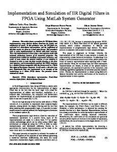
Fig. 8. Spectra plots of the system with and without DPD.
the signals. We then passed the predistorted signal through the whole RF chain. As expected, with the DPD, the nonlinear distortion was almost completely removed. The adjacent channel power ratios (ACPRs) in both the first and second adjacent channels were reduced to under 60 dBc and the normalized root mean square error (NRMSE) was reduced to 1.8%. The output spectrum of the PA was almost identical with that produced by the software-implemented DPD, as shown in Fig. 8. Tests with other PAs and signals also produced similar results, as presented in [7]. B. Comparison of Different Implementations For comparison, two other DPD structures were also implemented, which were: 1) Scheme 1 (S1) is the direct structure, in which the DPD function is directly implemented by using the multipliers and adders and 2) Scheme 2 (S2) is the structure, as shown in Fig. 3, in which the coefficients and nonlinear power terms are built into LUTs while the memory terms are implemented by using multipliers. The proposed structure in which the coefficients and nonlinear power terms are built into LUTs
Authorized licensed use limited to: University College Dublin. Downloaded on April 13,2010 at 05:50:34 UTC from IEEE Xplore. Restrictions apply.
GUAN AND ZHU: LOW-COST FPGA IMPLEMENTATION OF VOLTERRA SERIES-BASED DPD FOR RF PAs
TABLE I HARDWARE UTILIZATION COMPARISON
871
compared to conventional approaches. The benefit of the proposed approach will become more evident when the FPGA implementation is transformed to standalone integrated circuits or ASICs for mass production. V. CONCLUSION
TABLE II FPGA RESOURCE UTILIZATION COMPARISON
while the memory terms are implemented by using shared multipliers with time-division multiplexing is referred to as Scheme 3 (S3). The hardware utilization for different nonlinear orders and memory lengths for three schemes above are shown in Table I, and the LUT represents complex multipliers, twowhere input adders, and LUTs, respectively. It can be clearly seen that the cost of Scheme 1 is highest and its complexity significantly increases with the nonlinear order or the memory length. The number of multipliers is reduced in Scheme 2, but it increases with the memory length. Scheme 3 uses much fewer resources and the number of multipliers is the same for all systems with different nonlinear orders and memory lengths, which provides significant benefit when the nonlinear order and the memory length increase. The resource utilization difference between three schemes becomes more evident when implementing this DPD on an FPGA board. Table II shows the Xilinx FPGA resource utilization in implementing the three schemes for the nonlinear order and memory length . It can be seen that the proposed scheme use much fewer resources on the board, especially the DSP48 slices, which are dedicated high-performance signal-processing blocks. By employing multiplexers and conducting serial operations, times the system clock in the proposed scheme must be higher than those in the parallel processing, such as in Scheme 1 and 2. This does not create a problem for digital circuits since the clock rate of digital chips is continuously pushing higher, for example, 600-MHz signal processing capability is currently available in Xilinx Virtex-6. The price of such chips is continuously falling. However, although significant improvements have been made over the last decades, the complex multipliers are still complicated to implement, requiring dedicated DSP slices and occupying a large area of silicon chip. The number of these special designed DSP units, e.g., DSP48, is limited on FPGA boards. Therefore, by employing the LUT and multiplexing combined approach, the implementation structure of the DPD is much simpler and the overall cost will be much lower
A new technique for implementing Volterra series-based DPDs for RF PAs has been proposed in this paper. By combining LUT and multiplication, together with time division multiplexing, the hardware resource required by the implementation is significantly reduced, and therefore, the cost of the system is dramatically lowered. This DPD can be easily implemented on programmable FPGA boards or made as a standalone integrated circuit chip, and used for linearizing various types of RF PAs. Due to the very simple structures involved, this digital IC can be made at very low cost in a single unit; however, by adding such a linearization module, the PA in the transmitter can be driven to saturation to produce much high power, but without introducing severe distortion. Compared to conventional transmitters employing linear amplifiers, this saturated nonlinear PA plus DPD structure can be much more power efficient and a great deal less expensive to implement, which is very attractive for future wireless communications. REFERENCES [1] J. Kim and K. Konstantinou, “Digital predistortion of wideband signals based on power amplifier model with memory,” Electron. Lett., vol. 37, no. 23, pp. 1417–1418, Nov. 2001. [2] L. Ding, G. T. Zhou, D. R. Morgan, Z. Ma, J. S. Kenney, J. Kim, and C. R. Giardina, “A robust digital baseband predistorter constructed using memory polynomials,” IEEE Trans. Commun., vol. 52, no. 1, pp. 159–165, Jan. 2004. [3] V. J. Mathews and G. L. Sicuranza, Polynomial Signal Processing. New York: Wiley, 2000. [4] T. Liu, S. Boumaiza, and F. M. Ghannouchi, “Pre-compensation for the dynamic nonlinearity of wideband wireless transmitters using augmented Wiener predistorters,” in Proc. Asia–Pacific Microw. Conf., Suzhou, China, Dec. 2005, vol. 5, pp. 4–7. [5] G. Montoro, P. L. Gilabert, E. Bertran, A. Cesari, and D. D. Silveira, “A new digital predictive predistorter for behavioral power amplifier linearization,” IEEE Microw. Wireless Compon. Lett., vol. 17, no. 6, pp. 448–450, Jun. 2007. [6] P. B. Kennington, High Linearity RF Amplifier Design. Norwood, MA: Artech House, 2000. [7] A. Zhu, P. J. Draxler, J. J. Yan, T. J. Brazil, D. F. Kinball, and P. M. Asbeck, “Open-loop digital predistorter for RF power amplifiers using dynamic deviation reduction-based Volterra series,” IEEE Trans. Microw. Theory Tech., vol. 56, no. 7, pp. 1524–1534, Jul. 2008. [8] A. Zhu, J. C. Pedro, and T. J. Brazil, “Dynamic deviation reductionbased Volterra behavioral modeling of RF power amplifiers,” IEEE Trans. Microw. Theory Tech., vol. 54, no. 12, pp. 4323–4332, Dec. 2006. [9] M. Schetzen, The Volterra and Wiener Theories of Nonlinear Systems, reprint ed. Malabar, FL: Krieger, 2006. [10] P. Jardin and G. Baudoin, “Filter lookup table method for power amplifier linearization,” IEEE Trans. Veh. Technol., vol. 56, no. 3, pp. 1076–1087, May 2007. [11] P. L. Gilabert, A. Cesari, G. Montoro, E. Bertran, and J.-M. Dilhac, “Multi-lookup table FPGA implementation of an adaptive digital predistorter for linearizing RF power amplifiers with memory effects,” IEEE Trans. Microw. Theory Tech., vol. 56, no. 2, pp. 372–384, Feb. 2008. [12] L. Rexberg, “Power amplifier pre-distortion,” U.S. Patent 2006/ 0133536, Jun. 22, 2006. [13] A. Cesari and P. L. Gilabert, “A FPGA based digital predistorter for RF amplifiers with memory effects,” in Proc. 2nd Eur.. Microw. Integrated Circuits Conf., Munich, Germany, Oct. 2007, pp. 135–138. [14] Y. H. Hu, “CORDIC-based VLSI architectures for digital signal processing,” IEEE Signal Process. Mag., vol. 9, no. 3, pp. 17–34, Jul. 1992.
Authorized licensed use limited to: University College Dublin. Downloaded on April 13,2010 at 05:50:34 UTC from IEEE Xplore. Restrictions apply.
872
IEEE TRANSACTIONS ON MICROWAVE THEORY AND TECHNIQUES, VOL. 58, NO. 4, APRIL 2010
Lei Guan (S’09) received the B.E. and M.E. degrees in electronic engineering from the Harbin Institute of Technology, Harbin, China, in 2006 and 2008, respectively, and is currently working toward the Ph.D. degree at University College Dublin, Dublin, Ireland. He is currently with the RF and Microwave Research Group, University College Dublin. His research interests include linearization and system-level modeling of RF/microwave PAs with emphasis on digital predistortion and FPGA hardware implementation based on Volterra series. He also has interests in wireless system design and DSP.
Anding Zhu (S’00–M’04) received the B.E. degree in telecommunication engineering from North China Electric Power University, Baoding, China, in 1997, the M.E. degree in computer applications from the Beijing University of Posts and Telecommunications, Beijing, China, in 2000, and the Ph.D. degree in electronic engineering from University College Dublin (UCD), Dublin, Ireland, in 2004. He is currently a Lecturer with the School of Electrical, Electronic and Mechanical Engineering, UCD. His research interests include high-frequency nonlinear system modeling and device characterization techniques with a particular emphasis on Volterra-series-based behavioral modeling for RF PAs. He is also interested in wireless and RF system design, DSP, and nonlinear system identification algorithms.
Authorized licensed use limited to: University College Dublin. Downloaded on April 13,2010 at 05:50:34 UTC from IEEE Xplore. Restrictions apply.