First, we explain how to add a newly developed cleaning function to our robot system. Second, we ... implemented successfully, many developed software modules such as maps ..... its own intelligence. The Robot Knowledge Management.
Implementation of Multi-Functional Service Robots Using Tripodal Schematic Control Architecture Gunhee Kim, Woojin Chung, Munsang Kim, Chongwon Lee Intelligent Robotics Research Center Korea Institute of Science and Technology 39-1 Hawolgok-dong, Sungbuk-ku, Seoul, 136-791, Korea { knir38, wjchung, munsang, cwlee }@kist.re.kr Abstract - This paper describes the implementation of multifunctional service robots using the Tripodal schematic control architecture. Our strategy has two major advantages. First, the proposed architecture supports Petri net based formal description of tasks and error/fault handling schemes. Second, it provides intuitive and straightforward guidelines of system integration issues. We show reusability and scaleability of the proposed architecture by giving two examples of our experience. First, we explain how to add a newly developed cleaning function to our robot system. Second, we introduce the implementation process of a newly developed guide robot Jinny. Most of modules developed for former robots are used directly to the Jinny system. Experimental results clearly showed that the developed strategy is efficient and easy-to-use. Index Terms - control architecture, service robots, Petri nets, object-oriented programming
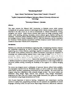
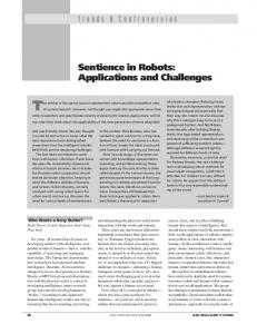
I. INTRODUCTION The PSR (Public Service Robot) systems have been developed towards indoor service tasks at the KIST (Korea Institute of Science and Technology). So far, we have built three versions of the PSR systems, PSR-1, PSR-2, and a guide robot Jinny, as shown in Fig.1. Also, we implemented four target service tasks, a delivery, a patrol, a guide and a floor cleaning task. The aim of the project is to develop intelligent multi-functional robots in large-scale indoor environments.
(a) PSR-1
(b) PSR-2 Fig. 1 Three PSR systems.
(c) Jinny
It is essential to develop well-defined control architecture in our applications for several reasons. First, as the application domains are expanded and the number of robot platforms increases, the functional performance of each module becomes highly dependent on the architecture. Second, the reconfiguration of components frequently takes places as implemented tasks increase. For example, if a delivery task is
implemented successfully, many developed software modules such as maps, localization, and path planners can be directly reused for a cleaning task. That is, a new task can simply be carried out by developing only a few modules newly and reconfiguring them with existing components. In our previous work [1], we proposed the Tripodal schematic control architecture as the solution to this problem. We successfully conducted a delivery task in which a robot shifted a target object from one room to another room in actual human coexisting environment. We used several stateof-the-art navigation and manipulation technologies, which include Monte Carlo localization and path planning in a dynamic environment, as well as an object-picking process based on visual servoing technique. There have been many related research activities so far. It is a recent trend that many control architectures converge to a similar structure based on hybrid approach that integrates reactive control and deliberation [3][4][5][6][7][8]. Our strategy has two major advantages over pervious researches. First, the proposed architecture supports Petri net based formal description of tasks and error/fault handling schemes. Second, it provides three types of diagrams as easyto-use and straightforward guidelines of system integration issues. The integration process is intuitively completed by just following the proposed procedures. The scope of this paper is to show practical advantages of the proposed architecture by giving two examples of our experiences. First, we explain how to add a new cleaning function using Tripodal schematic approach step-by-step. The proposed architecture provides some crucial organizing principles and core components as the infrastructure of the system. Thus, the newly developed behaviors and planning algorithms is systematically integrated without loss of generality. Second, we describe how to develop a new guide robot Jinny using Tripodal schematic approach. Most of modules developed for previous platforms are reused directly. Chapter II briefly introduces the Tripodal schematic control architecture. Chapter III shows the extensibility of the architecture through the process of addition of a new cleaning functional ability. Chapter IV presents the reusability of the architecture by introducing the porting process from the existing control program to a newly-developed platform. Chapter V illustrates the results of experiments in order to show the efficiency of the Tripodal architecture. Finally, some concluding remarks are given in Chapter VI.
II. OVERVIEW OF TRIPODAL SCHEMATIC CONTROL ARCHITECTURE The point of Tripodal schematic design is to integrate robot systems by using following three frameworks shown in Fig. 2. The detailed description of whole control architecture of the PSR is introduced in [1].
Our wall following algorithm is developed in order to minimize the number of times of turning and total moving distance. If the robot turns too often, the cleaning time grows longer due to frequent occurrence of acceleration and deceleration. The total moving distance should be reduced in order to decrease the cleaning time and energy consumption. Through the simulations, it is proved that our approach is superior to other existing algorithms like distance transform and plowing method [10]. Another advantage of our algorithm is robustness with respect to the odometry error since it generates velocity commands based on raw sensing data in every sampling time. From section B to section D, we will explain how to use three diagrams of the architecture in detail. B. Component arrangement using layered functionality diagram
Fig. 2 The overview of Tripodal schematic control architecture.
1) Layered functionality diagram: It is a conceptual diagram for arrangement of various hardware and software modules and functions. It also shows the connectivity and the information flow between components 2) Class diagram: For modularity and reusability, it is designed for implementing various types of software modules with UML [9]. It represents association and hierarchy relation between components. 3) Configuration diagram: It is a Petri net based configuration design for the planning part of a robot considering error recovery logics. III. ADDING A NEW CLEANING TASK USING TRIPODAL SCHEMATIC CONTROL ARCHITECTURE A. Scenario of a new cleaning task The new cleaning task is performed as follows. Initially, the grid map of a target workspace is loaded. And then, it is divided into several sections if it is a too large open space. Sweeping the whole space in several sections is more efficient than cleaning it at one process since the former is less affected by localization errors and uncertainties of environments. Each section is swept by the full-coverage cleaning algorithm based on the wall following technique. This method guarantees the robot smoothly moves with a fixed distance to the wall using a laser range finder. If the robot goes round the wall, the distance between the robot and a wall increases. The robot repeats these steps until the assigned workspace is fully covered. Then, the robot moves to the nearest section to be cleaned. These processes iterate alternately until the whole workspace is covered.
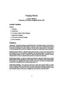
Fig. 3 Layered functionality diagram.
As shown in Fig. 3, the layered functionality diagram is composed of three layers, which are deliberate layer, sequencing layer, and reactive layer based on hybrid approach. The deliberate layer has the function of interfacing with a user and executing planning process. The reactive layer consists of the real-time control command generators and hardware-related modules for sensors and actuators. The sequencing layer is classified into two groups. The first group is the controlling part, the process supervisor and low-level configuration, which executes an internal process by supervising the components in the reactive layer. The second group, navigation modules and manipulations modules, is the information part that assists the planning process or extracts highly advanced information from raw sensor data. The planner, the process supervisor, configurations, and the behavior coordinator in Fig. 3 are core components that are used to build the basis for our architecture. The other parts can be added or replaced for better performance.
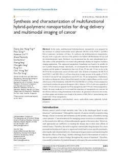
motion commands in a very short time. Therefore, it is implemented as the behavior BhCleaning. The last step is to define the input and output relations between new modules and existing components. The pull/push and synchronous/asynchronous relations is also considered. The section splitter loads the local grid map of the workspace from maps in the navigation modules firstly. The division criterion is the existence of isolated obstacles, which is the object not connected to the wall. The section splitter sets the virtual wall between two nearby sections, and generates the section set. Then, the planner with high-level configuration makes process lists based on the section set. Fig. 5 shows the input and output relations between the section splitter and other modules.
Fig. 4 The guideline for the arrangement in Layered functionality diagram.
Integration by using layered functionality diagram is divided into three steps. First, we specify what modules or algorithms should be newly developed in order to accomplish a target task. Then, we determine where new modules are located in the layered functionality diagram. Finally, we define the input and output relation with other modules. In the case of the cleaning task, three modules are necessary such as a section splitter, a cleaning algorithm, and a moving algorithm. The moving algorithm has been already implemented in the former delivery task as the form of process PrAutoMove[1][2]. The PrAutoMove is our fundamental navigation strategy that integrates a shortest collision-free path planer and a Monte Carlo localizer. Therefore, the section splitter and the cleaning algorithm should be newly developed. Next step is to determine the location of these two modules in the layered functionality diagram. Fig. 4 shows the guideline for these arrangement problems. Since the layered functionality diagram defines architectural requirements of each component, the location is decided uniquely by following the flow chart. The section splitter provides the information about how to divide the workspace. It is used to decide the sequence of the PrAutoMove and the cleaning process. That is, the section splitter assists planning process; therefore, it is located in the navigation modules. Our cleaning algorithm is not so time-consuming, and generates
Fig. 5 Input / output relations between the section splitter and other modules.
As shown in Fig. 6, the BhCleaning initially loads a section of the local grid map assigned to the current cleaning process from the maps. The behavior also takes some processrelated parameters such as the position of the virtual wall from the process supervisor. In every sampling time, the robot receives the current position from the localizers and raw laser data from the laser resources, and sends mobile commands to the behavior coordinator. The behavior reports its states to the process supervisor in the form of events such as the error and fault detection or the completion of the behavior.
Fig. 6 Input / output relations between the BhCleaning and other modules.
C. Implementation using Class diagram
“carry the document box from room 2111 to 2133.” The task is carried out by sequence of process modules in series. The process module consists of one process, fault recovery logics, and all necessary information. The process is defined as a job which is performed by supervising reactive components. The result of the process is definitely divided into success or failure in order to ensure the initial plan is achievable. Each process also encapsulates the network of behaviors, error recovery logics, and related parameters. The behavior is a primitive action that can be executed in very short time. The proposed architecture has two types of the configuration, high-level configuration and low-level configuration, according to the level of layers as shown in Fig.3. The planner decomposes a task to the list of process modules by referring high-level configuration while the process supervisor breaks down a process into several of behaviors by help of low-level configuration.
Fig. 7 Class diagram.
The class diagram is designed in order to implement various types of software modules. It represents association and hierarchy relation between components by following UML standard [8]. The class diagram does not have important theoretical meaning, but it is defined with two practical reasons. First, the structure of the PSR control program is so complicated that it contains more than 600 classes. Second, it is necessary that several developers and new comers can modify or add their components without affecting other modules. Thus, the class diagram is used to describe the structure of software architecture understandably. The software architecture is coded in C++ using an object-oriented approach. The class diagram resembles the layered functionality diagram since each component of the layered functionality diagram is encapsulated as a class. The section splitter is implemented as a CSectionSplitter. It is initiated by CNaviModules. Class diagram also specifies class inheritance hierarchy for reusability and consistency. For example, CBhCleaning is inherited from CBehavior that defines all common properties and requirements of behaviors. Thus, thus developers can make a new behavior through simple modification of a few derived functions. D. Task decomposition using Configuration diagram In our architecture, planning is realized in the form of the configuration. It has two functions. One is to describe task decomposition, and the other is to define error and fault recovery logics. Configuration diagram is designed by using Petri nets, one of the widely used formal languages. Petri nets are advantageous for the design of configurations for several reasons [7]. The task decomposition is divided into three levels, which are a task, a process, and a behavior in our architecture. The task given by a user is a job which should be autonomously performed by the robot. It includes a delivery, a patrol, a guide and a floor cleaning tasks in our applications. It is given in form of quite simple command like “Clean the room 3211” or
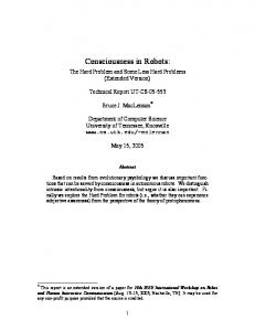
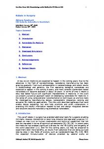
Fig. 8 Petri net model of process module of PrCleaning in high-level configuration. TABLE I DESCRIPTION OF PLACES AND TRANSITION OF FIG.8 PL/TR
Description
P0 P1 (P2)
Standby. Executing (Completing) the process PrCleaning. State: The behavior BhCleaning fails due to disagreement between the map and actual environment. Fault: The full coverage is failed due to inaccurate map information. (due to a localization fault) Planner starts (completes) the process PrCleaning. Process supervisor (PS) posts fault message “disagreement between the map and actual environment” Planner decides to go on next process in spite of failure of full coverage. Planner decides to do same process again. PS posts fault message “a localization fault.”
P3 P4 (P5) t0 (t1) t2 t3 t4 t5
As mentioned before, the newly added cleaning function is performed by iterating the process modules of PrAutoMove and PrCleaning. Fig. 8 and Table I shows the Petri net model of the process module of PrCleaning in high-level configuration. If the process ends up successfully, that is, the token is assigned to the P2 in Fig. 8, then, the next process module starts. Otherwise, the planner reorganizes the existing list of process modules. In the model of PrCleaning, two types of fault are considered. One is the localization fault, and other is disagreement between the grid map and actual environment. If the robot loses its way, the planner inserts the global localization process module in order to find out where it is. If the grid map is not in accord with the actual environment, the
robot decides whether the disagreement results from dynamic objects or not. If the answer is “yes,” the robot does same process again. Otherwise, it just goes over next process module. Fig. 9 and Table II describe the Petri net model of the process PrCleaning in low-level configuration. It consists of places representing behavior execution, internal states and faults. For example, if the error event is transmitted from the localizer and the error state is not temporary, the token is moved to the fault place, P6 in Fig. 9. Then the failure is reported to the high level configuration. This corresponds to t5 in Fig. 8 and Table I. The Petri net models and descriptions of the PrAutoMove can be shown in [7].
behaviors and sends them to the controller. The controller transmits the commands to the hardware motion board in every sampling time. This control loop performs very quickly in real time, 100 ms in our systems. Several control loops can simultaneously exist according to the number of the controllers in a single system. Most of components developed for the PSR-1 and the PSR-2 are reused directly. Because of the generality and scaleability of this structure of the reactive layer, only hardware-related modules such as the controller has changed one to one.
Fig. 10 Data flow in reactive layer. Fig. 9 Petri net model of process PrCleaning in low-level configuration. TABLE II DESCRIPTION OF PLACES AND TRANSITION OF FIG.9 PL/TR
Description
P0 P1 (P4)
Standby. Executing (Completing) the behavior BhCleaning. State: Normal localization. (Localizer updates a robot position periodically.) State: Abnormal localization. (Localizer doesn’t update a robot position, and robot navigates only by using odometry.) Fault: The behavior BhCleaning fails due to disagreement between the map and actual environment. (Due to a localization fault.) PS starts (completes) the behavior BhCleaning. Localizer finds out the estimated position is (NOT) accord with the actual robot position. PS terminates the behavior BhCleaning due to inaccurate map information. (Due to a localization fault.)
P2 P3 P5 (P6) t0 (t3) t1 (t2) t4 (t5)
IV. IMPLEMENTATION OF A NEW GUIDE ROBOT USING TRIPODAL SCHEMATIC CONTROL ARCHITECTURE A. Hardware-dependent modules In this section, we describe the reusability of our architecture by introducing a new guide robot Jinny. The hardware configuration of Jinny is quite different from that of former systems, PSR-1 and PSR-2. For example, the PSR-1 and PSR-2 have holonomic omni-directional mechanisms while the Jinny has a two-wheel differential mobile base. Also, Jinny is equipped with a completely different type of servo controllers to reduce fabrication cost. Fig. 10 shows the structure of the reactive layer in our architecture. The behaviors generate the control command by using raw sensor data from the resources. The behavior coordinator fuses the control commands from one or more
B. Human Robot Interface (HRI) In the development of the guide robot Jinny, we place more weight on the HRI, which receives a task command and displays the internal states of a robot. Table III describes the interaction element of the HRI in Jinny system. The inputs to the HRI are classified into two types, a reactive input and a command input. The reactive input means the user’s request which can be archived by the HRI alone. For example, it includes simple dialogs such as “Introduce yourself.” or “How’s weather today?” The command input is the user’s order which should be performed by the planning process. That is, the command input, like a delivery and a cleaning task, needs activations of other components. In order to handle the reactive input, the HRI should have its own intelligence. The Robot Knowledge Management System (RKMS) undertakes this role. It specifies the connection between reactive inputs and appropriate responses. The RKMS extracts some key words from the inputs through receptive elements. Then, it searches the results with the highest similarity in its knowledge base. It also applies to the recognition of natural language. The RKMS has a userfriendly graphic user interface, and it uses widely-known web authoring language XML so that developers can easily extend robot’s knowledge. TABLE III THE INTERACTION ELEMENTS OF THE HRI IN JINNY SYSTEM - Voice recognition Receptive - Touch screen elements - 12 LED buttons - Voice synthesizer - Screen (displays animated agents, pictures, and Expressive videos) elements - Gestures (using mobile base, 2-DOF neck system, and two 1-DOF arm system)
V. EXPERIMENTS AND RESULTS A. A cleaning experiment
Fig. 13 The guide robot Jinny in the exhibit hall of Hyundai Heavy Industries. Fig. 11 The map of a workspace and the result of coverage of Section C.
Fig. 12 PSR-2 in cleaning experiments.
The developed cleaning task is implemented and tested on the PSR-2 platform. In this experience, we went through little architectural burden for adding a new task through previously mentioned procedures using three diagrams. Fig. 11 shows the map of a workspace whose size is about 10m × 32m. The workspace is divided into four sections by virtual walls. Therefore, four times of PrCleaning and several times of PrAutoMove are necessary to complete a cleaning task of the given workspace. The number of execution of PrAutoMove and the order of these processes are changed according to the robot’s initial position. The experimental workspace is constructed with boxes on a reduced scale of the actual target environment, the exhibit hall of Hyundai Heavy Industries. The results of coverage motion in the section C is also presented in Fig. 11. Fig. 12 shows the PSR-2 in cleaning experiments. B. The guide robot Ginny The Tripodal schematic control architecture is successfully implemented into the newly developed guide robot Jinny. It takes less than a week to port control program of PSR systems into new hardware system. The Jinny was demonstrated at the 2003 Korea Science Festival from August 13th to 17th. Also, it was tested in the exhibit hall of Hyundai Heavy Industries as shown in Fig. 13. The Jinny autonomously navigated the environment and explained 25 exhibits to visitors. It performed several interesting service jobs in response to user’s requests. For example, it played a simple game with visitors, and danced to the music. Also, it provided the information about today’s weather and stock quotations gathered from the web sites.
VI. CONCLUSION This paper addressed our experience about the development of PSR systems using the Tripodal schematic control architecture. In this paper, we showed practical advantages of the proposed architecture through our experiences. First, we explained how to add a new cleaning task using Tripodal architecture approach step-by-step. Then, we introduced the implementation of the guide robot Jinny to prove the reusability and scaleability of our architecture. Experimental results clearly showed that the developed strategy is useful for both extending robot’s ability and developing a new platform. REFERENCES [1] Gunhee Kim, Woojin Chung, Munsang Kim, and Chongwon Lee, “Tripodal Schematic Design of the Control Architecture for the Service Robot PSR,” in Proceeding of the IEEE Conference on Robotics and Automation, Taipei, Taiwan, pp.2792-2797, 2003. [2] Woojin Chung, Gunhee Kim, Munsang Kim, and Chongwon Lee, "Integrated Navigation System for Indoor Service Robots in Large-scale Environments ", Proceedings of the 2004 International Conference on Robotics and Automation, New Orleans, LA, 2004. [3] Erann Gat, Three-Layer Architectures in D. Kortenkamp et al. eds. Artificial Intelligence and Mobile Robots, AAAI Press, MA: 1998. [4] R. C. Arkin, Behavior-Based Robotics, The MIT Press, MA: 1998. [5] Reid G. Simmons, “Structured Control for Autonomous Robots,” IEEE Trans. on Robotics and Automation, vol. 10, no. 1, pp. 34-43, February 1994. [6] Sebastian Thrun, Maren Bennewitz, Wolfram Burgard, Armin B. Cremers, Frank Dellaert, and Dieter Fox, “MINERVA: A SecondGeneration Museum Tour-Guide Robot,” in Proceeding of the IEEE Conference on Robotics and Automation, Detroit, Michigan, USA, pp. 1999-2005, 1999. [7] Mattias Lindstrom, Anders Oreback, and Henrik I. Christensen, “BERRA : A Research Architecture for Service Robots,” in Proceeding of the IEEE Conference on Robotics and Automation, San Francisco, CA, USA, pp. 3278-3283, 2000. [8] R. Volpe, I. Nesnas, T. Estlin, D. Mutz, R. Petras,and H. Das, "The CLARAty architecture for robotic autonomy," in Proceedings of the IEEE Aerospace Conference, MT, pp. 121- 132, March 2001. [9] G. Booch, J. Rumbaugh, I. Jacobsen, “Unified Modeling Language User Guide,” Addison Wesley, Longman, 1997. [10]Joon Seo Oh, Jin Bae Park; Yoon Ho Choi, “Complete coverage navigation of clean robot based on triangular cell map,” in IEEE International Symposium on Industrial Electronics , Pusan, South Korea , pp. 2089 - 2093, 2001.