RESEARCH ARTICLE 25. J. D. Kirkpatrick et al., Astron. J. 120, 447 (2000). 26. G. Basri et al., Astrophys. J. 538, 363 (2000). 27. Ya. Pavlenko, M. R. Zapatero Osorio, R. Rebolo, Astron. Astrophys. 355, 245 (2000). 28. S. J. Wolk, thesis, State Univ. of New York at Stony Brook, Stony Brook, NY (1996). 29. A. G. A. Brown, E. J. de Geus, P. T. de Zeeuw, Astron. Astrophys. 289, 101 (1994). 30. I. Baraffe, G. Chabrier, F. Allard, P. H. Hauschildt, Astron. Astrophys. 337, 403 (1998). 31. G. Chabrier, I. Baraffe, F. Allard, P. H. Hauschildt, Astrophys. J. Lett., in press. 32. F. D’Antona and I. Mazzitelli, Astrophys. J. Suppl. Ser. 90, 467 (1994).
33. R. J. White, A. M. Ghez, I. N. Reid, G. Schultz, Astrophys. J. 520, 811 (1999). 34. K. L. Luhman, Astrophys. J. 525, 466 (1999). 35. W. H. Warren and J. E. Hesser, Astrophys. J. Suppl. Ser. 36, 497 (1978). 36. G. Basri and E. L. Martı´n, Astron. J. 118, 2460 (1999). 37. A. Burkert, M. R. Bate, P. Bodenheimer, Mon. Not. R. Astron. Soc. 289, 497 (1997). 38. A. P. Boss, Science 276, 1836 (1997). 39. P. Bodenheimer, Astron. Soc. Pac. Conf. Ser. 134, 115 (1998). 40. We are indebted to I. Baraffe and the Lyon group for providing theoretical evolutionary tracks prior to publication. We also thank A. Burrows for facilitating an electronic version of his models. We are grateful to C.
Gutie ´rrez and J. Licandro for taking data necessary for calibrating some of the K images, and to C. Koresko for making available NIRC spectra of some of the reference objects. This paper is based on observations made with the 2.5-m Isaac Newton Telescope operated on the island of La Palma by the Isaac Newton Group at the Observatorio del Roque de los Muchachos of the Instituto de Astrofı´sica de Canarias, the Keck I and Keck II telescopes on the Mauna Kea Observatory, the 2.2- and 3.5-m telescopes on the German-Spanish Calar Alto Observatory, the 1.5-m Carlos Sa ´nchez telescope on the Teide Observatory of the Instituto de Astrofı´sica de Canarias, and the 3.8-m UKIRT telescope on the Mauna Kea Observatory. 6 July 2000; accepted 7 September 2000
REPORTS
Optically Defined Multifunctional Patterning of Photosensitive Thin-Film Silica Mesophases Dhaval A. Doshi,1 Nicola K. Huesing,3 Mengcheng Lu,1 Hongyou Fan,1,5 Yunfeng Lu,4 Kelly Simmons-Potter,5 B. G. Potter Jr.,5 Alan J. Hurd,5 C. Jeffrey Brinker1,2,5* Photosensitive films incorporating molecular photoacid generators compartmentalized within a silica-surfactant mesophase were prepared by an evaporation-induced self-assembly process. Ultraviolet exposure promoted localized acid-catalyzed siloxane condensation, which can be used for selective etching of unexposed regions; for “gray-scale” patterning of refractive index, pore size, surface area, and wetting behavior; and for optically defining a mesophase transformation (from hexagonal to tetragonal) within the film. The ability to optically define and continuously control both structure and function on the macro- and mesoscales is of interest for sensor arrays, nanoreactors, photonic and fluidic devices, and low-dielectric-constant films. The ability to pattern porous thin films is important for a number of technological applications, including sensor arrays, optics, and microfluidic devices. Mesoporous silicas (1) are attractive for such applications because they have internal connectivity and variable density that can be tailored by preparative conditions. Soft lithographic approaches (2) have been used to pattern mesoporous films but require long processing times (3, 4) or have been limited to physically defining the presence or absence of dis1 Department of Chemical and Nuclear Engineering and Center for Micro-Engineered Materials, Advanced Materials Laboratory, University of New Mexico, 1001 University Boulevard SE, Albuquerque, NM 87106, USA. 2Department of Chemistry, University of New Mexico, Albuquerque, NM 87131, USA. 3Institute of Inorganic Chemistry, Vienna University of Technology, Vienna, Austria. 4Applied Materials, Santa Clara, CA 95054, USA. 5Sandia National Laboratories, Albuquerque, NM 87185, USA.
*To whom correspondence should be addressed. Email:
[email protected]
crete isolated regions (3, 4). Rapid patterning of organofunctionalized mesoporous thin films by means of pen lithography, ink-jet printing, and selective dewetting has also been demonstrated recently (5), but to date no one has successfully patterned thin-film mesostructure or properties. Here we report patterning of the mesostructure within a thin film. Our procedure uses evaporation-induced self-assembly to prepare a photosensitive thin-film mesophase containing a photoacid generator (PAG). We then exploit the pH sensitivity of both the siloxane condensation rate and the silica-surfactant self-assembly process to optically define film location, mesostructure, and properties. The procedure begins with a homogeneous solution of silica, surfactant, PAG (a diaryliodonium salt), and HCl (6), with initial acid concentration designed to minimize the siloxane condensation rate (7, 8). Preferential ethanol evaporation during dip- or spin-coating (9) concentrates the depositing solution in water and nonvolatile constituents, thereby promoting self-assembly
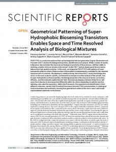
(10, 11) into a photosensitive, one-dimensional hexagonal (1-dH) silica-surfactant mesophase. Because it bears a long-chain hydrocarbon, the PAG serves as a cosurfactant during the assembly process, which promotes its uniform incorporation within the mesostructured channels of the 1-dH film. Irradiation of the PAG at a maximum wavelength (max) of 256 nm (reaction 1) results in homolytic or heterolytic photodecomposition to yield the Brønsted superacid, H⫹SbF6–, plus an iodoaromatic compound and organic byproducts (12). Thus ultraviolet (UV) exposure of the photosensitive mesophase through a mask creates patterned regions of differing acid concentrations compartmentalized within the silica mesophase (Fig. 1). Co-incorporation of a pH-sensitive dye (ethyl violet) allows direct imaging of these patterned regions as in Fig. 2A, where the yellow (exposed) and blue (masked) regions correspond to pH 0 and pH 2, respectively (13). Suppression of the siloxane condensation rate during film deposition enables several modes of optically mediated patterning. Because acid generation promotes siloxane condensation, selective UV exposure results in patterned regions of more and less highly condensed silica (14). Differential extents of siloxane condensation result in turn in differential solubility, allowing selective etching of more weakly condensed regions in aqueous base (0.2
Reaction 1
www.sciencemag.org SCIENCE VOL 290 6 OCTOBER 2000
107
REPORTS M NaOH) (scheme 1 of Fig. 1). An optical micrograph of a UV-exposed and etched thinfilm mesophase after calcination to remove the
surfactant templates (Fig. 2B) reveals that the film is present only in the exposed regions. The plan-view transmission electron microscopy
Fig. 1. Processing pathways for optically defined multifunctional patterning of thin-film silica mesophases. Conc., concentration; irr, irradiated; unirr, unirradiated.
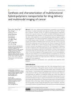
Fig. 2. Optical patterning of function and properties in thin-film silica mesophases. (A) Optical image of localized acid generation via co-incorporation of a pH-sensitive dye (ethyl violet). The blue areas observed on the unexposed film correspond to pH* ⱖ 2.0, and the yellow areas observed on the exposed film correspond to pH* ⬃ 0 (where pH* refers to the equivalent aqueous solution pH required to achieve the same colors). (B) Optical micrograph of a UV-exposed and selectively etched mesostructured thin film (after calcination). Feature size ⬇ 10 m. Inset: TEM image of the film seen in (B), consistent with the [110] orientation of a 1-dH mesophase with lattice constant a ⫽ 37 Å. (C) Optical interference image showing thickness and refractive index contrast in a patterned calcined film. The green areas correspond to UV-exposed and calcined regions and the black areas to unexposed and calcined regions. (D) Optical image of an array of water droplets contained within patterned hydrophilic-hydrophobic corrals. Water droplets sit on hydrophilic regions with contact angle ⬍10° and are bounded by the hydrophobic UV-exposed regions with contact angle ⫽ 40°.
108
(TEM) image (Fig. 2B, inset) reveals a striped mesoscopic structure consistent with a 1-dH mesophase with unit cell size a ⫽ 37 Å. We have also used a C3F8 plasma to directly etch the unexposed regions of photopatterned films (15). This process could potentially eliminate the need for a photoresist in the patterning of mesoporous low-dielectric-constant films needed by the microelectronics industry (16). Organic by-products of the ( patterned) PAG photodecomposition process render UV-exposed regions of the film hydrophobic (contact angle ⫽ 40°) relative to adjoining unexposed regions (contact angle ⬍10°). This differential wetting behavior is evident in Fig. 2D, where a patterned, square hydrophilic lattice serves to corral water into an array of monosized droplets. Such corrals can be used to selectively derivatize hydrophilic regions with aqueous-based reagents (17) and/or biomolecules. A second aspect of our approach is the optical definition of film mesostructure and associated structure-related properties such as pore size, pore connectivity, and refractive index (Fig. 2C). Depending principally on the type and concentration of surfactant, we can produce two contrasting types of behavior. As depicted in schemes 2 and 3 of Fig. 1, if we heat the patterned film, we obtain adjoining regions of differing refractive index where the sign of the refractive index contrast ⌬n may be either positive (nirradiated ⬎ nunirradiated) or negative. Both types of behavior result from a greater extent of siloxane condensation in the UVexposed regions. For positive ⌬n, the UV-exposed regions are still hexagonal but are denser than unexposed regions. We used a cantilever beam technique (18, 19) to measure the development of condensation-induced, thin-film, biaxial tensile stress and found that the differing extent of siloxane condensation was UV-dose– dependent. Therefore, by spatially varying the UV exposure using grayscale lithography, we can pattern continuous variations in the film refractive index and thickness, as well as in the structural properties of the 1-dH thinfilm mesophase, such as unit cell dimension, pore size, and surface area ( Table 1). We have used our ability to pattern the refractive index, as evinced by the optical interference image shown in Fig. 2C, to create optical diffraction gratings (20). Exposure of a photosensitive film (21) with an excimer laser ( ⫽ 248 nm) through a phase mask resulted in a 543-nm grating structure (22) with ⌬n ⬃ 0.025 (scheme 2 of Fig. 1) after calcination to remove the surfactant templates. The measured Littrow angle of 34° is consistent with the mask period of 564 nm. Compared to gratings patterned in glass (23, 24) or liquid crystals (25), the ordered porosity of our gratings allows the diffracted intensity to be tunable by and sensitive to certain adsorbing molecules in the environment.
6 OCTOBER 2000 VOL 290 SCIENCE www.sciencemag.org
REPORTS Using a higher initial surfactant concentration, near that required for the transformation from 1-dH to cubic without added acid, we observe a negative refractive index contrast that results from a hexagonal-to-tetragonal mesophase transformation (Table 2). Evidence for the optically defined phase transformation was obtained by x-ray diffraction (XRD) and TEM. After calcination at 450°C to remove surfactant, the XRD pattern of the unirradiated film (Fig. 3, trace A) is consistent with a 1-dH mesophase with lattice constant a ⫽ 42.1 Å, whereas the pattern of the irradiated sample (Fig. 3, trace B) is assigned to a tetragonal (distorted cubic) mesophase with a ⫽ 66.8 Å and b ⫽ c ⫽ 72.8 Å (26), along with residual traces of the untransformed parent structure (27). The XRD pattern of an unirradiated PAG-containing film exposed to HCl vapor (9) before calcination is comparable to that of the irradiated sample but shifted to a higher d-spacing (Fig. 3, trace C). The cross-sectional TEM image of the unirradiated film (Fig. 4A) reveals a striped pattern characteristic of the [110] orientation of a 1-dH mesophase (a ⫽ 42.7 Å), with mesopore channels oriented parallel to the substrate surface; that for the irradiated film (Fig. 4B) predominantly exhibits a diamond-shaped texture consistent with the [010] orientation of a tetragonal mesophase (28). The topotactic relationship between the 1-dH and tetragonal mesophases (Fig. 4, insets) indicates that the transformation results in a factor of 公3 increase in lattice constant. The mechanism of this phase transformation may be understood by considering how silicasurfactant mesophases reorganize in response to
increased extents of siloxane condensation. The thermodynamically favored phase is that which allows the surfactant headgroup area a to be closest to its optimal value a0, while maintaining favorable packing of the hydrophobic surfactant tails (29, 30). The influence of a0 along with the surfactant volume v and tail length l on the resultant mesophase can be understood qualitatively by the dimensionless packing parameter g ⫽ v/a0l, where g ⫽ 1 favors the formation of vesicles, bilayers, or lamellar mesophases, and decreasing values of g result in the formation of progressively higher curvature mesophases and ultimately spherical micelles (g ⬍ 1/3) (29, 30). Monnier et al. (31) introduced the term Ginter in their free energy expression to account for electrostatic interactions between the silica framework and surfactant head groups. When the framework charge density matches the average surface charge density of the surfactant head groups 1/a, Ginter is minimized, establishing a0, which in turn influences g and the mesophase curvature. In the present study, condensation of the silica framework substantially increases its acidity, as reflected by a reduced pKa (where Ka is the acid dissociation constant) and isoelectric point (7). Therefore, although the overall pH of the system is reduced by photoinduced acid generation, the protonation of the silica framework decreases relative to that of the ethylene
oxide head groups. In order to maintain charge density matching at the silica-surfactant interface, the optimal ethylene oxide headgroup area a0 must increase. The increased value of a0 in turn reduces the surfactant packing parameter g, favoring transformation to a higher curvature mesophase. This transformation to a lower density mesophase is no doubt aided by the condensation-induced tensile stress, which in effect stretches the film, fostering its transformation to a lower density form. Mechanistically, we propose that the phase transformation proceeds through the creation of periodic undulations along the length of the close-packed cylindrical channels of the 1-dH mesophase, as is known for the temperatureinduced hexagonal-to-body–centered cubic transformation of C12EO12 in the C12EO12/H2O binary system (32). For the silica-surfactant system, undulation results in a tetragonal (distorted cubic) packing as depicted in Fig. 5. d100 for the parent 1-dH mesophase becomes d200 of the tetragonal mesophase, resulting in a factor of 公3 increase in the lattice parameter. Distortion arises because of shrinkage that is normal to the substrate. The phase transformation from 1-dH to tetragonal occurs with minimal displacement of the silica oligomers and surfactant species, and we expect a precise topotactic relationship between the hexagonal and tetragonal mesophases as shown schematically in Fig.
Table 1. Properties of films resulting from differing UV exposure times followed by calcination at 425°C. Exposure (min)
Thickness (nm)
n
d100 (Å)
Unit cell (Å)
0 1 2 3
192.5 190.3 189.4 184.7
1.318 1.330 1.333 1.359
44.58 42.90 41.85 39.90
51.44 49.50 48.29 46.04
Porosity*
Pore diameter† (Å)
Pore volume (V )* (cc/g)
Surface area (A)* (m2/g)
50.5% 47.3% 39.3%
19.0 18.5 17.9
0.38 0.34 0.24
813 736 548
*Determined by the surface acoustic wave (SAW )– based N2 adsorption technique (35). The calcination temperature was reduced to 425°C for compatibility with SAW substrates. †Pore diameter ⫽ 4 V/A.
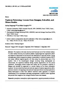
Fig. 3. X-ray diffraction patterns of calcined thin-film silica mesophases. Trace A: Unirradiated film pattern, consistent with a 1-dH mesophase with lattice constant a ⫽ 42.1 Å . Trace B: Irradiated film pattern, consistent with a tetragonal mesophase with a ⫽ 66.8 Å and b ⫽ c ⫽ 72.8 Å, along with parent 1-dH mesophase with a ⫽ 38.5 Å. Trace C: An unirradiated film exposed to HCl vapors and then calcined. The pattern is similar to the one obtained for the irradiated film (trace B) but with lattice constants a ⫽ 74.2 Å and b ⫽ c ⫽ 82 Å for the tetragonal mesophase and a ⫽ 43 Å for the 1-dH mesophase.
Fig. 4. Cross-sectional TEM images of patterned film. (A) [110] orientation of unirradiated calcined region prepared as in Fig. 3, trace A. The striped pattern is consistent with a 1-dH mesophase with a ⫽ 37 Å. (B) Irradiated calcined region prepared as in Fig. 3, trace B, capturing the mesophase transformation from 1-dH to tetragonal. Insets: Magnified images of (A) and (B) showing relationship between the 1-dH (left) and tetragonal mesophases and defining the a and c lattice constants of the transformed tetragonal mesophase (right).
www.sciencemag.org SCIENCE VOL 290 6 OCTOBER 2000
109
REPORTS Fig. 5. Schematic diagram showing the mechanism of the transformation from the 1-dH mesophase (top) to a tetragonal (distorted cubic) mesophase (bottom). As condensation of the siloxane framework proceeds, the framework charge density decreases relative to that of the EO head groups. The corresponding increase in the optimal surfactant headgroup area drives the mesophase transformation from 1-dH to tetragonal through a periodically undulating intermediate, as is known for the thermally driven transformation from 1-dH to body-centered cubic of C12EO12 in the C12EO12/H2O binary system (32). Table 2. Ellipsometry data showing thickness (t) and refractive index (n) (at ⫽ 630 nm) for films exhibiting the phase transformation from 1-dH to tetragonal. As-prepared films
Unirradiated UV-irradiated
t (nm)
n
t (nm)
n
365.1 ⫾ 2.6 360.2 ⫾ 2.1
1.454 ⫾ 0.001 1.457 ⫾ 0.001
229.3 ⫾ 2.2 239.9 ⫾ 2.3
1.302 ⫾ 0.002 1.277 ⫾ 0.002
5 and by TEM in Fig. 4, A and B. There are two previous reports of condensation-driven transformations to higher curvature mesophases: lamellar to 1-dH (31) and lamellar to cubic (11), but our study appears to be the first report of a hexagonal-to-cubic or tetragonal transformation. Because it depends critically on the initial surfactant and acid concentrations (33), the transformation may be realized or avoided (scheme 3 versus scheme 2 of Fig. 1) by judicious choice of these parameters. Although optical patterning of average properties, such as density, of disordered solgel films has been reported previously (23, 24, 34), the uniform initial pore size of our photosensitive thin-film mesophases, combined with the UV-dose dependence of our patterning procedure, provide a unique ability to precisely adjust and spatially define the pore size along with the refractive index and surface area by means of grayscale lithography. The observed hexagonal-to-tetragonal phase transformation further allows patterning of pore connectivity. These features are of practical importance for applications such as membranes and microfluidic systems. References and Notes
1. C. T. Kresge, M. E. Leonowicz, W. J. Roth, J. C. Vartuli, J. S. Beck, Nature 359, 710 (1992). 2. Y. N. Xia and G. M. Whitesides, Annu. Rev. Mat. Sci. 28, 153 (1998). 3. P. D. Yang et al., Science 282, 2244 (1998).
110
Calcined films
4. M. Trau et al., Nature 390, 674 (1997). 5. H. Y. Fan et al., Nature 405, 56 (2000). 6. Precursor solutions were prepared by addition of the surfactant [Brij 56, C16H33(OCH2CH2 )10OH] and the PAG (a diaryliodonium hexafluoroantimonate salt) to polymeric silica sols made by a two-step procedure (A2**), designed to minimize the siloxane condensation rate and foster facile silica-surfactant supramolecular self-assembly during film deposition. First, TEOS [Si(OC2H5)4], ethanol, water, and HCl (mole ratios 1: 4:1: 5 ⫻ 10⫺5) were heated at 60°C for 90 min. This solution was diluted on a volume basis with ethanol (one volume of solution to two volumes of C2H5OH), followed by the addition of water and HCl. Finally, surfactant and the PAG were added so that the final reactant mole ratios were 1 TEOS : 20 C2H5OH : 3.1 H2O : 0.0065 HCl : 0.063 to 0.127 Brij 56 : 0.0156 PAG. 7. C. J. Brinker and G. W. Scherer, Sol-Gel Science (Academic Press, San Diego, CA, 1990), pp. 139 –142. 8. C. J. Brinker et al., Access in Nanoporous Materials, T. J. Pinnavaia and M. F. Thorpe, Eds. (Plenum, New York, 1995), pp. 123–139. 9. Films were deposited on (100) silicon by dip-coating at 25.4 cm/min. Within 30 to 60 min of deposition, the samples were irradiated at 256 nm for times ranging from 15 s to 2 hours through a mask via proximity printing to effectively transfer the pattern onto the silica thin film. Etching of the films was done with a 0.2 M aqueous NaOH solution for a period of 5 to 10 s. Calcination treatments to promote continued siloxane condensation and remove surfactant templates and residual organics associated with PAG were conducted in air at 450°C for 3 hours, using a ramp rate of 1°C/min. HCl exposures of unirradiated films were done by placement in a chamber containing dispersed droplets of concentrated HCl for 2 hours. 10. C. J. Brinker, Y. F. Lu, A. Sellinger, H. Y. Fan, Adv. Mater. 11, 579 (1999). 11. Y. F. Lu et al., Nature 389, 364 (1997).
12. J. V. Crivello and J. H. W. Lam, Macromolecules 10, 1307 (1977). 13. In aqueous solution, ethyl violet is violet-blue for pH ⱖ 2 and yellow for pH ⬍ 0. 14. Magic-angle spinning 29Si nuclear magnetic resonance (NMR) indicates an extent of condensation of 82.1% (Q2/Q3/Q4 ⫽ 8.22/55.08/36.7) for irradiated powdered films (2 hours of UV exposure) as compared to 80.8% (Q2/Q3/Q4 ⫽ 9.61/57.75/ 32.64) for the corresponding unirradiated samples. The superscript “i” in Qi represents the number of bridging oxygens surrounding the central silicon atom. It can be expected that this difference is much greater immediately after irradiation, but lengthy acquisition times (16 hours) needed to perform the NMR experiment preclude our acquisition of data at time (t) ⫽ 0 and allow continued siloxane condensation to occur, diminishing this difference. 15. An etching resolution of 1 m was demonstrated with a C3F8 plasma etching procedure (D. A. Doshi, M. J. Barela, C. J. Schwarz, unpublished results). 16. R. D. Miller, Science 286, 421 (1999). 17. Preliminary work using aqueous solutions of metal salts has demonstrated patterning of Ni and Co oxides into optically defined periodic arrays within thin-film silica mesophases. 18. J. Samuel, C. J. Brinker, L. J. D. Frink, F. van Swol, Langmuir 14, 2602 (1998). 19. M. Lu and C. J. Brinker, Mater.Res. Soc. Symp. Proc. Boston Mass. 594, 463 (1999). 20. See supplementary information at www.sciencemag. org/feature/data/1052932.shl. 21. Films were made using lower ethanol content and methyltriethoxysilane (MTES) to obtain thick crack-free films. The molar ratio used was 1 TEOS : 1 MTES : 3.8 C2H5OH : 7 H2O : 0.01 HCl : 0.096 Brij 56 : 0.014 PAG. 22. K. Simmons-Potter, B. Potter, M. Sinclair, Jpn. J. Appl. Phys. Part 1 Regul. Pap. Short Notes Rev. Pap. 37, 8 (1998). 23. D. Blanc, S. Pelissier, K. Saravanamuttu, S. I. Najafi, M. P. Andrews, Adv. Mater. 11, 1508 (1999). 24. Y. Moreau et al., Opt.Eng. 37, 1130 (1998). 25. V. K. Gupta and N. L. Abbott, Science 276, 1533 (1997). 26. We define the coordinate system to maintain the c direction parallel to the cylinder axes of the asdeposited hexagonal mesophase. The two in-plane directions (b and c) experience a constraint to shrinkage, whereas the a direction normal to the substrate is unconstrained and hence free to shrink, resulting in the smallest lattice constant. For the transformed mesophase, the lattice constant c is determined from TEM (Fig. 4B). Using c to solve the d111 spacing in the XRD pattern (Fig. 3, trace B) we find b ⫽ c. 27. The (200) and (400) reflections of the tetragonal phase can also be indexed as the (100) and (200) reflections of the untransformed parent 1-dH mesophase. 28. The occasional presence of horizontal stripes suggests an incomplete phase transformation from 1-dH to tetragonal, perhaps due to the influence of the substrate. TEM and XRD were used to confirm the phase transformation in bulk samples. 29. J. Israelachvili, Intermolecular and Surface Forces (Academic Press, San Diego, CA, 1992), pp. 341–389. 30. J. N. Israelachvili, D. J. Mitchell, B. W. Ninham, J. Chem. Soc. 2, 1525 (1976). 31. A. Monnier et al., Science 261, 1299 (1993). 32. P. Sakya, J. M. Seddon, R. H. Templer, R. J. Mirkin, G. J. T. Tiddy, Langmuir 13, 3706 (1997). 33. In an initial study of the effects of surfactant and acid concentration on mesophase development, we observed samples prepared with 2 to 3 weight % Brij-56 surfactant and without PAG to exhibit a 1-dH mesophase after deposition and after calcination. Samples prepared with 3 weight % Brij-56 but with a higher acid concentration exhibited a transformation from 1-dH to tetragonal when heated. Similarly, samples prepared with 4 weight % Brij-56 and without PAG exhibited a transformation from 1-dH to tetragonal when heated. Through the introduction of PAG, followed by UV irradiation and heating, we
6 OCTOBER 2000 VOL 290 SCIENCE www.sciencemag.org
REPORTS were able to realize the transformation from 1-dH to tetragonal for the 3 weight % Brij-56 specimen. 34. P. Coudray, J. Chisham, M. P. Andrews, S. I. Najafi, Opt. Eng. 36, 1234 (1997). 35. G. C. Frye, A. J. Ricco, S. J. Martin, C. J. Brinker, Mat. Res. Soc. Symp.Proc. 121, 349 (1988). 36. We thank C. Braunbarth for discussions about the
phase transformation, R. Assink for assistance with NMR experiments, and Y. Guo for assistance with TEM. Partially supported by the University of New Mexico/NSF Center for Micro-Engineered Materials, Fonds zur Foerderung der Wissenschaftlichen Forschung Austria, the U.S. Department of Energy (DOE) Basic Energy Sciences Program, and Sandia
Vibrational Promotion of Electron Transfer Yuhui Huang,1 Charles T. Rettner,2 Daniel J. Auerbach,2 Alec M. Wodtke1 By using laser methods to prepare specific quantum states of gas-phase nitric oxide molecules, we examined the role of vibrational motion in electron transfer to a molecule from a metal surface free from the complicating influence of solvation effects. The signature of the electron transfer process is a highly efficient multiquantum vibrational relaxation event, where the nitrogen oxide loses hundreds of kilojoules per mole of energy on a subpicosecond time scale. These results cannot be explained simply on the basis of Franck-Condon factors. The large-amplitude vibrational motion associated with molecules in high vibrational states strongly modulates the energetic driving force of the electron transfer reaction. These results show the importance of molecular vibration in promoting electron transfer reactions, a class of chemistry important to molecular electronics devices, solar energy conversion, and many biological processes. The prototypical process of electron transfer is one of the most fundamental elementary chemical reactions found in nature. The pioneering work of Marcus (1) has exploded into a vigorous field of chemical and biochemical research, which has been recently reviewed (2). Electron transfer rates are controlled by two central dynamics: “solvent polarization” and “intramolecular vibrational motion.” Under certain circumstances, it is the reorganization of the polarizable solvent about the moving charge that controls the rate of reaction (1). Under other circumstances, the electron transfer rate can only be understood by including effects of intramolecular vibration either classically (3) or quantum mechanically (4 – 6). Although hybrid models that incorporate both effects have recently been developed (7–11), our understanding of the dynamics of this important process is still far from complete. Furthermore, although studies of solvent influences on electron transfer have been quite successful (12, 13), the difficulties of performing state-resolved experiments in condensed phases have limited experiments on vibrational influences (14). We found a way to at once remove the complicating effects of the solvent and to control the vibrational state of the reacting molecule by studying electron transfer dynamics between an incident gas molecule and a metal surface. This model system is in many ways
dynamically equivalent to condensed phase electron transfer, but solvent effects appear in a much simpler way. Specifically, the interaction of the ion with the solvent is replaced by an interaction with its image charge in the metal, which is much more easily modeled (15, 16). Furthermore, this approach allows the application of gas-phase optical pumping to prepare single quantum states in very high vibrational states in order to amplify the possible effects of vibration on electron transfer. We show that high levels of vibrational excitation can promote electron transfer from a metal surface to a gas-phase molecule. This work builds on previous condensed phase studies that have revealed substantial enhancements of electron transfer rates with vibrational excitation (14)
National Laboratory’s Laboratory Directed R&D program. This work was done under contract from DOE. Sandia is a multiprogram laboratory operated by Sandia Corporation, a Lockheed Martin Company, for DOE under contract DE-AC04-94AL85000. 7 June 2000; accepted 16 August 2000
and provides a model system for the development of sophisticated charge transfer theories. Electron transfer rates depend on molecular vibration because the shape of the molecule changes upon charge transfer. Classically, trajectories of vibrationally excited states can more easily traverse regions of configuration space similar to the stable anion. For the case of NO, we quantitatively calculated the form of the relevant molecular potentials (17) (Fig. 1A). The difference between the two potential functions (Fig. 1B) is the vertical electron binding energy versus N–O separation. Near their potential minima, there is little energy difference between the neutral and anion curves, consistent with the low electron affinity associated with NO. For vibrationally excited states, however, near the outer turning point of the vibration state v ⫽ 15 (bond length RNO ⬃ 1.6 Å), the vertical attachment energy to form NO⫺ is ⬎200 kJ/mol. At the inner turning point, electron attachment is endoergic by about the same amount. This simple analysis shows that the energetic constraints controlling the ability of NO to accept (or, concomitantly, the ability of NO⫺ to donate) electrons depend strongly on internuclear separation. Previously, Newns derived potential parameters for neutral and anionic curves that describe the interaction of NO with Ag(111) (16). These are shown in Fig. 2, adapted to the case of Au(111). The anionic curve is calculated by using a Coulombic interaction between the anion and the image charge of the metal. The neutral curve reflects the weak physical interactions of NO with the noble metals. The asymptotic separation between the neutral and Fig. 1. (A) Ab initio calculations of NO and NO⫺, showing the energetic constraints on electron transfers. (B) The difference between the two potential curves. The positions of the inner and outer extrema of the NO (v ⫽ 15) vibrational wave function are shown with vertical arrows labeled (r⬍ and r⬎). The position of the NO potential minimum is shown as re.
1 Department of Chemistry, University of California, Santa Barbara, CA 93106, USA. 2IBM Research Division, Almaden Research Center, San Jose, CA 95120 – 6099, USA.
www.sciencemag.org SCIENCE VOL 290 6 OCTOBER 2000
111