path energy routing; muli-hop energy transfer; energy efficiency. I. INTRODUCTION. Substantial benefits can be reaped with the use of Wireless.
2014 IEEE 25th International Symposium on Personal, Indoor and Mobile Radio Communications
Implementation of Multi-Path Energy Routing Deepak Mishra,∗ K Kaushik,∗ Swades De,∗ Stefano Basagni,† Kaushik Chowdhury,† Soumya Jana,‡ and Wendi Heinzelman § ∗
Department of Electrical Engineering, IIT Delhi, New Delhi, India of Electrical and Computer Engineering, Northeastern University, Boston, MA, USA ‡ Department of Electrical Engineering, IIT Hyderabad, Hyderabad, India § Department of Electrical and Computer Engineering, University of Rochester, Rochester, NY, USA † Department
Abstract—Harvesting energy from radio frequency (RF) waves brings us closer to achieving the goal for perpetual operation of a wireless sensor network (WSN) by replenishing the batteries of the sensor nodes. However, due to restrictions on the maximum transmitted power, path loss, and receiver sensitivity, only a small amount of energy can be harvested. While a dedicated RF source alleviates the problem to some extent, novel techniques are required to boost the energy transfer efficiency of the source. In this paper, we provide the first experimental demonstration of multi-path energy routing (MPER) for the case of a sparsely distributed WSNs and show its improved performance over direct energy transfer (DET). In addition, we extend this concept to the case of densely distributed WSNs and experimentally demonstrate and compare the gains obtained by 2- and 3-path energy routing over DET. Our experimental results show that significant energy gains can be achieved in a dense network deployment even when the node to be charged is partially blocked by the neighboring nodes. Index Terms—RF energy transfer; energy harvesting; multipath energy routing; muli-hop energy transfer; energy efficiency
I. I NTRODUCTION Substantial benefits can be reaped with the use of Wireless Sensor Networks (WSNs) in applications such as monitoring of air pollution [1], industrial hazards [2], water quality [3], etc. However, a sensor node is energy constrained due to its limited battery. Recharging the battery of a sensor node by harvesting energy [4] facilitates its uninterrupted operation [5]. Despite the high energy density, solar energy might not be the ultimate choice for harvesting due to its wide spatial and temporal variations. Although ambient energy [6], [7] can be harvested when available, harvesting energy from a dedicated energy source offers reliability [8]. This energy transfer can be radiative or non-radiative, but we will focus on the former (radio frequency (RF) energy transfer), as it does not have the strict constraints of alignment or resonant coupling. Moreover, it has the advantages of beam steering, simultaneous charging of multiple nodes, and combining data and energy transfer over the same RF signal. In a conventional RF energy transfer (RFET) approach (e.g., [9]), a dedicated RF energy source is used to directly charge sensor nodes wirelessly. An RF-DC conversion circuitry at the sensor node acts as a transducer by converting the received RF energy into DC. A super-capacitor is used as an energy storage element to support consumption by the sensor node when needed. In doing so, a significant part of the transmitted
978-1-4799-4912-0/14/$31.00 ©2014 IEEE
energy is lost due to path loss, transducer inefficiency, and low receiver sensitivity. In addition, the upper bound on maximum permissible power limits the received power at a sensor node. Communication and network-level approaches to improve the RF energy harvesting efficiency led to the concept of MultiHop Energy Transfer (MHET) [8]. In this paper, we have considered two network deployments, sparse and dense. RF energy transfer in a sparse deployment is likely to experience no hindrance caused by neighboring sensor nodes due to large inter nodal distances of the field nodes and also due to the small distance of the RF source to the target node because of low energy sensitivity of the receiver. In order to improve the harvesting efficiency, we introduce dummy nodes that act as RF energy routers. In our experimental demonstration, we emulate a sparse network deployment by placing the dummy nodes at positions where they do not obstruct the energy transmission from the RF source to the sensor node. In a dense deployment, due to the high density of nodes, charging of one sensor node directly using line of sight (LOS) RF energy transmission may not be very efficient because of blocking/shadowing caused by neighboring sensor nodes. While demonstrating multi-path energy routing (MPER) in this scenario, we emulate a dense deployment of neighboring sensor nodes that cause marginal blocking of the LOS energy transmission from the source. MPER is implemented in this case by making the neighboring sensor nodes act as energy routers for energy transmission from the RF source. In this paper, we term the dummy nodes in the sparse scenario and also the neighboring sensor nodes in the dense scenario as intermediate nodes. The sensor node targeted to be charged by the RF source for charging is termed as end node. We introduce a novel technique, called multi-path energy routing (MPER), and show the energy gains that can be obtained by demonstrating 2-path and 3-path energy routing, and comparing the gains with respect to traditional (direct or 1-hop) RF energy transfer (called DET). We implement the MPER in sparse as well as dense deployment scenarios. To the best of our knowledge, this paper provides the first implementation of a network employing MPER. The key contributions can be summarized as follows:
1834
•
In a sparse network deployment scenario, we demonstrate 2-path energy routing and show the gain of MPER over
DET. In addition, we demonstrate 3-path energy transfer for the sparse scenario by having two 2-hop paths symmetrically placed on the either side of the direct path and show its gain over DET. • We further implement MPER in a dense deployment scenario and demonstrate 3-path energy routing that involves implementation of 3-hop RFET. The improvements of 3path energy routing over 2-path energy routing as well as that with respect to DET are empirically measured. The rest of the paper is organized as follows. In Section II, we present the related work. Section III presents the experimental demonstration and a discussion of MPER in a sparse network scenario. MPER in the case of a dense network scenario and 3-path energy routing is demonstrated, and comments on the results are presented, in Section IV. Section V concludes the paper. •
II. R ELATED RESEARCH Power cord elimination is possible partially or completely these days due to advances in the field of wireless power transfer and RF energy harvesting. Battery elimination is also now a reality, by which significant savings can be achieved in densely populated wireless sensor networks. As a result, the form factor and lifetime of the devices can be improved. The benefits of RF wireless energy transfer also include non-LOS, contact-less energy transfer. A Wireless Identification and Sensing Platform (WISP) was presented by the authors in [10] where an RFID based platform harvests the wireless energy from the transmitter and then transmits the sensed data using back-scattering. This differs from a typical WSN, as the sensor nodes generate the carrier themselves and then modulate their data onto it. The energy consumption is therefore higher, and when frequent transmissions are required, harvested energy from ambient RF sources is not sufficient and thus a dedicated energy source is required. Commercial RF-ICs such as Si4010 have the advantages of being small in size as well as consuming low power with the integration of the microcontroller (MCU8051) and transceiver onto a single chip. Further research in the micro-electronics have led to the world’s smallest wireless sensor nodes with ultra low power consumption [11]. These fuel the possibility of having continuous operation of a WSN and operating them using a dedicated RF energy source, even with its low energy efficiency. Similar to WISP, advances in energy harvesting have led to other designs, such as Wireless Ambient Radio Power (WARP) [12] and Ambient backscatter Communication (ABC) [13], which have better sensitivity. These devices can harvest useful RF energy even from a distance of around 200 meters using the power from a base transceiver station (BTS). Optimized design of an energy harvesting circuit was proposed in [14]. The circuit can harvest energy as low as −20 dBm, and it has a better harvesting efficiency even compared to the commercial harvesting RFICs from Powercast Inc. [9] in the range of −20 dBm to +7 dBm. In this paper, we use the
commercial RF harvesters from Powercast P1110 [15] due to their availability and ease of use. Due to this lower receiver sensitivity, the distance between the RF source and the energy harvesting receiver is small. There have been very few papers illustrating the novel methods of improving RF source energy efficiency. In [5], a feasibility study of RF multi-hop energy transfer and single hop data transfer was conducted. The authors demonstrated that under certain optimum distance conditions, multi-hop energy transfer is efficient in terms of both energy and time. In [8], via experiments, we demonstrated the two-hop energy transfer and showed the energy gain compared to the DET. However, in that study a dense deployment was considered, where the intermediate node caused marginal shadowing to the DET. Perpetual Wireless Networks (PWNs) fueled by multihop wireless distribution of injected power was discussed in [16]. The authors formulated multi-hop power flow problems and provided numerical results for them. However, they used a non-radiative form of energy transfer based on resonant magnetic induction, rather than radiative form (RFET). In this work, we demonstrate MPER in sparse as well as dense node deployments in WSNs. By implementing MPER in a sparse network, we extend our previous work in [8], by showing that two hop RFET can provide appreciable gains even when the intermediate nodes do not cause shadowing to the LOS path. We show that in the case of sparse network deployments, the energy transfer gain can be improved by placing dummy intermediate nodes around the LOS path to the end node. With the dense node deployment, we show that we can achieve significant energy gain using MPER even when DET to the end node is slightly blocked by the neighboring nodes. It is important to note that the studies on both the sparse as well as dense network deployments are of interest. The first case demonstrates that the intermediate nodes can aid in RFET even without influencing the DET path. The second case, on the other hand, is of interest because, even though the intermediate nodes may cause some blocking to the DET, the overall gain in energy transfer in this case with respect to the DET (without the presence of the intermediate nodes) can be even higher than the gain in the first case. III. MPER IN SPARSE NETWORKS MPER is a technique in which we increase the efficiency of traditional RF energy transfer (DET) by introducing energy routers. These energy routers harvest the energy from the RF source and transmit it to the nearby sensor node being charged by the RF source. In this section, we will observe that RFET from the source to the end node can be improved by placing a dummy node at such a position between them such that it acts as an energy router without causing any blocking of the DET from the source to the end node. In this way, this two-hop set-up provides some gain over the existing single-hop with no intermediate node by implementing 2-path energy routing, i.e., direct path and 2-hop path. We further improve the RFET efficiency by placing the intermediate node on the other side of the LOS path between the RF source and the end node, in
1835
TABLE I: System specifications for MPER with two 2-hop paths along with a direct path
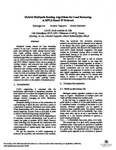
(a) 3-path, 2-hop RF energy transfer
(b) Experimental set-up
Fig. 1: MPER in a sparse network
order to get two 2-hop paths along with the direct path, thus implementing 3-path energy routing as shown in Fig. 1(a). In this way, we can improve the gains significantly. A. Experimental set-up for MPER in a sparse network The system specifications for the experimental set-up of 3path energy routing are provided in Table I. The RF source, nodes positions, and inter-node distances are as shown in Fig. 1(b). The intermediate nodes act like energy routers, as they transfer the energy stored in the 50mF capacitor that itself was harvested from the RF source. The intermediate nodes transmit energy in the form of data packets sent via the +6 dBi antenna by the Mica2 mote. This transmission is discontinuous as compared to the continuous transfer of energy from the RF source due to the continuous charging (OFF or no transmission state) and discharging (ON or transmission state) of the super-capacitor. It should be noted that the energy router can harvest and also transmit energy at the same time as it has two antennae; one for harvesting energy and the other for transmission. For efficient RFET, the Mica2 mote has been programmed to transmit packets continuously one after the other during the ON state. For more details related to mote programming, the reader may refer to our previous work [8]. Moreover, here we are using 1 dBi omnidirectional antenna at the end node so that it can receive power efficiently from all directions, which is required in this case because the distance between the end node and the intermediate node has been kept larger to avoid any blocking. It should be noted that the intermediate nodes (left and right) are not part of the set-up for the DET case. B. Experimental results We considered two variations of 2-path energy routing, namely, left-direct and right-direct scenarios. In the left-direct scenario, out of 2 intermediate nodes in Fig. 1(b), only the left intermediate node is present, whereas in the right-direct scenario, only the right intermediate node is present in the setup. The 3-path energy routing can be identified as left-rightdirect scenario, where the left and right paths are 2-hop and
S. No.
Node Type
1
RF Source
2
Intermediate nodes (1, 2)
3
End node
Components HAMEG RF Synthesizer transmitting +13 dBm at 915 MHz Powercast +6 dBi PCB patch antenna Powercast P1110 EVB Mica2 mote Two Powercast +6 dBi PCB patch antennas Powercast P1110 EVB Powercast +1 dBi PCB dipole antenna
the direct path is 1-hop. The performances in these cases of two paths along with that of three paths have been compared with the DET. 1) Voltage gain: Voltage gain at the end node is the ratio of the difference in the voltage levels up to which the end node’s super-capacitor is charged in a fixed time interval for the 2-path or 3-path case as compared to the case of DET. For finding voltage gains, the experiment has been performed for three time intervals: 10 min, 15 min, and 20 min, and the results are tabulated in Table II. The results show that both the left-direct scenario and the right-direct scenario provide voltage gains over DET. Moreover, the gains of 3-path energy routing are almost twice that of the left-direct scenario or the right-direct scenario, signifying that 3-path energy routing can provide significant improvements over 2-path energy routing. 2) Time gain and energy savings: Time gain at the end node is the ratio of the difference of the time that it takes to charge the end node’s super-capacitor to a fixed voltage level in the 2-path or 3-path case as compared to the time taken in the DET case. The experiment has been performed for three voltage levels: 1 V, 2 V, and 3 V, and the results are tabulated in Table III. The results show that both the left-direct and right-direct scenarios provide time gains over DET. Moreover, the gains from 3-path energy routing are much higher than that of 2-path energy routing. As the power consumed at the RF source is 41.27 W, which is transmitting at +13 dBm, the energy savings in MPER can be calculated by multiplying the time saved due to shorter running time required for the RF source with the power consumption of the RF source, i.e., 41.27 W. However, the energy gain is the same as the time gain, as both Time and Energy are proportional for a constant power. IV. MPER IN DENSE NETWORKS In this section, we illustrate how the efficiency of energy transfer from the RF source to the end node can be increased with the help of two intermediate nodes directly between the RF source and the end node. It is to be noted that the intermediate nodes are part of the network (sensor nodes) and have an advantage of harvesting more energy in the same amount of time compared to that of the end node due to their shorter distance from the RF source. Hence, they can act as energy routers by transmitting the harvested energy from the RF source. Now, we explain how MPER can take place in a dense
1836
TABLE II: Voltage gains for 2-path and 3-path energy routing in a sparse network Exp. No.
VDET (V)
1 2 3
2.02 2.00 2.02
Exp. No.
VDET (V)
1 2 3
2.50 2.48 2.48
Exp. No.
VDET (V)
1 2 3
2.78 2.76 2.74
Vlef t−direct (V) 2.12 2.16 2.10
left-direct gain (%) 4.95 8.00 3.96
Vlef t−direct (V) 2.64 2.66 2.62
left-direct gain (%) 5.60 7.25 5.65
Vlef t−direct (V) 2.94 2.94 2.92
left-direct gain (%) 5.76 6.52 6.57
Time interval Vright−direct (V) 2.12 2.12 2.10 Time interval Vright−direct (V) 2.64 2.62 2.58 Time interval Vright−direct (V) 2.92 2.92 2.88
= 10 min right-direct gain (%) 4.95 6.00 3.96 = 15 min right-direct gain (%) 5.60 5.65 4.03 = 20 min right-direct gain (%) 5.04 5.80 5.11
Average 2-path gain
V3−path (V)
5.31 %
2.22 2.24 2.22
Average 2-path gain
V3−path (V)
5.63 %
2.74 2.76 2.72
Average 2-path gain
V3−path (V)
5.80 %
3.04 3.06 3.02
3-path gain (%) 9.90 12.00 9.90
Average 3-path gain
3-path gain (%) 9.60 11.29 9.68
Average 3-path gain
3-path gain (%) 9.35 10.87 10.22
Average 3-path gain
3-path gain (%) 11.30 11.97 9.57
Average 3-path gain
3-path gain (%) 15.25 15.00 14.24
Average 3-path gain
3-path gain (%) 28.75 29.76 28.02
Average 3-path gain
10.6 %
10.19 %
10.15 %
TABLE III: Time gains for 2-path and 3-path energy routing in a sparse network Exp. No.
TDET (sec)
1 2 3
230 234 230
Exp. No.
TDET (sec)
1 2 3
590 600 590
Exp. No.
TDET (sec)
1 2 3
1600 1566 1620
Tlef t−direct (sec) 220 216 222
left-direct gain (%) 4.35 7.69 3.48
Tlef t−direct (sec) 548 530 554
left-direct gain (%) 7.12 11.67 6.10
Tlef t−direct (sec) 1280 1260 1302
left-direct gain (%) 20.00 19.54 19.63
Voltage level = 1 V Tright−direct right-direct (sec) gain (%) 218 5.22 222 5.13 224 2.61 Voltage level = 2 V Tright−direct right-direct gain (%) (sec) 538 8.81 540 10.00 560 5.08 Voltage level = 3 V Tright−direct right-direct gain (%) (sec) 1288 19.50 1290 17.62 1340 17.28
network with the help of a block diagram as shown in Fig. 2. In the case of direct (1-hop) energy transfer, as shown in Fig. 2a, the two intermediate nodes that are in between the RF source and the end node have no transmission capability. As a result, the end node only receives via direct path (1-hop) from the RF source. On the other hand, in 2-path energy routing (Fig. 2b), only the intermediate node 2 has the transmission capability. In this case, the end node receives energy from the RF source directly (via one hop) as well as via two hops – through intermediate node 2, which acts as an energy router. In the case of three paths (Fig. 2c), both intermediate nodes 1 and 2 have the transmission capability. As a result, the end node receives via one hop from the RF source, via two hops from the RF source with intermediate node 2 acting as an energy router, and via three hops from the RF source with intermediate node 1 as the first energy router and intermediate node 2 acting as a second energy router. As the intermediate nodes transmit discontinuously at +3 dBm, there is no energy received at the end node directly from the first intermediate node as the transmission is also blocked by the second intermediate node. The main difference here from the MPER in the case of the sparse network set-up as discussed in Section III is that in a sparse network deployment, intermediate nodes were not part of the network, i.e., they are not the sensor nodes; rather,
Average 2-path gain
T3−path (sec)
4.75 %
204 206 208
Average 2-path gain
T3−path (sec)
8.13 %
500 510 506
Average 2-path gain
T3−path (sec)
18.93 %
1140 1100 1166
10.95 %
14.83 %
28.84 %
Fig. 2a: Direct (1-hop) energy transfer (DET)
Fig. 2b: Two path (1-hop and 2-hop) energy routing
Fig. 2c: Three path (1-hop, 2-hop, and 3-hop) energy routing
they are dummy nodes that are used as energy routers for improving the energy transfer efficiency. Whereas in this case, the intermediate nodes are part of the network and are like the
1837
end node and other sensor nodes with additional transmission capability for improving the RFET efficiency by acting as energy routers. In addition, here a +6 dBi directional antenna has been used to overcome the blocking loss, and also as the intermediate nodes are very close to the end node as compared to the RF source, the end node antenna need not be omnidirectional. TABLE IV: System specifications for MPER in a dense network S. No.
Node Type
1
RF Source
2
Intermediate nodes (1, 2)
3
End node
it can help in getting more ON-OFF cycles (discharging and charging of the super-capacitor) at the second intermediate node in the 3-hop case than in the 2-hop case when the first intermediate node was OFF. Fig. 4 shows a snapshot of the digital oscilloscope reading that shows the voltage plots for the intermediate nodes 1, 2, and the end node on channels 1, 2, and 3, respectively. It is clearly visible in the snapshot that the number of ON-OFF cycles for the first intermediate node are much higher than the second.
Components Hittite RF Synthesizer transmitting +23 dBm at 915 MHz Powercast +6 dBi PCB patch antenna Powercast P1110 EVB Mica2 mote Two Powercast +6 dBi PCB patch antennas Powercast P1110 EVB Powercast +6 dBi PCB patch antenna
Fig. 4: Snapshot of the oscilloscope reading for 3-path energy routing in a dense deployment
B. Experimental results
Fig. 3: Experimental set-up for MPER in a dense network
A. Experimental set-up for MPER in a dense network The system specifications for experimental demonstration of MPER in a dense networks are provided in Table IV. In the experimental set-up as shown in Fig. 3, the RF source and the nodes have been placed in positions that support 3-hop energy transfer, i.e., the first intermediate node is in a better position than the second intermediate node, which itself is in a better position than the end node. Thus, the second intermediate node receives energy from the RF source in a two hop fashion via the first intermediate node and then it itself acts as a 3-hop energy router along with the first intermediate node to the end node. The inter node distances and the node positions are as shown in Fig. 3. It may be noted here that this set-up can be considered to be a special case of the sparse network where the RFET to end node is shadowed by the presence of the nearby intermediate nodes, which are closer to the end node (better position than the end node). Here we have intentionally tried to create a scenario that best suits the 3-hop energy transfer, i.e., the first node has been kept at the best position so that
For finding voltage gains, the experiment has been performed for three time intervals: 5 min, 10 min, 15 min, and the results are tabulated in Table V. The results show that both 2-path (1-hop and 2-hop) and 3-path (1-hop, 2-hop, and 3-hop) MPER provide voltage gains over single path energy transfer. The voltage gains from 3-path are almost twice as that of 2path, signifying that in some cases like the existing set-up, 3-hop can provide significant improvements over 2-hop. Similarly, for finding time gains, the experiment has been performed for three voltage levels: 1 V, 2 V, 3 V and the results are tabulated in Table VI. Here again, the results show that both 2-path and 3-path RFET provide time gains over single path. Moreover, the time gains from 3-path are better than that of 2-path energy routing. As the power is consumed at the RF source, which is transmitting at +23 dBm, the time gains representing the time saved provides energy savings as we need to transmit power for a shorter duration in the case of 3-path (or 2-path) as compared to single path. V. C ONCLUSIONS AND FUTURE WORK In this work, we have illustrated the potential gains that can be obtained by charging a node from an RF source through MPER. In particular, we have considered sparse as well as dense network deployment cases. For the case of sparsely deployed networks, MPER can provide significant gains over a direct path without the intermediate node causing any blocking to the target node. In dense deployments, we observed that energy transfer gains are obtained by using neighboring nodes
1838
TABLE V: Voltage gains for 2-path and 3-path energy routing in a dense network Exp. No. 1 2 3
V1path (1-hop)(V) 0.90 0.86 0.88
V2path (1 and 2 hop)(V) 0.96 0.94 0.96
Exp. No. 1 2 3
V1path (1-hop)(V) 1.64 1.58 1.60
V2path (1 and 2 hop)(V) 1.74 1.68 1.70
Exp. No. 1 2 3
V1path (1-hop)(V) 2.22 2.14 2.16
V2path (1 and 2 hop)(V) 2.38 2.30 2.32
Time interval = 5 min 2-path Gain (%) Avg. 2-path Gain 6.7 9.3 8.4 % 9.1 Time interval = 10 min 2-path Gain (%) Avg. 2-path Gain 6.1 6.3 6.2 % 6.2 Time interval = 15 min 2-path Gain (%) Avg. 2-path Gain 7.2 7.5 7.4 % 7.4
V3path (1,2 and 3 hop)(V) 1.00 0.98 1.00
3-path Gain (%) 11.1 14.0 13.6
Avg. 3-path Gain
V3path (1,2 and 3 hop)(V) 1.84 1.78 1.80
3-path Gain (%) 12.2 12.7 12.5
Avg. 3-path Gain
V3path (1,2 and 3 hop)(V) 2.50 2.42 2.44
3-path Gain (%) 12.6 13.1 13.0
Avg. 3-path Gain
12.9 %
12.5 %
12.9 %
TABLE VI: Time gains for 2-path and 3-path energy routing in a dense network Exp. No. 1 2 3
T1path (1-hop)(sec) 334 350 344
T2path (1 and 2 hop)(sec) 314 326 322
Exp. No. 1 2 3
T1path (1-hop)(sec) 768 800 788
T2path (1 and 2 hop)(sec) 712 744 738
Exp. No. 1 2 3
T1path (1-hop)(sec) 1474 1494 1490
T2path (1 and 2 hop)(sec) 1278 1330 1310
Voltage level = 1 V 2-path Gain (%) Avg. 2-path Gain 6.0 6.9 6.4 % 6.4 Voltage level = 2 V 2-path Gain (%) Avg. 2-path Gain 7.3 7.0 6.9 % 6.3 Voltage level = 3 V 2-path Gain (%) Avg. 2-path Gain 13.3 11.0 12.1 % 12.1
as energy routers despite the shadowing on the target node caused by neighboring nodes. These gains can be useful in extending the network lifetime by saving the time of charging the sensor nodes. Our results also provide insight into the ability to use a single RF source to charge multiple nodes at the same time. Currently, due to hardware limitations, the inter node distances are low. As future work, we intend to optimize the node-level components and thereby further improve the range of RF energy transfer. R EFERENCES [1] F. Tsow, E. Forzani, A. Rai, R. Wang, R. Tsui, S. Mastroianni, C. Knobbe, A. Gandolfi, and N. Tao, “A wearable and wireless sensor system for real-time monitoring of toxic environmental volatile organic compounds,” IEEE Sensors J., vol. 9, no. 12, pp. 1734–1740, Dec. 2009. [2] V. Gungor and G. Hancke, “Industrial wireless sensor networks: Challenges, design principles, and technical approaches,” IEEE Trans. Industrial Electronics, vol. 56, no. 10, pp. 4258–4265, Oct. 2009. [3] B. O’Flyrm, R. Martinez, J. Cleary, C. Slater, F. Regan, D. Diamond, and H. Murphy, “Smartcoast: A wireless sensor network for water quality monitoring,” in Proc. IEEE Conf. Local Computer Networks, Dublin, Ireland, Oct. 2007, pp. 815–816. [4] S. Basagni, M. Y. Naderi, C. Petrioli, and D. Spenza, “Wireless sensor networks with energy harvesting,” in Mobile Ad Hoc Networking: Cutting Edge Directions, S. Basagni, M. Conti, S. Giordano, and I. Stojmenovic, Eds. Hoboken, NJ: John Wiley & Sons, Inc., Mar. 5 2013, ch. 20, pp. 703–736. [5] S. De and R. Singhal, “Toward uninterrupted operation of wireless sensor networks,” IEEE Computer Mag., vol. 45, no. 9, pp. 24–30, Sep. 2012. [6] H. Nishimoto, Y. Kawahara, and T. Asami, “Prototype implementation of ambient RF energy harvesting wireless sensor networks,” in IEEE Sensors J., Waikoloa, USA, Nov. 2010, pp. 1282–1287.
T3path (1,2 and 3 hop)(sec) 296 304 302
3-path Gain (%) 11.4 13.1 12.2
Avg. 3-path Gain
T3path (1,2 and 3 hop)(sec) 660 692 686
3-path Gain (%) 14.1 13.5 12.9
Avg. 3-path Gain
T3path (1,2 and 3 hop)(sec) 1198 1254 1230
3-path Gain (%) 18.7 16.1 17.5
Avg. 3-path Gain
12.2 %
13.5 %
17.4 %
[7] V. Raghunathan, A. Kansal, J. Hsu, J. Friedman, and M. Srivastava, “Design considerations for solar energy harvesting wireless embedded systems,” in Fourth Intl. Symp. Information Processing in Sensor Networks ( IPSN), Los Angeles , USA, Apr. 2005, pp. 457–462. [8] K. Kaushik, D. Mishra, S. De, S. Basagni, W. Heinzelman, K. Chowdhury, and S. Jana, “Experimental demonstration of multi-hop RF energy transfer,” in IEEE 24th Int. Symp. on Personal Indoor and Mobile Radio Communications (PIMRC), London, UK, Sep. 2013, pp. 538–542. [9] Powercast, http://www.powercastco.com, 2013. [10] A. Sample, D. Yeager, P. Powledge, A. Mamishev, and J. Smith, “Design of an RFID-based battery-free programmable sensing platform,” IEEE Trans. Instrumentation and Measurement, vol. 57, no. 11, pp. 2608– 2615, Nov. 2008. [11] J. Lu, H. Okada, T. Itoh, T. Harada, and R. Maeda, “Toward the world smallest wireless sensor nodes with ultralow power consumption,” IEEE Sensors J., vol. 14, no. 6, pp. 2035–2041, June 2014. [12] A. Parks, A. Sample, Y. Zhao, and J. Smith, “A wireless sensing platform utilizing ambient RF energy,” in Proc. IEEE Topical Conf. on Wireless Sensors and Sensor Networks (WiSNet), Austin, USA, Jan. 2013, pp. 127–129. [13] V. Liu, A. Parks, V. Talla, S. Gollakota, D. Wetherall, and J. R. Smith, “Ambient backscatter: Wireless communication out of thin air,” in Proc. ACM SIGCOMM, Hong Kong, China, 2013, pp. 39–50. [14] P. Nintanavongsa, U. Muncuk, D. Lewis, and K. Chowdhury, “Design optimization and implementation for rf energy harvesting circuits,” IEEE J. Emerging and Selected Topics in Circuits and Systems,, vol. 2, no. 1, pp. 24–33, Mar. 2012. [15] “Powercast P1110 powerharvester datasheet,” 2013. [Online]. Available: http://www.powercastco.com/PDF/P1110-datasheet.pdf [16] L. Xiang, J. Luo, K. Han, and G. Shi, “Fueling wireless networks perpetually: A case of multi-hop wireless power distribution,” in IEEE 24th Int. Symp. on Personal Indoor and Mobile Radio Communications (PIMRC), London, UK, Sep. 2013, pp. 1994–1999.
1839