Ami Munshi, Srija Unnikrishnan / International Journal of Engineering Research and ..... [9] Soumyasree Bera, Debasish Bhaskar, Rabindranath Bera.
Ami Munshi , Srija Unnikrishnan / International Journal of Engineering Research and Applications (IJERA) ISSN: 2248-9622 www.ijera.com Vol. 2, Issue 3, May-Jun 2012, pp.126-132
Implementation of Radar Transmitter-Receiver using DSBPSK Modulation Technique Ami Munshi#1 , Srija Unnikrishnan*2 #
Watumull Instiute of Electronics Engg and Computer Technology Mumbai University, India * Fr Conceicao Rodrigues College of Engg Mumbai Universiyt, India
Abstract— In this paper, we have implemented Radar Transmitter-Receiver. Direct Sequence Spread Spectrum BPSK is chosen as modulation method because of its numerous advantages like accuracy of ranging, sensitivity, targetseparation, accuracy of power-estimation, interference suppression, etc. We have employed this scheme using MATLAB Simulink which is a software package for modelling, simulating, and analysing dynamic systems at any point. Keywords— Direct Sequence Spread Spectrum, Radar, MATLAB, Simulink, BPSK.
I. INTRODUCTION Radar (RAdio Detection And Ranging) systems are widely used now-a-days in variety of applications including air traffic control, astronomy, air defence systems, ocean surveillance, ground penetrating radars for geological observations, flight control systems, automotive radar for Intelligent Transport System (ITS). Spread spectrum techniques have some fine properties which make them an excellent candidate for Radar applications. The first major application of Spread Spectrum Techniques arose during the mid-sixties, when NASA employed the method to precisely measure the range to deep space probes. In the following years, the US military became enamoured of SST due to its ability to withstand jamming (i.e. intentional interference), and it ability to resist eavesdropping. Today this technology forms the basis for the ubiquitous NavStar Global Positioning System (GPS), the soon to become ubiquitous JTIDS (Joint Tactical Information Distribution System/Link-16) data link (used between aircraft, ships and land vehicles), and last but not least, the virtually undetectable bombing and navigation radar on the bat-winged B-2 bomber [1]. Section2 provides a brief description on mathematical background of Direct Sequence Spread Spectrum Modulation scheme using BPSK. Section 3 gives block diagram of Radar Transmitter-Receiver scheme. The procedure to implement Radar transmitter-receiver using Simulink are explained in this section. Section 4 provides simulation results at each and every step of Radar transmitter-receiver, which are supporting the theory provided in the earlier sections. Finally the work is concluded in section 5 and the scope for future work is explained.
II. DIRECT SEQUENCE SPREAD SPECTRUM MODULATION
A. Definition of Spread Spectrum Modulation It is transmission technique in which pseudo noise code, independent of the data is employed as modulating signal to spread the signal energy over a bandwidth much greater than information signal bandwidth. At the receiver, signal is dispread using replica of pseudo noise code generator [2]. B. Benefits of using Spread Spectrum Modulation Spread-spectrum (SS) transmissions of digital communication signals are widely used in wireless and military applications because they are very effective at suppressing interference. This interference can occur from several sources. One source could be an adversary deliberately jamming the communications channel. Another source is the result of multiple access techniques in which many users simultaneously share the same transmission bandwidth thereby interfering with each other. Lastly, the interference may be the result of channel-induced ISI due to multipath arrivals in a band-limited channel. Spread-spectrum techniques can also be used to hide a signal by transmitting it at low power. By spreading the signal energy over the widest available bandwidth and using the minimum power needed, the signal can be hidden in the channel noise. This means that any unauthorized interceptor will have a low probability of detecting the signal relative to the intended receiver. Likewise because of the pseudo-random properties of the spreading sequence, even if the signal is detected a lower probability of it being intercepted exists. As a result, spread-spectrum signals are called low probability of detection (LPD) and low probability of intercept (LPI) signals must not be used [3]. Some primary motivations for implementing spread-spectrum in radar are accuracy of ranging, sensitivity, target-separation (mu1ti-vehicle detection), accuracy of power-estimation, interference suppression [4][5]. To be considered a spreadspectrum technique, a transmission must have two characteristics: First, the transmission bandwidth of the signal must be much larger than the minimum bandwidth associated with the information data rate W. The second requirement is that the signal’s bandwidth must be spread by using a spreading signal or code that is independent of the data. This code has pseudo-random properties, which allows the receiver
126 | P a g e
Ami Munshi , Srija Unnikrishnan / International Journal of Engineering Research and Applications (IJERA) ISSN: 2248-9622 www.ijera.com Vol. 2, Issue 3, May-Jun 2012, pp.126-132 to know a priori what the code is. Demodulation is then accomplished by correlating the received code with a synchronized replica in the receiver and thereby dispreading the signal. There are two basic methods for implementing spread-spectrum: DSSS involves spreading using phase modulation, FHSS involves rapidly changing the carrier frequency. A basic block diagram of a spread-spectrum system is seen in Figure 1. DSSS is employed in the given system to achieve low error rate and high ranging accuracy [6].
Figure 2: The relationship between the spreading sequence c(t) and the information sequence d(t) for a DSSS signal with six chips per bit.
The chip duration is chosen in order to spread the signal over the maximum available bandwidth of the channel. A rectangular pulse of length T has a null-to-null bandwidth Bnn = 2/T. Therefore for a channel bandwidth W, Tc = 2/W or Rc C. Principle of DSSS In DSSS the spreading of the signal bandwidth occurs at = W/2, meaning that the chip rate should be half the available baseband by multiplying the baseband data pulses with a channel bandwidth. Despreading of the DSSS signal in the chipping sequence. This chipping sequence is a pseudo- receiver is accomplished by again multiplying the signal by random binary waveform with a pulse duration of Tc and a the same PN sequence. We now examine how spreading the signal bandwidth chipping rate of Rc=1/Tc. Each pulse is called a chip and Tc is helps suppress interference. To simplify the description, the chip interval. For a given information symbol of duration Ts and a symbol rate of Rs=1/Ts, the duration of each chip is consider only baseband communication and wideband much less than the pulse length of the information symbol (i.e., interference, which is consistent with barrage noise jamming, TcRs ). In practical systems, the number of chips block diagram in Figure 3, multiplication with the PN per symbol must be an integer number with the transition of sequence in the transmitter spreads the data signal over the the data symbols and the chips occurring at the same time. entire bandwidth. At the receiver, multiplication with the same The ratio of chips to symbols is called the spreading gain k or PN sequence gives a selective despreading of the data signal. Yet the interference signal is not despread since it is bandwidth expansion factor Be where: uncorrelated with the PN sequence and continues to occupy k= Be= Nc= Ts/Tc= Rc/Rs the entire bandwidth. This increases the received signal-toA PN code has a fixed-length of N chips and can be noise ratio over the no-spreading case [2][3]. classified as either long or short. In a short code the entire chip sequence is transmitted within every data bit. In a long code only a portion of the sequence is transmitted within each data bit and typically N/Nc>>1. The chipping sequence and the data sequence are combined by modulo-2 summing the binary sequences or by multiplying the two pulsed waveforms. The relationship between chips and symbols and the resulting spread data sequence is seen in Figure 2. Figure 1: Block diagram of Spread Spectrum Communication system
Figure 3: Effect of Wideband Interferences on DSSS signal
127 | P a g e
Ami Munshi , Srija Unnikrishnan / International Journal of Engineering Research and Applications (IJERA) ISSN: 2248-9622 www.ijera.com Vol. 2, Issue 3, May-Jun 2012, pp.126-132 D. Pseudo Noise Sequence The chipping waveform c(t) is modelled as a zero mean, polar random binary wave, in that it can assume the state (+1 or –1) with equal probability. Since each c(t) has a duration of T seconds, an infinite length sequence has an autocorrelation function given in Figure 4.
The Ra(τ) & τ will be measured at the radar receiver to evaluate the Radar Cross Section(RCS) and Range of the target respectively. E. Direct Sequence BPSK In BPSK, the data sequence modulates the phase of a constant amplitude carrier. Typically the two phases are 0 o and 180o. Figure 5 shows a typical BPSK waveform in the time domain [3].
Figure 4: Autocorrelation function for a random polar binary wave
In practice c(t) must be finite and deterministic because the receiver must know the sequence a priori in order to produce a replica of ct and to despread the data. The chip sequence is generated from a pseudo-random noise (PN) sequence generator, which should have the same autocorrelation as a polar random binary wave[3]. 1) Pseudo Random: Not random but looks random for those who do not know the code. Deterministic, periodical signal know to both transmitter and receiver. Statistical property of white noise.
Figure 5: A BPSK signal in time domain
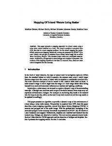
Figure 6 below shows the model of direct sequence spread binary PSK system [8].
2) Length: Short code: Nc.Tc = Ts Long code: Nc.Tc >> Ts 3) Correlation: The correlation between two sequences x(t) and y(t) is the complex inner product of the first sequence with a shifted version of the second sequence. The correlation is called 1) an autocorrelation if the two sequences are the same, 2) a crosscorrelation if they are distinct, 3) a periodic correlation if the shift is a cyclic shift, 4) an aperiodic correlation if the shift is not cyclic, and 5) a partial-period correlation if the inner product involves only a partial segment of the two sequences [7]. 4) Autocorrelation: The auto correlation function for the periodic wave is defined as number of agreements less number of disagreements in a term by term comparison over one full period of sequence with cyclic shift (position τ) of the NcTc/2 sequence itself:
Figure 6: Model of Direct sequence spread binary PSK system
Since both spread spectrum and BPSK modulation are linear operation, we can switch their order.
III. IMPLEMENTATION OF RADAR MODEL IN MATLAB/SIMULINK A. Radar Transmitter-Receiver Scheme
Ra(τ) = ∫pn(t).pn(t+τ).dt -NcTc/2
128 | P a g e
Ami Munshi , Srija Unnikrishnan / International Journal of Engineering Research and Applications (IJERA) ISSN: 2248-9622 www.ijera.com Vol. 2, Issue 3, May-Jun 2012, pp.126-132 4) IF up conversion We use general mixer block from RF block set to up convert the BPSK baseband modulated signal to 70 MHz intermediate frequency.
Figure 7: Model of Spread Spectrum Radar
Figure 7 shows the basic architecture of radar using spread spectrum modulation technique. Baseband part of the Transmitter Section mainly consists of pulse generation, spreading the data using PN sequence and its modulation (BPSK). The output of BPSK modulated baseband signal is up-converted to the intermediate frequency of 70MHz with the help of an up-converter mixer. In RF Subsystem, the signal is again up-converted to RF level of 2.1 GHz using RF mixer. The target can be modelled using the basic radar equation and there is the provision of changing target cross section, target distance [9]. At the receiver front end, the received signal is down converted to the IF level (i.e. 70 MHz). Autocorrelation is the important part of the system that provides uniqueness to this Radar system. The first operation of autocorrelation block is bit by bit synchronism of the received and transmitted IF and then bit by bit multiplied, integrated and dumped. This auto correlated value represents the presence of target and the delay represents the target distance from the transmitter antenna [9].
5) RF subsystem The signal is again up-converted to RF level of 2.1 GHz using RF mixer. The RF signal is then band limited using band pass-pi filter. The band limited signal is then amplified using S-amplifier [9]. The o/p of RF subsystem is then transmitted as shown in Figure 8. C. Radar Receiver in Simulink 1) RF subsystem At the receiver front end, the received signal is down converted to the IF level (i.e. 70 MHz). IF signal is again band limited using 70MHz band pass-pi filter and once again amplified by an amplifier as shown in Figure 9.
B. Radar Transmitter in Simulink 1) Generating binary data stream By using Bernoulli binary generator block in the communication tool box, we can generate binary data stream of 250bps. By adjusting the parameters like M- ary number, initial seed, sample time and output data type, we can achieve the fixed binary stream. In a real time scenario, this data stream is supplied by application that will generate information to be transmitted [10]. 2) Generating PN sequence By using PN sequence generator block in the communication tool box, we can generate PN sequence of 4Kbps data rate. By adjusting the parameters like generator polynomial, initial states, sample time and output data type, we can achieve Pseudo Noise code. 3) Baseband modulation By using BPSK modulator baseband block in the communication tool box, we modulate the spread signal. We need to adjust parameter like phase offset and samples per symbol. This is shown in Figure 8.
Figure 8: Implementation of Spread Spectrum Radar Transmitter in Simulink
D. Autocorrelation and Error calculation block
129 | P a g e
Ami Munshi , Srija Unnikrishnan / International Journal of Engineering Research and Applications (IJERA) ISSN: 2248-9622 www.ijera.com Vol. 2, Issue 3, May-Jun 2012, pp.126-132 Autocorrelation is the one of the vital part of the system that provides uniqueness to this Radar system. As shown in Figure 10, the Align Signals block aligns a signal with a delayed, and possibly distorted, version of itself. The block is particularly useful when you want to compare a transmitted and received signal to find the bit error rate, but do not know the delay in the received signal. The Error Rate Calculation block compares input data from a transmitter with input data from a receiver. It calculates the error rate as a running statistic, by dividing the total number of unequal pairs of data elements by the total number of input data elements from one source. This block produces a vector of length three, whose entries correspond to: the error rate the total number of errors, that is, comparisons between unequal elements and the total number of comparisons that the block made [11]. The auto correlated value obtained from the align signal block represents the presence of target and the delay represents the target distance from the transmitter [9].
Figure 9: Implementation of Spread Spectrum Radar Receiver in Simulink
IV.
SIMULATION RESULTS
A. At the transmitter end The following figures demonstrate simulation results for Radar transmission system. The results are displayed in the form of snapshots of scope signals. These figures demonstrate we can know easily what happens exactly inside a Radar transmitter. The input stream is generated from a Bernoulli generator. This is presented in Figure 11. It has a data rate of 250bps.
Figure 10: Delay and Error calculation between the transmitted and received sequence
130 | P a g e
Ami Munshi , Srija Unnikrishnan / International Journal of Engineering Research and Applications (IJERA) ISSN: 2248-9622 www.ijera.com Vol. 2, Issue 3, May-Jun 2012, pp.126-132
Figure 11: Binary data generated by Bernoulli Generator
Figure 14: DSSS O/P Unipolar Form
Figure 12: PN sequence generator
Figure 15: Baseband Demodulated O/P
The Pseudo Noise code is generated from a PN sequence generator. This is presented in Figure 12 and it has a data rate of 4Kbps. Direct Sequence Spread signal is generated by converting the input data and PN sequence into NRZ Polar form and multiply the resultant data. This is shown in Figure 13. Then the polar product of I/P data and PN sequence is again converted in unipolar form as shown in Figure 14 and then given to the BPSK Baseband Modulator. The DS-BPSK signal is then up converted and transmitted.
B. At the receiver end DSSS O/P waveforms (Figure 13) and Baseband Demodulated O/P waveforms (Figure 16) are auto correlated at the receiver to find the delay and the error between the transmitted and received sequence. 1) Delay Calculation It is observed that if target introduces a delay of two clock cycles, there is a delay of 0.5ms between transmitted and received DSSS signal. This delay can be multiplied to the velocity of light to obtain the distance of target from the Radar. 2) Error Calculation With the given design, it is observed that if 4*10 4 symbols are compared, then, 98 symbols are in error giving the error rate of 0.00245
Figure 13: DSSS O/P Polar Form
Figure 16: Baseband Demodulated O/P Polar Form
131 | P a g e
Ami Munshi , Srija Unnikrishnan / International Journal of Engineering Research and Applications (IJERA) ISSN: 2248-9622 www.ijera.com Vol. 2, Issue 3, May-Jun 2012, pp.126-132 Conclusion and Future Work The work presented here gives implementation of Transmitter and Receiver for Radar system using Matlab/Simulink. Without using mathematically complex blocks, we have designed and tested a Radar transmitter and Receiver in Matlab/Simulink. In the design presented, we have formed target block using delay elements. In future, we aspire to improvise on the target block design. In addition we would also like to observe the error produced by introduction of AWGN channel.
REFERENCES [1] Kopp, Carlo. Air Power Australia. February 9, 2012. http://www.ausairpower.net/OSR-0597.html (accessed February 13, 2012). [2] Meel, J. "De Nayer Instituut." October 1999. sssmag.com/pdf/Ss_jme_denayer_intro_print.pdfSimilar (accessed February 15, 2012). [3] Duke, Peter Smith. Direct sequence spread spectrum modulation for utility packet transmission in under water acoustic communciation network . Thesis, Monterey, California: Naval Postgraduate School, September 2002. [4] Y. Ayogi, T. Fukuchi, H. Endo, M Kusunoki, Y. Iso, K. Inoue, H Ishizhu, R. Kohono. "76GHz Spread Spectrum Radar for Autonomous Intelligent Cruise Control." Intelligent Transportation System, 1997. ITSC '97., IEEE Conference . Boston, MA , USA : IEEE, 1997. 677-682. [5] Matco Burgor-Garcia, Juan Sanmartin-Jara, Felix PerezMartinez,Juan A. Retamosa. "Radar Sensor using Low Probabilityof Interception SS-FH Signals." Aerospace and Electronic Systems Magazine, IEEE , 2000: 23-28. [6] Jin Sam Kwak, Jae Hong Lee. "Infrared Transmission for Intervehicle Ranging and Vehicle-To-Roadside Communication Systems Using Spread-Spectrum Technique." IEEE Transactions on Intelligent Transportation Systems, 2004: 12-19. [7] T Helleseth, P. V. Kumar. "Pseudonoise Sequences ." In Mobile Communications Handbook. Boca Raton: CRC Press, 1999. [8] Haykin, Simon. Digital Communication. New Delhi: Wiley India(P.) Ltd, 2007 [9] Soumyasree Bera, Debasish Bhaskar, Rabindranath Bera. www.ursi.org. 2011. www.ursi.org/proceedings/procGA11/ursi/F05-4.pdf (accessed February 27, 2012). [10] Kanna, Ravikanath. Design of Zigbee Transmitter Receiver IEEE 802.15.4 using Matlab/Simulink. Masters Thesis, Rourkela, Odhisha: National Institute of Technology, 2011. [11] Mathworks. 2012. www.mathworks.com/help/toolbox/comm/ref/alignsigna ls.html (accessed March 5, 2012).
132 | P a g e