waveforms by using stereo audio codec of the kit. Keywords: DSP starter kit ... proposed signal generator the lower frequency range is not limited by the external ...
P.V. Ingole et al
IJCSET | March 2011 | Vol 1, Issue 2,95-98
Implementation of Signal Generator (DSP) Using TMS 320 C 6713 DSK P.V. Ingole, A. K. Sapkal , G.G. Sarate , S. R. Hirekhan Instrumentation and DSP Laboratory, Electronics and Telecommunication Engineering Department, Sant Gadge Baba Amravati University, Government College of Engineering Amravati. (M. S.), India.
before, signal processing by DSP depends on program algorithm given from user to the DSP processor. The process of writing a program in the DSP processor is as same as writing a program in other processors, which is using the machine language or assembler. As an alternative, we can also use C language to program the DSP processor. To development an application with DSK, Texas Instrument provides software called Code Composer Studio (CCS). CCS is software that is used for interfacing user and the DSP board. CCS provides a work environment that contains all of the tools needed to program the DSP processor [2]. The tools are integrated with the CCS. Code Composer Studio is flexible software that can work together with popular software, such as MATLAB, Lab View, Visual Basic, etc.
ABSTRACT TMS 320 C 6713 DSK is used for the implementation of signal generator (DSP). The DSP processor TMS320C6713DSK with Code Composer Studio has been used to generate the signal waveforms and is used for interfacing user and the DSP board. A look-up table method has been used to generate signal waveforms and frequencies as well as amplitude of waveforms are independently adjustable. The user can program required waveform, amplitude, and frequency of the signal. The DSP processor has also been programmed to produce amplitude modulated signal. Simultaneously we can produce two different waveforms by using stereo audio codec of the kit. Keywords: DSP starter kit (DSK), Texas Instrument (TI), Digital Signal Processor (DSP), Code Composer Studio (CCS).
I.
II. THE TMS320C6713 DSK
INTRODUCTION
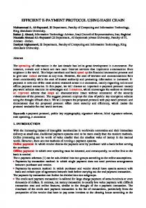
The TMS320C6x are the first processors to use velociTI architecture, having implemented the VLIW (Very Long Instruction Word) architecture. The TMS320C62x is a 16-bit fixed point processor and the ‘67x is a floating point processor, with 32-bit integer support. The C6713 DSK is a low-cost standalone development platform that enables users to evaluate and develop applications for the TI C67xx DSP family. [3] The simplified architecture of TMS320C6713 is shown in the Figure.1 below. The processor consists of three main parts: CPU, peripherals and memory. The CPU contains program fetch unit, Instruction dispatch unit, instruction decode unit. The CPU fetches advanced verylong instruction words (VLIW) to supply up to eight 32-bit instructions to the eight functional units during every clock cycle. The first bit of every 32-bit instruction determines if the next instruction belongs to the same execute packet as the previous instruction, or whether it should be executed in the following clock as a part of the next execute packet. The CPU contains two general purpose register files A and B. These can be used for data or as data address pointers. Each file contains sixteen 32-bit registers. [11] The CPU features two sets of functional units. Each set contains four units and a register file. Each functional unit has two 32-bit read ports for source operands and one 32-bit write port into a general purpose register file. The memory system of the TMS320C671x series processor implements a modified
In measurement and instrumentation system signal generators play a significant role where analogue and digital systems are characterized by different types of waveforms. This signal generator is based on a digital signal processor to generate signals between 0.002 Hz and 15 kHz. In the proposed signal generator the lower frequency range is not limited by the external components but the upper frequency range is limited due to bandwidth of stereo codec AIC23. In this paper we try to discuss implementation of signal generator which could function for various signal generators, DSP board TMS 320 C 6713, process of code building, methodology and signal generator applications. The TMS320C6713DSK has main features such as fast data access, fast computation, numerical fidelity, fast execution control which make it suitable for various applications.[9][10] Texas Instrument (TI) DSP starter kit TMS320C6713DSK, which consists of a TMS320C6713 DSP chip and stereo codec TLV320AIC23, is used in design. The design algorithms are processed by DSP and the stereo codec TLV320AIC23 consisting of an analogue-to-digital converter (ADC) and a digital-to-analogue converter (DAC). [1] The processing of the signal is simple, the analogue signal coming from port mike in or line in then, it is sampled to digital signal by the codec. Then the sampled signal will be processed digitally by the DSP. This signal processing depends on how the user programs the DSP board. Then, the output signal will be release through line out or headphone. As mentioned
95
P.V. Ingole et al
IJCSET | March 2011 | Vol 1, Issue 2,95-98
Harvard architecture, providing separate address spaces for instruction and data memory. [10] The development tool used for TMS320C6713DSK is TI Code Composer Studio (CCS).
JTAG interface; as an alternative, the executable can be converted to a special form and loaded to a memory external to the DSP, from which the DSP itself will boot. The first approach is typically used during the DSP development phase, while the second approach is more convenient during system exploitation. Three tools, namely compiler, assembler, and linker, are used to generate executable code from C/C++ or assembly source code. Figure 3 shows their use in the codebuilding process on TI DSPs. [5]
Fig.1. Simplified block diagram of TMS320C67xx core architecture
It offers robust core functions with easy-to-use configuration and graphical visualization tools for system design. Programming in C is used to write for the application. It is then compiled, linked and executed by the CCS. With the efficiency of the C programming code, the desired applications are to be made programmable and user-friendly. [6] III. CODE-BUILDING PROCESS
Fig.3. Generic code-building processing
IV. METHODOLOGY
The DSP code-building process relies on a set of software development tools, typically provided by DSP manufacturers. Figure2. Shows the main elements and tools needed for the code-building process
Beside a source code to program a TMS 320 C 6713 processor, BIOS configuration file and linker command file need to be added into the project. The Board Support Library is a software library that provides a C-language interface for configuring and controlling all on-board devices. Individual Application Programming Interface (API) is used to represent the devices on board. Hence, appropriate API to be included on source program as per the hardware features to be used. For generation of a variety of signal a look-up table method has been used to generate. The samples of the signal to be generated are pre-calculated using a known algorithm over one cycle and stored in the digital memory. The preferred signals are retrieved from the look–up table stored in the memory using the proper number of samples within one cycle. The analogue signal is generated by passing the digital output through an inbuilt digital-to-analogue converter (TLV320AIC23) in the DSP starter kit. Different types of signals that can be generated are sine wave, square wave, triangle wave, periodic arbitrary waveforms, pseudo random noise sequence and amplitude modulated signal. When generating waveform, three aspects are considered; namely type of waveform, amplitude and frequency of waveform. These waveforms are generated using different algorithms.
Fig2. Main elements of the code building process.
Source files are converted to object files by the compiler and the assembler. Archiver tools allow the creation of libraries from object files; these libraries can then be linked to object files to create an executable. The executable can be directly downloaded from the IDE to the target DSP via a
96
P.V. Ingole et al
IJCSET | March 2011 | Vol 1, Issue 2,95-98
Frequency and amplitude of the waveforms can be varied by changing the algorithms too. It is possible to obtain two synchronized signals of different types simultaneously. The operation of the signal generator is very simple. The user has to enter the three essential parameters, namely type, frequency and amplitude of the desired signal at the start of the operation. [8] Figure4. Consider typical periodic arbitrary signal waveforms as shown in figure4.
Where fo = output frequency fs = sampling frequency Sample/cycle = number of sample in one cycle The sampling frequency is the sampling rate of the codec of DSP processor, which can be varied using the appropriate API. The sampling rate used here is 8 kHz. For sine wave, as shown in Figure 6, can be generated by sin ( ) function. The algorithm used is as below: Sine wave = a*sin (2* PI * (sample/cycle))
(3)
Where a = amplitude of waveform Sample/cycle = number of sample in one cycle
. Fig 4. Arbitrary waveforms.
The above signal waveform is a mixture of sine waves with a range of frequencies. These can be obtained by defining the waveform through the following equation: 0