Nigerian Journal of Technology (NIJOTECH) Vol. 34 No. 2, April 2015, pp. 342 – 354 Copyright© Faculty of Engineering, University of Nigeria, Nsukka, ISSN: 1115-8443 www.nijotech.com
http://dx.doi.org/10.4314/njt.v34i2.19
IMPLEMENTATION OF SPATIAL DOMAIN HOMOMORPHIC FILTERING ON EMBEDDED MOBILE DEVICES U. A. Nnolim* DEPARTMENT OF ELECTRONICS ENGINEERING, UNIVERSITY OF NIGERIA, NSUKKA, NIGERIA E-mail address:
[email protected] ABSTRACT
This paper describes the analysis of the Homomorphic filtering algorithm, the equivalency between the frequency and spatial-domain methods and the implementation of low-pass and high-pass spatial domain Homomorphic filter in low power embedded devices. It is shown that the Homomorphic filter in the spatial domain combines the sensitivity of local/neighbourhood operations in addition to Laplacian-type edge enhancement, averaging operation of illumination intensity estimation, in addition to dynamic range compression associated with frequency-domain Homomorphic filters. A qualitative and quantitative comparison of the image results confirms the validity of the theoretical approach and advantages for digital hardware implementation. The developed filters are implemented on a Java-enabled mobile phone and form a low cost embedded image processing enhancement system. Keywords: Spatial domain homomorphic filtering, contrast enhancement, image processing, java programming 1. INTRODUCTION There is a lot of background literature on frequencydomain Homomorphic filtering [1-2]. However, such a scheme is too costly and complex to implement in digital and embedded hardware for real-time operation. In contrast, there is very little background information on practical implementation of spatialdomain Homomorphic filtering relative to its frequency domain counterpart. However, though modern computer systems are powerful enough to implement such systems, portable embedded devices such as mobile phones are limited by the power supply. Increased use of multipliers and dividers leads to increased power consumption in digital hardware devices, which results in more power drawn by the battery [3]. Thus, increase in computation places demands on the battery of such devices, leading to shorter battery life-span. As a result, the goal of digital hardware design is to minimize the number of multiplication and division operations performed in the target device [3-9]. Frequency domain Homomorphic filtering is computationally intensive and is a function of image size, which increases demands on limited memory on the mobile device. However, spatial domain Homomorphic filtering is relatively independent of image dimensions and viable architectures have been * Tel: +234-809-233-6901
developed to reduce demands on hardware [4-9]. The spatial domain avoids the use of frequency transforms in addition to large-scale scalar and vector multiplications. Additionally, multiplierless architectures for spatial filter kernels have been developed in the literature [4-6, 8-9]. This paper combines the mathematical theory and equivalence of the spatial-domain filtering method with the practical implementation of the developed algorithm on physical devices. It also validates the actual image results obtained from the experimentation of the theory. The derivation is important because of the wide range of applications that can benefit from real-time implementations of Homomorphic filters, which has been hindered in the past by computational complexity of the more, wellknown frequency-domain technique. The work described is in two parts, the first part forms the theoretical background and analysis of mathematically derived filter kernels evidenced by simulation. The second part focuses on the practical implementation of the algorithm on a physical embedded mobile phone device 2. ANALYSIS OF HOMOMORPHIC FILTERING Homomorphic filtering is a logarithm-based image enhancement procedure used to highlight details in an
U. A. Nnolim
IMPLEMENTATION OF SPATIAL DOMAIN HOMOMORPHIC FILTERING ON EMBEDDED MOBILE DEVICES
image scene [1-2, 7-9]. It achieves this task by providing simultaneous dynamic range compression and contrast enhancement [1-2]. It uses logarithm and frequency domain transforms and linear (exponential) operator to recover the dynamic range after processing [1-2]. The mathematical principle behind Homomorphic filtering theory is rooted in the illuminationreflectance approximation model of image scenes [1-2, ), is a 9-12]. In this model, the image, ( multiplicative combination of the illumination ), (i.e. the dark regions of the image component, ( consist of slow variations or low frequency components) and the reflectance component, ( ), (i.e. the bright regions of the image which consist of rapid and pronounced variations or high frequency components)[1-2, 9]. The illumination is the light absorbed while the reflectance is the light component reflected by the image [1-2, 9]. The assumption is that the illumination component varies slowly, unlike the reflectance component [1-2, 9]. ( ) ( ) ( ) (1) The spatial-domain method of the Homomorphic filter is derived from the Frequency-domain method to prove its equivalency. Thus, the frequency-domain Homomorphic filtering technique is mathematically defined as; ( ( )+) * * | ( )|+ ( ) ( ) ( ) is the where ( ) is processed image, frequency domain high pass filter (HPF), while u and v are the frequency coordinates. The symbols and are the forward and inverse Fourier transform operators respectively. For the frequency domain transform of the image in the current domain is non-separable due to the multiplicative result of the illumination and reflectance components. This is the reason for the logarithm transform to allow separation of the reflectance and illumination components. And the logarithmic transformation can be given in the mathematical form [9] as; | ( )| |( ) ( )| |( )| | ( )| ( ) After the logarithmic operation, the image is then ready to be filtered either in the frequency or spatial domain as required. Returning to (2), the high-pass filter is related to a low-pass filter by the equation [9]: ( ) ( ) (4) Therefore, ( ( )+) * * | ( )|+ ( ) (
* * | (
)|+ (
(
))+)
Nigerian Journal of Technology,
( )
(
)
(
(
*, * | (
)|+
* | (
)|+-
(
)+)
( )
) (
*, * | (
)|++
* * | (
)|+-
(
)+)
( ) ( ) ( ) * ( ) ( )+ and Where *+ denotes convolution [9]. Thus, (8) is the mathematical expression for the spatial domain Homomorphic filtering using a low-pass spatial filter and image subtraction [9] Thus, going back to (3) and )|, (8) becomes; substituting for | ( ( | ( ) ( )| * | ( ) ( )| ( )+) ( ) ( ) Leading to: ( ) ( | ( )| ( )+) | ( )| *, | ( )| | ( )|( ) Since a low-pass filter is used here, the high frequency components, namely, the reflectance ), is eliminated in the filtering [9]. component, ( This leads to: ( | ( )| | ( )| | ( )|) ( ) ( ) Resulting in ( | ( )|) ( ) ( ) ( ) This completes the spatial domain Homomorphic process since the illumination component has been filtered out of the image. An equivalent high-pass spatial filter for the Homomorphic filter [9] is also shown as: ( | (
)| * | (
)|
(
)+)
( )) ( | ( )| ( ) ( ) From here the equivalency between the methods is evident (in that the reflectance is obtained in both cases) in (11) and (14), resulting in a brighter, more detailed image with the high frequency components [9]. The high-pass filter eliminates the illumination ) directly, leaving just ( component, ( ) as derived in (15).
(
)
(* | (
)|
| (
)|+
(
))
( ) ( ) ( ) However, an image with only the reflectance is not balanced and thus the need for the high boost emphasis parameter added to suppress rather than eliminate the illumination component of the image and enhancing the reflectance component in the image [1-2, 9]. The frequency-domain high boost emphasis ( ) is defined as; filter (HBEF), ( ) ( ) ( ) ( ) Where and are the high and low gain of the filter response [1-2, 9]. In the spatial domain, the high ( ), is defined boost emphasis filter (HBEF), as; ( ) (17) ( | (
)|)
Vol. 34, No. 2, April 2015
343
U. A. Nnolim
IMPLEMENTATION OF SPATIAL DOMAIN HOMOMORPHIC FILTERING ON EMBEDDED MOBILE DEVICES
(a)
(b)
(c)
(d)
Figure 1 Low-pass filter in the (a) frequency domain (b) spatial domain and High-pass filter in the (c) frequency domain (d) spatial domain Spatial Domain Lowpass Gaussian kernel with N = 5 and sigma = 1.0489
Spatial Domain lowpass Gaussian kernel with N = 5 and sigma = 1.0489 0.16 0.14 0.2 0.12 0.15 magnitude
magnitude
0.1 0.08
0.05
0.06
0 5
0.04
4
0.02 0
5 4
3
3
2 1
1.5
2
2.5
3 N
3.5
4
4.5
5
N
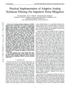
Figure 2(a) 1D Plot of Gaussian low-pass filter in the spatial domain
( )
( | (
) (* | (
)|
)| | (
(
))
)|+
(
( ))
)
( ) ( ) ( ) ( ) The result in (20) provides a more balanced image and flexibility in filter tuning and illumination estimation in the process. This result is the mathematical expression of Homomorphic high-boost filtering for continuous 2D image signals. For discrete 2D image signals, (20) [9] becomes; ( | ( )| | |) ( ) ( ) ( ) In (21), n and m are the coordinates of the discrete variables encapsulated in the digital image signal. Figure 1 shows the 2D plots of the frequency domain filters and their spatial domain counterparts [9]. The spatial domain variants of the frequency domain filters are obtained from the inverse Fouriertransformed (centered) frequency-domain filters. Figs 2- 5 show the 1D and 3D plots of the derived spatial ( | (
)|
|
|)
Nigerian Journal of Technology,
2 1
1
N
Figure 2(b) 3D Plot of Gaussian low-pass filter in the spatial domain
Where N = spatial filter kernel size and is the gain or amplitude of the filter function (in this case, the centre pixel of the spatial filter). Thus the end results of the equations from (11) to (13) become: (
0.1
and frequency domain low-pass and high-pass filters. The frequency domain versions are dependent on the dimensions of the image to be filtered (256 × 256 in this case) and Homomorphic filters are usually implemented in the frequency domain using such filters. However, this presents a resource issue when the Homomorphic filter has to be implemented in digital hardware systems for real-time applications creating the need for compact, spatial domain Homomorphic filtering solutions [7-9]. The common feature in both the low-pass and high pass filters in the spatial domain is that of the centre pixel being the maximum. In the spatial domain, both the high-pass and low pass filters can then be used for the Homomorphic filtering process in a straightforward manner, using convolution. No approximation of the frequency filters have been made for the spatial kernels. However, the spatial domain equivalent in Figure 1(b) and (d) provide insight into possible spatial filter approximations for the filter kernel to be used.
Vol. 34, No. 2, April 2015
344
U. A. Nnolim
IMPLEMENTATION OF SPATIAL DOMAIN HOMOMORPHIC FILTERING ON EMBEDDED MOBILE DEVICES
Frequency Domain lowpass Gaussian kernel with N = 255 and sigma = 5
0.9 0.8
magnitude
0.7 0.6 0.5 0.4 0.3 0.2 0.1 0
0
50
100
150
200
250
N
Figure 3(a): 1D Plot of Gaussian low-pass filter in the frequency domain
Figure 3(b): 3D Plot of Gaussian low-pass filter in the frequency domain Spatial Domain Highpass Gaussian kernel with N = 5 and sigma = 1.0489
Spatial Domain Highpass Gaussian kernel with N = 5 and sigma = 1.0489 0.9 0.8 1
0.7
0.5
magnitude
magnitude
0.6
0.4
0.5
0
0.3 0.2
-0.5 5
0.1
4 0 -0.1
5 4
3
3
2 1
1.5
2
2.5
3 N
3.5
4
4.5
5
Figure 4(a): 1D Plot of Gaussian high-pass filter in the spatial domain
A trivial filter of size 3x3 can be directly derived from the most prominent kernel values closest to the centre pixel. This can be then convolved with the image to be processed and subtracted from the original image to obtain an image with not only increased detail and contrast but also enhanced edges. 3. EXPERIMENTAL RESULTS Figure 6 shows an approximated 5x5 Gaussian kernel, which is used in the spatial domain Homomorphic filter and Multi-Scale Retinex with Colour Restoration (MSRCR) enhancement method [11-12]. The 5x5 kernel makes both processes faster and the speed of computation is more pronounced with increased image size. When the kernel is increased in size, it assumes the form of the spatial-surround Retinex [12] that is at the heart of the MSRCR method. Nigerian Journal of Technology,
N
2 1
1
N
Figure 4(b): 3D Plot of Gaussian high-pass filter in the spatial domain
The kernel speeds up the convolution and also retains the colour rendition and colour constancy properties of the MSRCR. A sample of images used in the experiments are shown in Figure 7(a). In Figure 7(b), the image results of the swan image obtained from Homomorphic filtering in the frequency and spatial domains are observed for visual comparison. It is difficult to observe any major difference in the images. However, the image histograms in Figure 8 clearly show the differences between the enhanced images in different domains. It is evident that the distribution in the spatial domain is more enhanced in that the distribution of pixels has now moved more to the right relative to the original image pixel distribution. Thus, enhanced image is lighter with higher pixel values corresponding to the rightward shift in the pixel intensities. Vol. 34, No. 2, April 2015
345
IMPLEMENTATION OF SPATIAL DOMAIN HOMOMORPHIC FILTERING ON EMBEDDED MOBILE DEVICES Frequency Domain Highpass Gaussian kernel with N = 255 and sigma = 5 1 0.9 0.8
magnitude
0.7 0.6 0.5 0.4 0.3 0.2 0.1
0
50
100
150
200
250
N
Figure 5(a): 1D Plot of Gaussian high-pass filter in the frequency domain
Figure 5(b): 3D Plot of Gaussian high-pass filter in the frequency domain
(a)
(b) Figure 6 (a) 5x5 spatial filter kernel (b) 400×400 spatial filter kernel Nigerian Journal of Technology,
U. A. Nnolim
The frequency domain method is enhanced as well but the rightward shift is less pronounced than that of the spatial domain method. All of the R, G and B components are shifted in each case but the overall shift is more evident in the spatial domain-processed image. Figure 9 compares the results of the spatial domain Homomorphic filtering with the frequency domain method and the MSRCR. Once more, it is hard to see any noticeable changes in the image results from the different methods when evaluated visually. Thus upon inspection of the image histograms in Figure 10, it can be clearly seen that the methods affect the pixel intensity distribution in different ways. As was seen in Figure 7(b), the spatial domain gives the most balanced effect since the frequency domain method is skewed more to the left while the MSRCR is skewed too much to the right. Furthermore, when statistical measures are used to evaluate the degree of enhancement, it is appropriate to use such quantities as kurtosis, skewness and moments of the image distribution to give a better understanding of the image properties. The use of these measures also stems from the use of these measures for mapping an image to a new dynamic range for colour enhancement as reported in the literature [13]. In the following tables, some statistical measures [14] are presented to attempt to quantitatively evaluate the visual results of the enhanced images. The terms used are defined as follows. The standard deviation measures the spread of the distribution. Thus images with more contrast are more spread out in terms of their histogram distribution and have higher standard deviation. The skewness measures the symmetry of the distribution around the mean. The distribution is biased more to the right of the mean if the skewness is positive and biased to the left if negative. A zero value implies a symmetrically centered distribution around the mean (normal distribution). The kurtosis value measures the peakedness of the distribution. A kurtosis value less than 3 implies the distribution has a narrower peak than the normal distribution. A value greater than 3 has a broader peak than the normal distribution. In Table I, the initial statistical measurements of the R, G, B channels of the colour image are shown. Table II shows the R, G, B values after filtering with the Gaussian spatial filter. This is the same in Table III as can be seen for the frequency domain filter. The enhanced image has a higher standard deviation (more contrast) and the histogram is more biased to the right due to positive skewness. Vol. 34, No. 2, April 2015
346
IMPLEMENTATION OF SPATIAL DOMAIN HOMOMORPHIC FILTERING ON EMBEDDED MOBILE DEVICES
U. A. Nnolim
Figure 7(a) Sample of utilized RGB colour images with varying dimensions (from top left to bottom right: House, Swan, Girl and Cathedral images)
(a)
(c) Figure 7(b) (a) original image (b) frequency domain Homomorphic filtered image (c) spatial domain Homomorphic filtered image
(b) Nigerian Journal of Technology,
Vol. 34, No. 2, April 2015
347
U. A. Nnolim
IMPLEMENTATION OF SPATIAL DOMAIN HOMOMORPHIC FILTERING ON EMBEDDED MOBILE DEVICES Original RGB histogram of colour image
RGB histogram of frequency domain Homomorphic processed colour image
5000
4000
3000
2000
1000
0
50
100
150 200 pixel intensity values
250
300
2500
Frequency of occurrence of pixel intensity
6000
0
RGB histogram of spatial domain Homomorphic processed colour image
1200
Frequency of occurrence of pixel intensity
Frequency of occurrence of pixel intensity
7000
1000
800
600
400
200
0
0
50
100
(a)
150 200 pixel intensity values
(b)
250
300
2000
1500
1000
500
0
0
50
100
150 200 pixel intensity values
250
300
(c)
Figure 8 Histograms of (a) original image (b) frequency filtered image (c) spatial domain filtered image
(a)
(b)
(c)
Figure 9 Comparison of (a) frequency domain (b) spatial domain filtered image (c) MSRCR processed image Nigerian Journal of Technology,
Also, the kurtosis value is less than 3 thus the peak is narrower implying that higher frequencies are more pronounced. The same is seen in the frequency domain. The MSRCR in Table III has the highest standard deviation and central moment values and thus has the highest variance (contrast) evidenced in the visual colour contrast in the enhanced image in Fig 5(c). For further checking, we utilize the global contrast [15] and colourfulness parameters [16] and use ratios of the final to initial values to determine how enhanced or degraded the images are. Though these measures give a quantitative measure, they still do not form a complete picture of the aesthetic or colour forms of an image as understood by humans. The results of four image samples enhanced with the algorithm in the spatial domain are shown in Table V. The spatial domain filter offers the least complexity when compared with the frequency domain homomorphic filter and the MSRCR algorithm, while yielding satisfactory and comparable results to the frequency domain. The processing times for both spatial domain and frequency domain homomorphic filters are shown in Table VI while Figure 11 shows the plot of simulation times of both spatial and frequency domain versions. The comparison plot of the operation of the algorithm in both the spatial and frequency domains shows a huge speed up when operating in the spatial domain. Since the spatial domain variant is independent of image dimensions, its speed of operation is fairly constant. The only factor that affects the spatial domain method is the size of the filter window kernel. Since a filter size of 3×3 is used throughout, results are fairly constant. Vol. 34, No. 2, April 2015
348
U. A. Nnolim
IMPLEMENTATION OF SPATIAL DOMAIN HOMOMORPHIC FILTERING ON EMBEDDED MOBILE DEVICES RGB histogram of frequency domain Homomorphic processed colour image
RGB histogram of spatial domain Homomorphic processed colour image
1200
RGB histogram of MSRCR processed colour image
2500
8000
800
600
400
200
Frequency of occurrence of pixel intensity
Frequency of occurrence of pixel intensity
Frequency of occurrence of pixel intensity
7000 1000
2000
1500
1000
500
6000 5000 4000 3000 2000 1000
0
0
50
100
150 200 pixel intensity values
250
0
300
0
50
100
150 200 pixel intensity values
250
0
300
0
50
100 150 pixel intensity values
200
250
(a) (b) (c) Figure 10 Histograms of (a) frequency domain (b) spatial domain filtered image (c) MSRCR processed image Table I. Original image (R G B Channels) Image Channels
2nd Central Moment
Standard Deviation
Skewness
Momental Skewness
Kurtosis
R
0.0200
0.1413
0.9775
0.4888
3.6238
G
0.0152
0.1234
1.8609
0.9305
7.2224
B
0.0129
0.1136
2.1294
1.0647
8.3197
Table II. Gaussian spatial filter (5x5 filter kernel) Image Channels
2nd Central Moment
Standard Deviation
Skewness
Momental Skewness
Kurtosis
R G B
0.0476 0.0291 0.0239
0.2182 0.1706 0.1546
0.0245 0.7558 0.8661
0.0123 0.3779 0.4330
2.1078 3.2086 3.6072
Table III. Final image MSRCR (5x5 filter kernel) Image Channels
2nd Central Moment
Standard Deviation
Skewness
Momental Skewness
Kurtosis
R G B
0.0752 0.0602 0.0480
0.2743 0.2453 0.2190
-0.5785 -0.1306 -0.0093
-0.2892 -0.0653 -0.0046
2.1629 2.0913 2.3972
Table IV. Final image HSI frequency domain filter Image Channels
2nd Central Moment
Standard Deviation
Skewness
Momental Skewness
Kurtosis
R G B
0.0580 0.0373 0.0310
0.2408 0.1932 0.1761
0.1929 0.9118 1.0604
0.0964 0.4559 0.5302
2.1922 3.6312 4.1620
Table V. Colourfulness & Contrast values for images enhanced with spatial Homomorphic filter Colour image Swan Girl House Cathedral
Colourfulness (initial/final) 15.6330/21.3244 44.1702/54.1058 10.4892/22.0454 35.2780/25.4862
Global Contrast Factor (GCF)(initial/final) 0/6.5343 0/5.9802 0/4.3169 0.0917/6.7922
Relative Colour improvement 1.3641 1.2249 2.1017 0.0917
Relative Contrast improvement Inf Inf Inf 74.0820
Table VI. Processing times for spatial and frequency domain filter Colour Image Girl Swan House Cathedral
Dimensions 256 × 256 513 × 385 512 × 512 768 × 512
Spatial domain processing time(s) 0.058 0.210 0.232 0.371
Nigerian Journal of Technology,
Frequency domainprocessing time(s) 0.914 11.691 16.186 40.826
Vol. 34, No. 2, April 2015
349
IMPLEMENTATION OF SPATIAL DOMAIN HOMOMORPHIC FILTERING ON EMBEDDED MOBILE DEVICES
Figure 11 Plot of processing times for both spatial domain Homomorphic filter and frequency domain filter This does not mean that extremely large images will not take slightly more time for the spatial domain version. Rather, the time will be relatively less compared with the frequency domain version. The Discrete Fourier Transform (DFT) is used in the frequency domain version, and accounts for the bulk of the processing time. Even with the FFT algorithm, the spatial domain variant is much better with regard to processing time.
U. A. Nnolim
embedded target platform is a Nokia Asha smartphone. The software development environment uti ized is the Su Microsystems™ (acquired by Orac e™) NetBea s™, - a d Nokia© SDK , - IDE tools using the Java 2 Micro Edition (J2ME) [19] framework. The functional layout of the system is as shown in Figure 12 while the basic software architecture is shown in Figure 13. The image source can be a picture taken with the camera-phone or already stored on the device. The algorithm engine is interfaced with a file browsing utility program to retrieve and process the static images. Alternatively, the image is captured and processed prior to saving to the device. The latter option is the ideal since the raw image file is not compressed and thus, more of the original data is preserved in the processing prior to saving. However, the second scheme is much more involved. Additionally, another problem in the implementation on a mobile device is that there are no inbuilt logarithmic or exponential functions in the J2ME environment and thus, custom logarithm and exponential functions are also implemented to perform the logarithmic and linear transformation for the homomorphic algorithm on the mobile phone.
4. IMPLEMENTATION ON JAVA ENABLED MOBILE PHONE The implementation of the developed algorithm on an embedded platform is described in this section. The
Acquire Image
Spatial Domain Homomorphic filter
From file/Captured from camera sensor
Display/save store processed image
Image processing unit
Figure 12 Mobile phone image processing
Figure 13 Basic architecture of the application in J2ME Nigerian Journal of Technology,
Vol. 34, No. 2, April 2015
350
IMPLEMENTATION OF SPATIAL DOMAIN HOMOMORPHIC FILTERING ON EMBEDDED MOBILE DEVICES
U. A. Nnolim
.
Figure 14 Mobile phone emulator and IDE environment (image loading stage)
Figure 15 Mobile phone emulator and IDE environment (loaded image)
Nigerian Journal of Technology,
Vol. 34, No. 2, April 2015
351
IMPLEMENTATION OF SPATIAL DOMAIN HOMOMORPHIC FILTERING ON EMBEDDED MOBILE DEVICES
U. A. Nnolim
Figure 16 Mobile phone emulator and IDE environment (Homomorphic filtering option selection) Due to limited memory of the emulator and inability to add custom images to the memory of the emulated mobile phone, only screen shots of the file browsing and image loading are shown. The actual results of the software application are shown in low resolution photos obtained with another camera phone. The Eclipse phone emulator IDE environment with the various stages is shown in Figs. 14-16, while the screen shot of the actual operation of the system on the Nokia Asha™ mobi e pho e p atform is show i Figure 17(a) and (b). 5. CONCLUSION The derivation of the spatial domain method along with the analysis of the theory and its application in practice has been used to verify the utility of the approximated filter kernel. The various derived filter kernels have been tested with over 300 images in both RGB colour and grayscale and results have been more or less consistent. Also, it has been shown that the image-size independent filter kernel is a limit of the spatial surround function used in the MSRCR. Furthermore, image visual results coupled with quantitative measures have been shown to be useful in understanding the degree of enhancement of Nigerian Journal of Technology,
images using enhancement methods.
(a) Vol. 34, No. 2, April 2015
352
IMPLEMENTATION OF SPATIAL DOMAIN HOMOMORPHIC FILTERING ON EMBEDDED MOBILE DEVICES
U. A. Nnolim
International Journal of Computer Science and Information Technology, vol. 2.3(2010), pp. 12 -22, arXiv.1006.1179 [cs.AR]. [4]M. Z. Zhang, V. K. Asari, An efficient multiplier-less architecture for 2-D convolution with quadrant symmetric kernels, INTEGRATION, the VLSI journal, vol. 40, pp. 490–502, 2007. [5]M. Z. Zhang, H. T. Ngo, V. K. Asari, Multiplier-less VLSI architecture for real-time computation of multidimensional convolution, Journal of Microprocessors and Microsystems, vol. 31, pp. 25– 37, 2007. [6]U. A. Nnolim, "A Log-hybrid architecture for tonal correction combined with modified un-sharp masking filter algorithm for colour image enhancement," INTEGRATION, the VLSI journal, vol. 48, pp. 221-229, 2015. [7] U. Nnolim and P. Lee, "Homomorphic Filtering of colour images using a Spatial Filter Kernel in the HSI colour space", IEEE Instrumentation and Measurement Technology Conference Proceedings, 2008, (IMTC 2008) Victoria, Vancouver Island, Canada: IEEE, pp. 1738-1743, 2008.
(b)
Figure 17 Spatial domain Homomorphic filter application running on Nokia phone (a) processed swan image on display (b) file saved to mobile phone. The application of the filter kernel to the Homomorphic filter has reduced the speed and complexity of computation and makes it possible to implement the Homomorphic filter in its current form on portable, low-power embedded hardware devices such as mobile phones. Moreover, this 3x3 filter kernel is computationally efficient and is the most trivial size for an odd-sized spatial filter kernel used in the implementation of the spatial domain filter ported to the mobile phone unit. The results of the implemented system prove the feasibility of the spatial domain Homomorphic filter in digital hardware implementation for low-power devices. 6. REFERENCES [1] R. C. Gonzalez and R. E. Woods, Digital Image Processing, 2 Ed.: Prentice Hall, 2002. [2] R. C. Gonzalez, R. E. Woods, and S. L. Eddins, Digital Image Processing Using MATLAB: Prentice Hall, 2004. [3]C. N. Marimuthu, P. Thangaraj, Aswathy Ramesan, “Low Power Shift a d Add Mu tip ier Desig ”
Nigerian Journal of Technology,
[8] M. Z. Zhang, M.-J. Seow, L. Tao, and V. K. Asari, "A tunable high-performance architecture for enhancement of stream video captured under nonuniform lighting conditions," Journal of Microprocessors and Microsystems, vol. 32, pp. 386 - 393, May 4 2008. , -U
N o im “FPGA Architectures for Logarithmic Co our Image Processi g” Ph D thesis U iversity of Kent at Canterbury, Canterbury-Kent, 2009.
[10]J.-C. Pinoli, "A general comparative study of the multiplicative homomorphic, log-ratio and logarithmic image processing approaches," Signal Processing, vol. Volume 58, pp. 11 - 45, 1997. [11] Z.-u. R. Danial J. Jobson, Glenn A. Woodell, "A Multiscale Retinex for Bridging the Gap Between Color Images and the Human Observation of Scenes," IEEE Transactions on Image Processing, vol. Vol. 6, pp. 965-976, 1997. [12]Z.-u. R. Danial J. Jobson, Glenn A. Woodell, "Properties and Performance of a Center/Surround Retinex," IEEE Transactions on Image Processing, vol. Vol 6., pp. 451 - 462, 1997. [13]V. Patrascu, "Image Enhancement Method using Piecewise Linear Transforms."European Signal Processing Conference, EUSIPCO-2004, Vienna, Austria, pp. 577-580, 2004. [14]U. A. Nnolim, P. Lee, A Review and Evaluation of Image Contrast Enhancement algorithms based on statistical measures, IASTED Signal and Image Processing Conference Proceeding, 2008, Kailua Kona, HI, USA, August 18-20, 2008.
Vol. 34, No. 2, April 2015
353
IMPLEMENTATION OF SPATIAL DOMAIN HOMOMORPHIC FILTERING ON EMBEDDED MOBILE DEVICES [15]Matkovic, Kresimir et al., "Global Contrast Factor-a New Approach to Image Contrast," Proceedings of the 1st Eurographics Conference on Computational Aesthetics in Graphics, Visualization and Imaging, Switzerland, 2005, pp. 159-167. ,
-S Susstru k D Has er “Measuri g Co ourfu ess i Natura Images “ IS&T/SPIE Electronic Imaging 2003: Human Vision and Electronic Imaging VIII, vol. 5007, p.87-95, 2003.
,
-Orac e “NetBea s IDE” Retrieved, Jan 29, 2015.
U. A. Nnolim
,
-Microsoft Corp “Nokia SDK for Java ” (http://developer.nokia.com/resources/download/3518/?id=3 518) Retrieved, Jan 29, 2015.
,
-Orac e “Java P atform Micro Editio (Java ME) ” (http://www.oracle.com/technetwork/java/embed ded/javame/index.html) Retrieved, Jan 29, 2015
(https://netbeans.org/)
Nigerian Journal of Technology,
Vol. 34, No. 2, April 2015
354