Home
Search
Collections
Journals
About
Contact us
My IOPscience
Implementation of stochastic cooling hardware at Fermilab's Tevatron collider
This content has been downloaded from IOPscience. Please scroll down to see the full text. 2011 JINST 6 T08002 (http://iopscience.iop.org/1748-0221/6/08/T08002) View the table of contents for this issue, or go to the journal homepage for more
Download details: IP Address: 180.180.123.49 This content was downloaded on 17/10/2013 at 16:27
Please note that terms and conditions apply.
P UBLISHED BY IOP P UBLISHING FOR SISSA R ECEIVED: May 23, 2011 ACCEPTED: May 23, 2011 P UBLISHED: August 2, 2011
ACCELERATOR
PHYSICS AND TECHNOLOGY AT THE
T EVATRON C OLLIDER R UN II
Ralph J. Pasquinelli Fermilab, PO Box 500, Batavia, IL 60510, U.S.A.
E-mail:
[email protected] A BSTRACT: The invention of Stochastic cooling by Simon van der Meer [1] made possible the increase in phase space density of charged particle beams. In particular, this feedback technique allowed the development of proton antiproton colliders at both CERN and Fermilab. This paper describes the development of hardware systems necessary to cool antiprotons at the Fermilab Tevatron Collider complex. K EYWORDS : Instrumentation for particle accelerators and storage rings - high energy (linear accelerators, synchrotrons); Hardware and accelerator control systems
1 Operated
by Fermi Research Alliance, LLC under Contract No. DE-AC02-07CH11359 with the United States
Department of Energy.
c 2011 IOP Publishing Ltd and SISSA
doi:10.1088/1748-0221/6/08/T08002
2011 JINST 6 T08002
Implementation of stochastic cooling hardware at Fermilab’s1 Tevatron collider
Contents Introduction
1
2
Pickup and kickers
1
3
Preamplifiers
4
4
Recursive notch filters
7
5
Signal transmission
13
6
Power amplifiers
17
7
Equalizers
20
8
Summary
22
1
Introduction
Stochastic cooling system technology at Fermilab has expanded considerably on the initial systems developed at CERN. Cooling systems are utilized for increasing phase space density of 8 GeV antiprotons in three Fermilab antiproton synchrotrons: Accumulator, Debuncher, and Recycler. A total of 25 independent systems are implemented, 21 in the Antiproton Source and 4 in the Recycler, table 1. Figure 1 shows a typical schematic for a cooling system. In the early commissioning stages, Debuncher antiproton yields amounted to a few 107 particles per Main Ring cycle. Near the end of Run II some 2·108 antiprotons, or approximately 20 µA of Debuncher beam current were produced on each 2.4-second Main Injector cycle. Total signal plus noise power at the pickup is typically in the pico watt range. In all but Accumulator core and Recycler cooling systems, cryogenically cooled pickups are required to achieve a positive signal to noise ratio. Stochastic cooling times range from 2.4 seconds in the Debuncher to tens of minutes in the Accumulator core and Recycler systems. RF power levels to achieve these cooling times are kilowatts in the Debuncher and Stacktail momentum cooling to tens of watts in other systems. A typical system gain can exceed 150 dB and must be carefully executed with good RF shielding for stability. The following sections will describe the technology choices for each segment of the cooling systems.
2
Pickup and kickers
The pickup arrays are the devices that transform beam current to microwave signals that will be fed back at the appropriate gain and phase to the kickers, typically located downstream across the
–1–
2011 JINST 6 T08002
1
Table 1. Locations and types of stochastic cooling systems.
Machine
Stochastic Cooling Systems at Fermilab 2011 # Systems Frequency Type Cooling Time Seconds
Max Installed Power Watts
4 4 4
4–8 GHz 4–8 GHz 4–8 GHz
Momentum Horizontal Vertical
2 2 2
6400 3200 3200
Accumulator
1
2–4 GHz
1200
6400
3 3 1 1
4–8 GHz 4–8 GHz 2–4 GHz 4–8 GHz
Stacktail Momentum Core Horizontal Core Vertical Core Momentum Core Momentum
1200 1200 1200 1200
15 15 400 400
1
0.5–1 GHz 1–2 GHz 2–4 GHz 2–4 GHz
Momentum
1800
200
Momentum Horizontal Vertical
1800 1800 1800
400 200 200
Recycler
1 1 1
synchrotron. Stochastic cooling requires prompt signal feedback with no additional delay. Cutting a cord across the rings with the appropriate transmission medium allows for the added insertion delays of the electronics. The pickup/kickers must be designed to provide the best possible transfer impedance from the beam while maintaining the desired bandwidth. The first devices used in the Antiproton source were three dimensional stripline type devices that were developed at Lawrence Berkeley National Lab (LBNL) in the early 1980’s [2, 3]. Signals from each individual quarter wave loop are combined via a suspended stripline combiner. This combiner structure compensates for the propagation delays between loops with a precision of plus minus two picoseconds. This same structure is used in the kickers to distribute the power to individual kicker loops. While these arrays proved worthy as the initial antennas, they were difficult and costly to manufacture. They also suffered from mechanical failures where a kicker loop antenna on several occasions would become unsoldered due to heat dissipation and fall into the beam aperture. The first Stacktail system operated at 1–2 GHz. In 1999 an upgrade was implemented to increase the stacking rate necessitating an increase in bandwidth to 2–4 GHz. These frequencies were chosen based on available octave bandwidth catalog microwave components and Traveling Wave Tube (TWT) power amplifiers. New arrays were designed using microstrip and stripline techniques that
–2–
2011 JINST 6 T08002
Debuncher
proved to be more robust and less expensive to fabricate [4]. These planar structures take full advantage of integrating signal combining and splitting on the same circuit board where the loops are fabricated. Termination resistors are the only component not an integral part of the printed circuit. Planar loops have been designed in frequency bands between 0.5 GHz to 8 GHz. Figure 2 is a photo of the original Stacktail array designed at LBNL and fabricated at Fermilab. Figure 3 depicts three-dimensional loops that were the mainstay of the original cooling systems. Figure 4 shows an example of the planar loop design that was extended in frequency to 4–8 GHz for use in upgraded core cooling systems and Tevatron bunched beam cooling. A significant upgrade to the Debuncher cooling systems was completed in 2000. The initial Debuncher cooling operated at 2–4 GHz and this upgrade to 4–8 GHz would double the bandwidth. The signal-to-noise ratio in the Debuncher operating at 80 Kelvin was still sufficiently small that cooling was limited by system noise for the latter part of the 2.4-second cooling cycle. At 4–8 GHz, planar loops have reduced transverse sensitivity due to their physical size. Plunging arrays were developed at the ACOL ring at CERN to follow the beam profile during the cooling cycle [5]. Repetitive mechanical motion in a cryogenic environment was deemed a reliability risk for the Fermilab upgrade. A new technology of slotted waveguide pickups was developed which employed sandwiched waveguides with coupling slots [6]. Figure 5 depicts a typical array. The slotted waveguide technique is also used with three bands in the core transverse 4–8 GHz cooling systems. Schottky detector systems in the Tevatron, Recycler, and CERN LHC also use this pickup at 1.7 GHz and 4.8 GHz. [7] The sensitivity of slotted waveguide pickups is considerably higher than planar or stripline units while maintaining acceptable apertures, figure 6. The trade off for higher sensitivity is reduced bandwidth.
–3–
2011 JINST 6 T08002
Figure 1. Typical stochastic cooling block diagram.
Additional complications include the fact that most of the pickups operate at cryogenic temperatures and the kickers need to dissipate kilowatts of power while maintaining excellent beam vacuum. Considerable effort was expended on materials used inside the vacuum vessels. The planar loops that were developed for stochastic cooling arrays are fabricated on Teflon circuit boards with substantial surface area. At CERN, the vacuum group has outlawed the extensive use of Teflon boards within the vacuum system, insisting on ceramics boards. While ceramics such as aluminum dioxide have excellent vacuum and microwave properties, they add considerable expense, mechanical fragility, and slower propagation velocities that are unattractive for cooling purposes. This was overcome at Fermilab with extensive use of sublimation pumping in the Accumulator/Recycler and meticulous cleanliness handling techniques. Stainless components and vacuum compatible materials such as Vespel are used where appropriate. The vacuum vessels are baked at 125 degrees C in situ for up to 4 days to improve degassing. Vacuum levels approaching 10−10 Torr are routine with beam lifetimes exceeding 500 hours in both the Accumulator and Recycler.
3
Preamplifiers
The Debuncher ring has the most stringent cooling requirements with only 2.4 seconds to cool antiprotons in six dimensional phase space. Signal to noise ratio in stochastic cooling systems are the critical parameter to achieving good cooling performance. Antiproton production yields are of order 20 parts per million of incident protons on target. The net result is a circulating Debuncher beam current measured at 20 microamperes. There are two variables available to minimize the impact of low level signals: temperature of the pickup array and noise performance of the first preamplifier.
–4–
2011 JINST 6 T08002
Figure 2. Stacktail 1–2 GHz 3-D pickup loop array. Horizontal aperture is 30 cm.
The first operating Debuncher cooling systems consisted solely of transverse cooling with a bandwidth of 2–4 GHz. In an effort to minimize cost, the pickup temperature was chosen to be 80 Kelvin; based on liquid nitrogen refrigeration. The front-end noise performance is the sum of the equivalent noise temperatures (Te ) of the pickup array and the preamplifier. While the Te of the array is the actual temperature of the termination resistor, the Te of the amplifier is not the ambient temperature [8]. It is possible for the Te of an amplifier to be below ambient. For the original Debuncher cooling systems cryogenically cooled low noise amplifiers (LNA) were developed by Lawrence Berkeley Laboratory [9]. These discrete device GAsFET amplifiers achieved an equivalent noise temperature of 50 degrees Kelvin (K) at an ambient temperature of 80 K in the 2–4 GHz band. The resulting front-end effective temperature of 130 K was achieved. The design of the amplifiers was based on the pioneering efforts of Weinreb, et al. [10] utilizing custom bias for each the three stages of the amplifier. This added complexity a necessity to achieve the best noise performance. A custom bias regulator was designed and located within a few feet of the amplifier. At cryogenic temperatures, silicon based devices are not functional and must be outside the cryo amplifier module. Until the 1990’s, cryogenically cooled microwave amplifiers were the sole domains of radio astronomy and accelerator physics applications. With the wide spread growth of cellular telephony,
–5–
2011 JINST 6 T08002
Figure 3. Close up of three-dimensional arrays launched from Teflon combiner board with back terminating resistors (threaded studs).
the use of cryogenic amplifiers with low noise performance could be employed by communications companies to increase the range of cellular repeater towers. Commercially available cryogenic amplifiers appeared in the market place. While a number of vendors indicated they could build such LNAs for Fermilab’s stochastic cooling systems, only one, Miteq [11], proved viable. The Debuncher cooling upgrade was solidly based on reducing the front-end noise temperature from the original 130 K to 10–40 K (amplifier noise effective temperature is frequency band dependent) [12]. The largest improvement would be from an upgraded cryogenic system operating at liquid Helium 4.5 K. Operating the amplifiers at this temperature and minimizing any insertion loss between pickup arrays and preamplifier resulted in the lowest possible noise performance. Miteq built a complete line of LNAs guaranteed to work at liquid helium, even though Miteq did not have the capability to test them below 80 K. These amplifiers have performed as advertised for eleven years without failure at 4.5 K. The Debuncher upgrade consisted of 32 pickup arrays operating from 4 GHz to 8.5 GHz in eight bands. Upon delivery, the Miteq LNAs were immediately tested at room temperature and at 80 K. The specified noise temperatures were achieved. A full-blown test of the pickup with amplifiers was then benchmarked at 4.5 K. It was during this test that the expected performance of liquid Helium amplifiers was verified. Amplifier noise temperatures ranging from 5 to 30 K were achieved across the frequency span. An unanticipated set back occurred with bias applied to the amplifiers during the warm up from liquid helium to room temperature causing an unstable operating point resulting in half of the tested amplifiers self destructing. Due to this phenomenon, a redundant interlock system was developed. While the amplifiers were known to be stable at 80 K, an arbitrary trip temperature of 40 K was chosen. This would clearly indicate a problem with the liquid helium cooling. And because liquid nitrogen was not used as a pre-cooler for the pickups, a safe choice for tripping the bias networks. Figure 7 shows a typical Debuncher preamp installation.
–6–
2011 JINST 6 T08002
Figure 4. Example of printed loop array utilized in Tevatron 4–8 GHz Bunched Beam Cooling effort. This photos shows an integral 180-degree hybrid circuit connecting arrays. This was done in an effort to minimize connectors in the vacuum vessel. Arrays shown measure 6 x15 inches.
2011 JINST 6 T08002 Figure 5. Top, slotted waveguide kicker 6–7 GHz band. Bottom, conceptual drawing of slotted waveguide array.
4
Recursive notch filters
Recursive notch filters are a basic building block of stochastic cooling systems. Figure 8 shows the configuration for a correlator type notch filter, which is the equivalent of an analog two-tap
–7–
finite impulse response (FIR) filter. Such a filter will provide deep (30 dB) notches at harmonics of the beam revolution frequency by means of the delay time difference between the two taps. A fundamental feature of FIR filters is a linear phase shift of 360 degrees per revolution harmonic. Notch filters are utilized in many of the momentum and transverse cooling systems in both Antiproton Source and Recycler synchrotrons. The recursive requirement is based on machine revolution frequency, providing gain shaping for particles of a specific momentum for momentum cooling. In transverse cooling, notch filters with repetition frequencies at harmonics of half the revolution frequency provide suppression of undesirable common mode (longitudinal) signals as well as reducing integrated thermal noise between revolution lines. The double notch spacing is
–8–
2011 JINST 6 T08002
Figure 6. Beam response for slotted waveguide pickup. Top difference mode, bottom sum mode. Comparison between theory and actual beam measurements in the Debuncher.
required to maintain equal phase between upper and lower transverse sidebands. Seeing as all stochastic cooling relies on the beam storage characteristics of the accelerator, very high stability of the notch frequency spacing is of utmost importance. Systems are stabilized to several parts per million of the revolution frequency. Combination of the two taps must be with 180-degree phase intercept to obtain integer harmonics of the revolution frequency. A wide variety of technologies have been exploited in notch filter development: superconducting coaxial delay lines, bulk acoustic wave (BAW) delays, and microwave to fiber optic delay links. Each has advantages and disadvantages that will be discussed next. The very first notch filters implemented at the start of the Antiproton Source operations spanned a bandwidth of 1–2 GHz and were based on superconducting coaxial delay lines [13– 15]. The Accumulator has a revolution frequency of 628 kHz, corresponding to a revolution period of 1.6 microseconds. Furokawa (Japan) manufactured the superconducting coax used. Diameter of the coax is 0.085 inch with a solid niobium center conductor; lead plated outer copper conductor, and solid Teflon dielectric. Advantages are extremely low insertion loss, dominated by the loss tangent of the dielectric. Skin losses are virtually nonexistent. Low loss and high bandwidth of a coaxial line also affords excellent phase linearity and extremely low dispersion. These characteristics yielded deep notches with high dynamic range. Disadvantages include the need for a liquid helium system (costly to maintain and operate) and sensitivity to Dewar liquid He levels and pressures. The wide bandwidth of the coax allows for the injection of an out of band stable
–9–
2011 JINST 6 T08002
Figure 7. Debuncher cooling 4.5 deg K cryogenic front end electronics. Postage stamp sized Miteq amplifiers (gold) connected to a metal box that contains a hybrid circuit providing sum and difference outputs. Stainless steel coax is used to reduce heat leak to the output feed throughs.
pilot reference frequency used for a phase locked delay line feedback system keeping delays within specification. Figure 9 shows the initial installation of three stacktail momentum notch filters each in their separate Dewar. The superconducting notch filters were replaced by BAW filters after the first few years of operations to minimize operating cost and maintenance. To maximize stacktail bandwidth, the third stacktail filter reverted to superconducting delays in the last years of collider operations. BAW [16] devices were developed post World War II for use as signal delays of microseconds required for radar systems. The BAW is a piezo electric devise that relies on the acoustic velocity of propagation of waves in the bulk of the crystal. Crystals can be fabricated from sapphire or quartz, with sapphire providing the best thermal stability coefficient. Resulting delays are of order one microsecond per centimeter of crystal. Electromagnetic waves are transformed to acoustic waves by means of antennas that are printed onto the piezo crystal. The impedance mismatch is significant resulting in insertion losses of 30–40 dB. The mismatch also leads to a triple travel reflection which provides a reflected vector that has traveled through the delay three times and combines destructively with the incident delayed signal. Triple travel suppression is an important specification. Typically -20 dB suppression of triple travel wave results in acceptable performance of the notch filter. The high voltage standing wave ratio must be compensated by the use of circulators, which can restrict bandwidth. An integral amplitude and phase equalizer is also required to achieve the specified gain and phase flatness. Advantages include small size, low cost operation (temperature stabilized oven over cryogenic system), and good phase linearity. Disadvantages are limit of delays below 10 microseconds with octave microwave bandwidths, phase nonlinearity close to band edges, triple travel signal, high insertion loss, and limited dynamic range (40–50 dB). BAW filters are used in the Accumulator stacktail and Debuncher transverse cooling systems [17]. Figure 10 depicts BAW delays in a temperature controlled oven. Microwave to fiber optical delay links are the third technology used for recursive notch filters. [18] The first optical notch filters were developed for Debuncher transverse cooling systems [19]. Broadband microwave to fiber optic based links became commercially available in the mid 1980’s operating at 1310 nanometer infrared wavelength. [20] This is the zero dispersion wavelength in single mode fiber. With the development of optical amplifiers via erbium doped fibers, 1550 nanometers has become the industry standard for transmission links. This wavelength is the
– 10 –
2011 JINST 6 T08002
Figure 8. Schematic block diagram of a two-tap correlator FIR notch filter. Wilkinson or microwave hybrid circuits realize the sum and difference function. This configuration provides notches at integer harmonics of the revolution frequency.
minimum insertion loss wavelength on single mode fiber. By translating the microwave cooling signals to light carriers, signals could be transmitted with minimal gain variation and excellent phase and dispersion characteristics, perfect for long transmission trunks and notch filters. Single mode fibers moved quickly from experimental prototypes to the backbone of the telecommunications industry in the 1980s. [21] Modern optical links span oceans with solely optical signals and optical repeaters located every 200 kilometers. Sumitomo developed a very special temperature stabilized single mode fiber [22]. By adjusting the cladding material, the temperature coefficient of single mode fiber can be made close to zero at room temperature. This characteristic was highly desirable for the application of the infinite impulse response filter (IIR) described below where signal delay needed to be kept to the most stringent tolerances. The Sumitomo fiber proved to be very expensive and has limited use for scientific applications where temperature stability is of the utmost importance. In addition to FIR filters, with fully optical to optical amplification available, an IIR filter could be developed for bunched beam cooling in the Tevatron [23]. Figure 11 shows the basic block diagram. An IIR filter has the possibility of becoming unstable should loop gain exceed unity. An added complication is that fiber amplifier gain is a function of polarization of the optical propagation mode. Conventional optical amplifier gain can vary a few dB by merely flexing the fiber. A polarization insensitive amplifier is essential for gain stability. The resulting transfer function of the IIR filter is shown in figure 12. Note the very steep notch and excellent phase flatness between Schottky bands. This was a requirement as Tevatron betatron sideband widths occupy a significant fraction of the band between revolution lines. While the filter worked as designed, it suffered from two very important shortcomings: poor noise performance and limited dynamic range. The optical amplifier is essentially a laser just below lasing threshold. The carrier inversion is a significant
– 11 –
2011 JINST 6 T08002
Figure 9. Initial stacktail momentum superconducting notch filter installation in service building AP 30. Three filters installed in separate Dewars. One such filter remains in the stacktail.
noise contributor. To be effective in the Tevatron bunched beam cooling, this filter needed to be placed immediately after the pickup with a minimum of 70 dB of dynamic range. The filter needed high signal to noise input and only achieved 40 dB dynamic range, a limitation of the optical link. Debuncher momentum cooling consists of four systems within 4–8 GHz. The original upgrade included 4 BAW notch filters providing the momentum gain shaping function. Due to physical location in the tunnel, each filter was enclosed in its own oven. Each of these filters tended to wander within a specified tolerance, but the result was a widening of the beam momentum spread. This was overcome by making one optical notch filter covering the full 4–8 GHz band and locating it near the kickers where all four systems physically converged. The BAW devices could not accommodate the full 4–8 GHz bandwidth with the required linearity. Optical based notch filters are a mature technology and used in the Recycler with delays of 11 microseconds. Passing all four systems through the same notch filter would guarantee all notches to be locked to the same revolution frequency. An added improvement would be to switch mid cycle between a single delay to a double turn delay. The notch would have a steeper gain profile near the central orbit frequency and lower momentum spread results. This new filter utilized optical switches and variable optical delay lines, see figures 13,14. Advantages of optical links are broad bandwidth, excellent phase linearity, almost ideal zero or 180-degree phase intercept, and delays well beyond a few microseconds. The largest drawback of optical delay lines is insertion loss of the link, limited dynamic range, sensitivity to radiation damage, and cost. The laser and photo diodes have impedances of a few ohms. With the need for broad bandwidth performance, resistive matching networks were initially used. The mismatch loss has been mitigated to some extent by the use of transimpedance matching amplifiers to drive the laser and amplify the detected optical signal.
– 12 –
2011 JINST 6 T08002
Figure 10. BAW devices mounted in temperature-controlled oven for Debuncher Transverse cooling notch filters. Units contain integral equalizers and circulators.
Figure 12. Measured amplitude and phase response of IIR notch filter. Phase change within plus minus 5 KHz of notch is 350 degrees.
5
Signal transmission
Stochastic cooling has a fundamental requirement that the feedback signal be applied to the beam promptly with less than one beam revolution period delay. The Antiproton source is shaped in the form of a triangle based mostly on the need for short straight high dispersion and long straight low dispersion Accumulator stochastic cooling sections. Transverse cooling takes place between zero dispersion sections of the rings where pickups are most sensitive to transverse displacement. The
– 13 –
2011 JINST 6 T08002
Figure 11. Block diagram of optical IIR notch filter. Optical isolators and etalon bandpass filters required for stable operation as the optical amplifier is bidirectional.
velocity of propagation of the transmission media is significantly slower than beam velocity (coax cable ranges from 67% cto 98% c, fiber optics 67% c). This forces all electronics including kicker power amplifiers to be placed in the tunnel for transverse cooling. Accumulator Momentum cooling takes advantage of pickups located in high dispersion ring sections and kickers in low dispersion. This fact allows the cooling feedback signal path to cut across the mid section of the ring lending extra delay time for Stacktail 2–4 GHz and Core 2–4 GHz momentum cooling. These two systems have kicker TWT amplifiers located in surface buildings, facilitating their repair and maintenance. The large size of the Recycler Ring (3.3 kilometer circumference) forces the signal path to be considerably longer than those of the Antiproton source, some 600 meters. Here coax transmission would prove to have exceedingly high insertion loss with detrimental signal to noise degradation and high dispersion. A free space laser/microwave transmission link was implemented to span the chord between pickups and kickers. Figure 15 shows the locations of the cooling systems. A variety of coaxial transmission lines are used for stochastic cooling signal transmission. Antiproton Source stochastic cooling bands range from 2 GHz to 8.5 GHz. Each coax has a maximum transmission frequency above which waveguide modes are excited and dispersion
– 14 –
2011 JINST 6 T08002
Figure 13. Optical single/double notch filter gain transfer function zoomed in on a single revolution line. Optical switches insert double delay midway through the cooling cycle to increase the gain slope near the central momentum.
2011 JINST 6 T08002 Figure 14. Optical single/double notch filter hardware for Debuncher Momentum cooling. Single mode fiber delays, optical variable delays, and optical electronic switches are shown.
becomes a serious issue. Insertion loss is also directly proportional to both the dimensions of the coax as well as the materials from which it is manufactured. The velocity of signal propagation is mostly controlled by the dielectric media between center and outer conductors. For stochastic cooling, the fastest possible propagation velocity is desirable. This rules out the use of solid dielectrics with propagation constants below 70% that of light. While air dielectric coax (98% c) was a possibility and initially used on the Stacktail betatron systems (these two systems were not very effective and eliminated when the stacktail was
– 15 –
upgraded to 2–4 GHz) air coax has a significant disadvantage of transmission notches. This is due to evanescent waves that are launched from the periodically spaced center conductor dielectric supports. This is a collective effect that only materializes when transmission lengths approach hundreds of nanoseconds such as required for stochastic cooling. This well known phenomena could be mitigated by random spacing of supports, but requires a custom manufacturing process. Diameters of rigid coax smaller than 7/8” are not commercially available. Spiral air dielectric coax at 1/2” diameter is available, but suffers from severe dispersion in the 4–8 GHz band. Foam dielectric coax, with a propagation constant of 88% c, was chosen for most of the cooling systems in the Antiproton source. This type coax has the best combination of high velocity, low insertion loss, and acceptable dispersion for lengths approaching 400 nanosecond delays. There is one application in the Accumulator where the core 4–8 GHz core momentum cooling with a cord cutting one half of the ring can make use of slower fiber optic transmission. This special case was pursued because this cooling system has a full instantaneous octave bandwidth. Foam coax exhibits some 300 degrees of phase roll off over the octave with the required 400 nanoseconds transmission cable. A complicated equalizer was designed to compensate this dispersive effect, but did not yield optimal cooling performance. [24] Single mode optical fiber has a velocity of propagation of 67% c. The advantage of fiber is that the transmission link essentially is dispersion free making full use of the octave bandwidth without the need for an equalizer. When used in a broadband application such a stochastic cooling, fiber optic links have a limited dynamic range of approximately 40 dB, which is adequate for a core cooling system.
– 16 –
2011 JINST 6 T08002
Figure 15. Layout of Antiproton Source (left) and Recycler (right) stochastic cooling systems. Chord lines are location of stochastic cooling signal transmission across the rings.
6
Power amplifiers
A variety of power amplifiers are utilized in stochastic cooling systems based on solid-state and traveling wave tube (TWT) technologies [27]. TWTs comprise the majority of RF power sources for Stochastic cooling. Their wide band, high power, and radiation hardness are well suited to stochastic cooling. The TWTs utilized in all systems have a saturated broadband power level of 200 watts and octave bandwidths covering 1–2, 2–4 and 4–8 GHz. The phase linearity and stability are carefully specified and maintained by a tightly regulated power supply for the helix voltage.
– 17 –
2011 JINST 6 T08002
For the Recycler, neither coax nor fiber is an option due to excessive insertion loss and dispersion (coax) or slow propagation velocity (fiber). Two transmission methods were pursued: over-moded waveguide at millimeter wavelengths and free space microwave modulated laser beams. The over-moded waveguide utilizing TE01 transmission mode was extensively researched by Bell Labs in the early 1970’s as a means of low loss long distance telephony links. A millimeter wave carrier frequency could be modulated with bandwidths of several GHz resulting in high propagation velocities with very low insertion loss and dispersion. In 1977, during the construction of National Radio Astronomy Observatory’s (NRAO) Very Large Array (VLA) radio telescope in Socorro, New Mexico, this technique was adopted for linking the 27 dishes [25]. Fiber optics was not a mature technology at that time and free space radio transmission was deemed incompatible due to interference with the telescopes. The over-moded waveguide technique was considered for the Recycler solely based on a visit to the VLA and learning that some 2 kilometers of the waveguide could be made available to Fermilab. The spare circular waveguide was stored at NRAO’s Greenbank, West Virginia facility. A cursory inspection of the Greenbank stock yielded only a 20% salvageable quantity due to poor storage outdoors for two plus decades. This was insufficient to complete the Recycler project. Fabrication of new waveguide would prove to be prohibitively expensive and this option was dropped. Microwave to optical fiber transmission links was a mature technology at the time of Recycler construction. These fiber optic based links could be explored to substitute free space for fiber as the transmission media. A link was first installed in the Accumulator core transverse cooling as a prototype for the Recycler [26]. Three links were installed in the Recycler to support the four cooling systems utilizing fiber beam expanders, telescopes, optical positioning hardware, and a large cross section high bandwidth photo diode. One link was used for two cooling systems utilizing frequency division multiplexing. All of the optical hardware is housed in climate-controlled enclosures located at the ends of the buried transmission pipe, figure 16. The recycler ring is located approximately 27 feet below grade. In an effort to minimize delays between the optical link and the tunnel electronics and ensure a stable environment not effected by daily temperature variations, a transmission steel pipe of 24-inch diameter is buried an average of twelve feet below the surface for the 1850 feet chord across the ring, figure 17. This diameter pipe was chosen as a trade off between labor costs for positioning accuracy required for a smaller pipe over less stringent survey tolerances for a larger more costly pipe. A rough vacuum of a few milli-Torr is maintained to prevent distortion due to index of refraction changes in an air filled pipe. Initial testing proved the vacuum was essential to the success of the link.
Figure 17. Left, 24-inch diameter Recycler light pipe installation, right one of the underground “peanut” enclosures housing Recycler cooling electronics.
Solid-state power amplifiers are used in the core 4–8 GHz transverse cooling and Recycler 0.5–1 GHz momentum cooling. Solid-state has the advantage of long life, no high voltage requirements, good gain flatness, and phase linearity. Core systems have amplifiers capable of delivering 5 watts of power. The Recycler has 100-watt units. Solid-state has the disadvantage of being radiation sensitive. Antiproton source tunnel ambient temperature approaches 100 degrees F, which hampers convection cooling of solid-state amplifiers. A significant number of one-watt amplifiers in the Debuncher suffered from deteriorating gain due to high operating temperatures. The solution was to water cool all these amplifiers with chilled water. Each unit is insulated to prevent condensation and has a separate remotely controlled voltage regulator that monitors voltage and current with trip indications for fault conditions. Due to very high power dissipation in TWTs, 2 kilowatts, water-cooling is essential. For this application, 95 deg F low conductivity water is
– 18 –
2011 JINST 6 T08002
Figure 16. Free space transmission optics and laser transmitters left, receiver right. Climate controlled enclosure minimizes position drifts due to temperature.
used to minimize any condensation possibilities near the high voltage terminals. Figure 18 shows a typical installation of TWTS and one-watt driver solid-state amplifiers. The filament voltage is regulated at the point of connection to the TWT. TWTs do not suffer from operation in a radiation environment but the power supplies do. In all systems power supplies are located remotely from the TWTs by tens to hundreds of feet. Careful power supply design must take into account the added cable capacitance to assure stable operation in these regulated supplies. The power level required for stochastic cooling ranges from watts to kilowatts. When amplifiers approach saturated power levels, intermodulation distortion occurs. Odd order products can be translated back into the useful cooling band. Such “intermods” reduce cooling effectiveness. Most power amplifiers are operated three to six dB below saturated power to reduce this effect. The only exception are Debuncher cooling TWTs that are operated very close to saturated power as these cooling system are power limited. Costs of microwave power at these frequencies approach tens to hundreds of dollars per watt; hence making best use of installed power a high priority.
– 19 –
2011 JINST 6 T08002
Figure 18. Left, typical Debuncher cooling kicker tank installation. Arrays, loads, and TWTs are watercooled (black and orange hoses). All hardware mounted to vacuum vessel for ease of maintenance. Right, one-watt solid-state amplifiers cooled with chilled water.
7
Equalizers
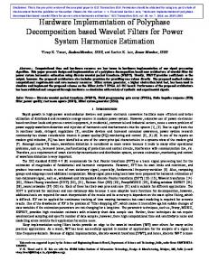
Once all components of the cooling system are assembled, installed, and commissioned with beam, transfer functions that include the beam response are measured in the accelerator complex. Transfer coaxial switches included in every medium level stochastic cooling system allow direct calibrated vector measurement of the complete gain chain via a vector network analyzer and automated measurement software. The resulting transfer function serves as the starting point for equalizer/filter design. Stochastic cooling performs most efficiently if the amplitude and phase characteristics can be tailored to optimum parameters as specified by system modeling [28]. As one might imagine, the concatenation of dozens of devices will inevitably vary from the ideal individual component measurements due to mismatches at various interconnections. Equalizers are microwave circuits that when added to the feedback system provides linearization of phase, gain slope control, and frequency response limits. The technologies utilized for fabrication include microstrip and stripline transmission lines. Resonators in the form of delay loops, transmission line stubs, hybrid circuits, coupled transmission lines, and circulators are also employed. Simple equalizers have been designed to linearize individual components such as BAW delays, or to band limit frequency response for rejection of unwanted signals. Precise band pass filters were utilized in the Debuncher cooling upgrade to minimize the sub-band overlap [29]. Figure 19 shows the pickup spectrum from Debuncher Band 2. Red trace is no beam noise
– 20 –
2011 JINST 6 T08002
Figure 19. Band 2 Debuncher momentum pickup spectrum linear scale reference level 630 microvolts, start 4.2 GHz stop 6.2 GHz. Red - no beam, green - with beam. Yellow arrows initial filter bandwidth, white arrows customized filter bandwidth. Thermal noise reduction observed is approximately a factor two.
Figure 21. Left, amplitude response; right, phase response of stacktail momentum cooling system. Blue before, red post equalization where amplitude is enhanced, phase is flattened.
bandwidth, green trace with beam before the final filters were installed. The yellow arrows indicate the 3 dB bandwidth of the original installed filters, white arrows the bandwidth of customized filters. The addition of precise frequency centered band pass filters also improved the rejection of thermal noise by approximately a factor of two. Some of the most complicated equalizers are those fabricated for the stacktail system [30]. Figure 20 shows this multi stage equalizer. Figure 21 depicts before and after beam transfer function measurements. Improvement in amplitude and phase response is evident, resulting in improved cooling performance.
– 21 –
2011 JINST 6 T08002
Figure 20. Stacktail momentum multistage equalizer covers 2–4 GHz band.
8
Summary
The development and improvement to stochastic cooling systems at Fermilab has been ongoing since the early days of commissioning in 1985. Stacking rates of antiprotons have exceeded 28x1010 per hour; almost three times the design specification. Stacks in excess of 300x1010 have been accumulated in the Accumulator ring and 600x1010 in the Recycler. In the last years of operations, the collider complex integrated more than two inverse femtobarns of luminosity annually.
Acknowledgments
References [1] S. Van Der Meer, Stochastic cooling and the accumulation of anti-protons, Rev. Mod. Phys. 57 (1985) 689. [2] F. Voelker et al., An array of 1–2 GHz electrodes for stochastic cooling, inProceedings of 1983 PAC, IEEE Conference, IEEE Trans. Nucl. Sci. 30 (1983) 2262. [3] G. Lambertson et al., Measurement of frequency response of LBL stochastic cooling arrays for TeV-1 storage rings, in Proceedings of 1985 PAC IEEE Conference, Vancouver Canada, IEEE Trans. Nucl. Sci. 32 (1985) 2168. [4] D. McGinnis, Theory and design of microwave planar electrodes for stochastic cooling of particle beams, Microw. Opt. Technol. Lett. 4 (1991) 439. [5] B. Autin et al., ACOL stochastic cooling systems, Proceedings of 1987 PAC, IEEE Conference, Washington U.S.A. (1987), pg. 1549. [6] D. McGinnis, Slotted waveguide slow-wave stochastic cooling arrays, Proceedings of 1999 PAC, IEEE Conference, New York U.S.A. (1999), pg. 1713. [7] A. Jansson et al., Experience with the 1.7 GHz Schottky pick-ups in the Tevatron, in Proceedings of 2004 European PAC, Lucerne Switzerland (2004), pg. 2777. [8] D. Pozar, Microwave engineering, third edition, John Wiley and Sons, U.S.A. (2005), pg. 489. [9] B. Leskovar, Low-noise cryogenically cooled broad-band microwave preamplifiers, in 172nd meeting of the Low Temperature Electronics Symposium, Honolulu U.S.A October 1987. [10] S. Weinreb et al., FET’s and HEMT’s at cryogenic temperature, their properties and use in low-noise amplifiers, IEEE Trans. Microwave Theor. Tech. 36 (1988) 955. [11] Miteq cryogenic amplifiers and amplifier catalog homepage, http://www.miteq.com/products/amplifiers/cryogenic-amplifiers.php. [12] R.J. Pasquinelli, Noise performance of the Debuncher stochastic cooling systems, internal document, Antiproton Source Note 661, Fermi National Accelerator Laboratory, Batavia U.S.A. (2001).
– 22 –
2011 JINST 6 T08002
The stochastic cooling system implementation initial contributions included teams at Lawrence Berkeley Lab and Argonne National Lab. Since 1985 all systems have been designed and fabricated at Fermilab with significant contributions from the Technical and Accelerator Divisions. Operations and maintenance have been stewarded by the most capable Antiproton Source and RF Departments of the Accelerator Division at Fermilab.
[13] Y. Hoshiko, K1 superconducting communication transmission, in Proceedings of the Fifth International Cryogenics Engineering conference, ICEC5, Tokyo Japan (1975), pg. 282. [14] R.J. Pasquinelli, Superconducting delay line for stochastic cooling filters, in Proceedings of 1983 PAC, IEEE Conference, Santa Fe U.S.A., IEEE Trans. Nucl. Sci. 30 (1983) 3360. [15] R.J. Pasquinelli, Superconducting notch filters for the Fermilab antiproton source, in Proceedings of the 12th International Conference on High Energy Accelerators, (1983), pg. 584. [16] Teledyne catalog for BAW devices homepage, http://www.teledynemicrowave.com/products/BAW/Baw.aspx.
[18] R.J. Pasquinelli, Fiber optic links for instrumentation, in Conference proceedings of the accelerator instrumentation workshop, October 1990, AIP Conf. Proc. 229 (1991) 180. [19] R.J. Pasquinelli, Optical notch filters for Fermilab Debuncher Betatron stochastic cooling, in Proceedings of 1989 PAC, IEEE Conference, Chicago U.S.A., IEEE Part. Accel. Conf. 1 (1989) 694. [20] Ortel Corporation 5515A/B-4515B fiber optic link data sheets. [21] Miteq fiber optic links and fiber optic link catalog homepage, http://www.miteq.com/products/fiber-optic-links/fiber-optic-links.php. [22] T. Kakuta and S. Tanaka, LCP coated optical fiber with zero thermal coefficient of transmission delay time, in Proceedings 36th International Wire and Cable Symposium, Sumitomo Electric Industries Ltd. 1, Yokohama Japan (1987), pg. 234. [23] R.J. Pasquinelli, Electro-optical technology applied to accelerator beam measurement and control, in Proceedings of 1993 PAC, IEEE Conference, Washington U.S.A. (1993), pg. 2081. [24] D. McGinnis and J. Marriner, Design of 4–8 GHz stochastic cooling equalizers for Fermilab accumulator, in Proceedings of 1991 PAC, IEEE Conference, San Francisco U.S.A., IEEE Part. Accel. Conf. 3 (1991) 1392. [25] S. Weinreb et al., NRAO, waveguide system for a very large antenna array, Microwave J. 20 (1977) 49. [26] R.J. Pasquinelli, Wide band free space transmission link utilizing a modulated infrared laser, TUA12, in Proceedings of 1999 PAC, IEEE Conference, New York U.S.A., IEEE Part. Accel. Conf. 2 (1999) 1094. [27] A.S. Gilmour Jr., Microwave tubes, Artech House Publishers, Boston U.S.A. (1986). [28] V. Lebedev, Improvements to the stacktail and Debuncher momentum cooling systems, in Proceedings of COOL 09, MOA1MCCO02, Lanzhou China (2009). [29] R.J. Pasquinelli, Debuncher momentum cooling systems signal to noise measurements, Pbar note 667, Internal Antiproton Source Document, Fermi National Accelerator Laboratory, Batavia U.S.A. (2001). [30] D. Sun et al., New equalizers for antiproton stochastic cooling at Fermilab, in Proceedings of COOL 07, THAP16, Bad Kreuznach Germany (2007).
– 23 –
2011 JINST 6 T08002
[17] R.J. Pasquinelli, Bulk Acoustic Wave (BAW) devices for stochastic cooling notch filters, IEEE Part. Accel. Conf. 3 (1991) 1395.