Sci.Int.(Lahore),28(3),2389-2393 ,2016
ISSN 1013-5316; CODEN: SINTE 8
2389
IMPLEMENTATION OF WI-FI BASED HOME AUTOMATION USING MASTER SLAVE COMMUNICATION Muhammad Ali Shafique 1, Umer Shahid 1, Ijhar Khan1, Arslan Waheed1, Muhammad Arsalan 2 and Hamza Omar3 1Department of Electrical Engineering, University of Engineering and Technology, Lahore. 2School of Electrical Engineering and Computer Science, National University of Science and Technology, Islamabad. 3University of Connecticut, storrs, CT, USA Email:
[email protected],
[email protected],
[email protected],
[email protected],
[email protected],
[email protected]
ABSTRACT: With the development of technology, automation is becoming more and more common in our daily life. Ranging from household chores to industrial scale operations, automation is becoming essential to facilitate us. The vast field of automation provides innovative solutions to control a large number of appliances. Wi-Fi based master slave communication can wirelessly control numerous appliances and embeds other features like alarm systems, voice recognition etc. The current project presents a design and prototype implementation of new home automation system that utilizes Wi-Fi technology as a network infrastructure connecting its parts. Large number of appliances can be controlled using I 2C Master-Slave communication via PC/Laptop or mobile phones application (GUI) either locally using TCP-IP protocol or remotely using internet. Keywords: Home, Automation System, Micro-controller, Window GUI, Server, I 2C.
1.0 INTRODUCTION Whenever the word “Home Automation” comes to mind, it points to some sort of wireless medium with connected controllers, which gets requests from user and can control number of appliances with relay or any switching circuitry. If we look for the needs of users and the design requirements of a home-automated system, one can suggests that an efficient home automation system should be cost-effective, energy efficient, flexible, safe to operate, secure and can control large number of appliances. In this paper, such a system and algorithm is proposed that assure to provide all these features. In the latter part, implementation of system, system elements and software used in this project will be discussed in detail. There are number of wireless technologies available these days such as Bluetooth, Wi-Fi, NFC, ZigBee and GSM. Each technology has its own pros & cons. Bluetooth and NFC have low range and bandwidth and extending their range with any circuitry is not feasible because it makes the system inefficient. ZigBee range can be increased by making a bridge with other ZigBee and also it provides I/O pins to control appliances but still this technology is not very cheap and it has local range. GSM, 3G and 4G technology has global range but these systems are affected by delays in mobile networks and one always needs mobile phone entirely dedicated for the system. Wi-Fi technology has revolutionized the world. Low cost, low power requirement and long range are key features of this technology. IoT (Internet of things) inventions has turned the automated home into the smart home. With a connections of sensors and systems, IoT connects everyday objects to a global network, which enables those objects to communicate with each other and complete their tasks, with no user input. Therefore, Wi-Fi technology has been selected as wireless medium. In order to control large number of appliances, I 2C communication has been used between servers (master) and slaves. This communication can provide thousands of I/O pins
with use of only 4 pins and range of this communication can be extended by using line drivers up to 250 m. Therefore, all communication can be carried out using single telephone wire. For energy efficient switching circuits, triac technology is used that allows switching of appliances as well as dimness of bulbs and speed of fans. This technology also avoids relay “knocking” and it can also drive heavy loads. With help of snubber circuits, it enables us to drive loads that have low power factor. The current methodology is not only cheap but also easily implementable in new and existing residents. It is also very flexible and other key features of home automation can easily be absorbed in it. The main focus of the present paper is on controlling energy saving lights and fan speed wirelessly. 2.0 SYSTEM ELEMENTS Following are the main elements of the system:
May-June
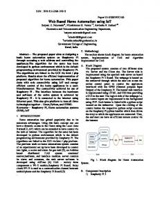
Figure 1: Block Diagram
2390
ISSN 1013-5316; CODEN: SINTE 8
Sci.Int.(Lahore),28(3),2389-2393 ,2016
Atmega328P microcontrollers will act as master as well as slave in I2C communication and also drive switching circuits. Ethernet shield that allows microcontroller to make local as well as global TCP/IP server. P82b96 which is I2C extender and carries message from master to respective slave. MOC3021 optocoupler, used to drive traic circuit. With isolation of sources on both side. Triac BT-139 that allows switching of appliances as well as dimness of bulbs and speed of fans using phase control method. Zero crossing detector for providing reference so that triac can be fired at different angles. 12V power supply to drive whole system. 2.1 Atmega328P (Arduino Uno) The Arduino Uno is a microcontroller board based on the ATmega328P. It has 14 digital input/output pins (of which 6 can be used as PWM outputs), 6 analog inputs, a 16 MHz ceramic resonator, a USB connection, a power jack, an ICSP header, and a reset button. It contains Flash memory of 32KB with 2KB SRAM and 1KB EEPROM and DC current per I/O pin is 40mA with operating voltage of 5V.[1] 2.2 Arduino Ethernet Shield The Arduino Ethernet Shield allows master microcontroller to make local network or connect to the internet. It is based on the Wiznet W5100 Ethernet chip, which provides a network (IP) capable of both TCP and UDP. It supports up to four simultaneous socket connections with speed of 10/100 MB and SPI communication with Arduino boards. It has 5V operating voltage.[2] 2.3 P82B96 The P82B96 is a bipolar IC that is used for I2C extender. It creates a non- latching, bidirectional, logic interface between 2.4 MOC3021 Table 1: I2C Bus Capabilitya normal I2C-bus and a range of other bus configurations. Bidirectional data transfer of I2C bus signal, capacitance isolation with 400 pF on Sx/Sy side and 4000 pF on Tx/Ty side are main features of this IC.[3]
Figure 2: I2C Master
Figure 3: I2C Slave
Table 1 depicts all possible configurations of this IC with varying bus capability. R1 and R2 are the resistances and C2 is the capacitor that will be connected on Master side as well as slave side as shown in Figure 2 and Figure 3 respectively. Table 1
It is a standard six terminal DIP optocoupler IC. Member of MOC302x series having 400V Phototriac Driver output and it has high isolation up to 7500V. 2.5 Triac BT-139 The TRIAC is a three terminal semiconductor device for controlling current. It is effectively a development of the SCR or thyristor, but unlike the thyristor that is only able to conduct in one direction, the TRIAC is a bidirectional device. It is used for AC switching applications because it can control the current flow over both halves of an alternating cycle.[4] Triacs are used for many electrical switching applications. Domestic light dimmers. Electric Fan speed control. Small Motor control. Control of small AC powered domestic. For switching an AC load with a microcontroller, one can simply uses either mechanical relay or solid-state relay. However, the main problem of using relay for this purpose is the low lastingness of it because relays wear off with the passage of time and start inconvenient knocking at on and off operation. Relays also draw large current to magnetize their coil during operation. After the invention of Triac devices, it became easy to switch an AC load efficiently without any noise. Triacs are not only
May-June
Sci.Int.(Lahore),28(3),2389-2393 ,2016
ISSN 1013-5316; CODEN: SINTE 8
use to switch an AC load with microcontroller but it can control the current flow over both halves of an alternating cycle facilitating user to control dimness of bulbs and speed of fan with microcontrollers. Switching of an AC load with Triac can be carried out using two methods. Pulse Skip Modulation. Phase-angle control 2.5.1 Pulse Skip Modulation One way to switch AC load with triac is Pulse Skip Modulation. In this method, one or more full cycles (sine wave) are allowed to pass through the load and few cycles are not. Though effective, it is not a good way to dim lights as it reduces frequency of the signal and increases chance for flickering. 2.5.2 Phase angle control Second way of doing it is through Phase angle control in which Triac connects the load to AC source for a portion of each cycle of input voltage. One can fire the Triac with just small pulse of few microseconds (20 µs in our case) and allow specific portion of sine AC to pass through the load but main problem is pulses from the microcontroller and firing of Triac is random and unpredictable which causes random dimness observed in bulb. One needs reference point in sine wave. Reference point can be achieved using zero crossing detectors. This is a circuit that tells the Arduino micro controller) when the sinus-wave goes through zero and therefore these zero crossing points of sine wave become reference for firing Triac circuit. Therefore, firing the Triac after calculated delay starting from the reference gives a predictable level of dimming. The difference between Phase angle control and Pulse Skip Modulation is mainly in the software. One will need a zero crossing detector so that using reference one can control a Triac. In this project, Phase Angle Control method is used.[5] 2.6 Zero Crossing Detector Figure 4 shows zero crossing circuit. 220V AC is fed in diode bride with resistor of 47K in series with diode bride. After rectification, it is led to 4N35 optocoupler that causes it‟s LED to light up for positive and negative portion of sine wave, providing zero voltage to microcontroller and when sine wave becomes zero, +5V pulse will be generated. Thus, zero crossing pulsing at 100Hz frequency is fed in microcontroller as reference.
Figure 4: Zero Crossing Detector
2391
3.0 SYSTEM IMPLEMENTATION In this section, different steps between user‟s request and command execution will be discussed. Figure 5 shows the flow diagram of the present project.
Figure 5: Flow Diagram
There are several checks to increase efficiency of the project including dynamic GUI updating and retaining previous state of GUI. 3.1 Dynamic GUI In order to make the system more user friendly, a 3d GUI is designed for the users so they can easily operate the whole system without any confusion. It is a Windows app and similar applications can also be made for smart phones and other such devices. It is a 3d GUI, which shows the current state of devices, for instance, whether it is switched on or off, when this app starts, it updates its GUI to retain the last saved „previous state‟ and whenever this app shuts down, server saves current state automatically and when application again starts, it updates the present state of itself on the by requesting server to provide string of updated condition. 3.2 User Request Presently this project offers two main features to users, which includes the switching operation of appliances i.e. to turn them on or off and the control of dimness of a fan. When the bulb is switched on, it is shown as glowing button in the app, and to switch it off, the user will press that glowing button and its state will be toggled, which is shown as a dim button in the app. Similarly, a slide bar is provided for appliances like a fan to control their dimness so that the user can easily change its speed on sliding that bar from maximum to minimum and vice versa.
May-June
2392
ISSN 1013-5316; CODEN: SINTE 8
3.3 10-Digit Code The user is actually communicating to the system through app. Since the system is a Master – Slave System, so, what the user actually sends is a 10 digit code to the master. The user sends this code through TCP/IP Protocol wirelessly over WI-FI. This code has the following format:
Sci.Int.(Lahore),28(3),2389-2393 ,2016
interrupt pin in the microcontroller. Interrupt pin is set on “RISING EDGE”. As soon as interrupt pin goes high, interrupt function is active and after calculated delay (depending on level of dimness), MOC3021 LED is lit up by microcontroller with pulse of 20 µs. MOC3021 drives BT-139 allowing that portion of sine wave.
Figure 6: 10-Digit Code Format
A single IP can be assigned to one master, so the system has the flexibility to accommodate multiple masters. As the system is based on wireless routers and access points, Router Wireless Bridging can be used to extend the maximum range of the system. Signal of one access point is received and forwarded by the second to increase the overall range of the system. Practically this IP is assigned to the Ethernet shield, which is connected to each Master. Ethernet shield is simply a communication medium that helps the app and the Master to communicate via TCP - IP Protocol. 3.4 Master Master lies at the center of the whole system. Whenever, windows app is turned on, it asks the master to send a current state of appliances. The master responds to this query and sends the current state of the appliances to the application. This is how the previous state of appliances is retained in our system. Respective updates are then received by the application and then it updates its GUI dynamically. Now, the user can toggle the switches or change the dimness and the app will communicate with the master to inform it about the current changes to take care of. A master communicates with its slaves through I2C communication. Each master can accommodate up to 110 slaves which actually corresponds to the total number of I 2C addresses (ranging from 009 to 118) available for communication. When the user requests, the master also receives a code, as mention above in the format of the code, the first three digit corresponds to the IP i.e. the respective Master. The master actually receives the remaining 7 digits of the code. Among these remaining digits, the next 3 digits correspond to the address of the slave. Hence, the master then decides that to which slave it has to communicate and then sends the remaining 4-digit code to the respective slave. 3.5 Slave The Slaves directly control appliances through Triac and Zero Detection Circuits. A slave receives the 4-digit code from its Master. Among these 4 digits, first 2 digits will decide that which pin should be altered. The remaining last 2 digits tells the state to be achieved for that pin i.e. whether it should be HIGH State or LOW State or it is some level of dimness to be achieved, the last two digits will inform the Slave about it. 3.6 Triac Circuit The pulse of train having frequency of 100Hz is fed to an
Figure 7: Triac with snubber circuit[6]
Figure 7 shows switching circuit used for this research paper. 39Ω and 0.01µF together make “snubber circuit” used to drive highly inductive loads. While 360Ω and 0.05 µF are used as “snubber circuit” for opto-coupler MOC3021. Triac BT-139 is used and depending upon driving circuit, BT-139 conduct current flow over both halves of an alternating cycle. 3.6.1 Firing angle calculation In Pakistan, AC Frequency is 50Hz-> 10ms (1/2 Cycle) to have 128 Level of Dimness (0 = Max & 128 = Min) (10000 µs – 10 µs) / 128 = 75 (Approx.) dimtime = (75 x dimming) (dimtime to fire Triac Circuit w.r.t Reference) 4.0 ANALYSIS AND EVALUATION Figure 8 will show the results of Triac circuit fired approximately 78 degrees.
Figure 8: Fired Triac
Figure 9 will show the results of zero crossing detector.
Figure 9: Zero Crossing Detector Output
May-June
Sci.Int.(Lahore),28(3),2389-2393 ,2016
ISSN 1013-5316; CODEN: SINTE 8
5.0 CONCLUSION In the nutshell, this system is flexible, reliable and secure. Single master can control switching up to 1100 appliances and also provide 220 pins for dimness purposes. This system is not confined and with help of multiple masters, number of appliances can be multiplied. Usually user is very much concern with home‟s decoration. He avoids all those services that ruins decoration. Our system is not only fascinating and attractive for the user, but also whole system is installed behind the walls. TRIAC switching circuits do their jobs in electric switch boards. 6.0 FUTURE WORKS Since it is an era of wireless communication so wireless links can be used as a replacement to I2C bus. Right now there is no sensing module is used to feel the presence of user. But we plan to use motion sensor to detect user in the room and switch lights and fans automatically according to presence of user. An important feature of any Home Automation system is its Security. We plan to develop an algorithm to use IP-cameras with our wireless infrastructure to detect any anonymous person in the house and trigger an alarm. This alarm will notify user and Police department as well so that proper safety measures can be taken.
2393
7.0 REFERENCES [1]Arduino.cc, "Arduino ArduinoBoardUno", 2016.[Online]. vailable:https://www.arduino.cc/en/Main/ArduinoBoard Uno. [Accessed: Feb- 2015]. [2] Arduino.cc, "Arduino - ArduinoEthernetShield", 2016. [Online]. Available: https://www.arduino.cc/en/Main /ArduinoEthernetShield. [Accessed: April- 2015]. [3] Nxp.com, "P82B96|NXP", 2016. [Online]. Available: http://www.nxp.com/products/.../dual-bidirectionalbus-buffer:P82B96. [Accessed: Sep- 2015]. [4] Muhammad H. Rashid, Power Electronics, Circuits, Devices and Application 3rd (316-317) 2015 [5]Instructables.com, "Arduino controlled light dimmer",2016. [Online]. Available: http://www.instructables.com/id/Arduino-controlledlight-dimmer-The-circuit/. [Accessed: May- 2015]. [6] Bristolwatch.com, "Solid State AC Relays UsingTriacs", 2016. [Online]. Available: http://www.bristol watch.com/ele/triacs2.htm. Accessed: May- 2015].
May-June