Implementing a Real-Time Cyber-Physical System Test Bed in RTDS and OPNET Bo Chen, Karen L. Butler-Purry Department of Electrical and Computer Engineering
Ana Goulart Department of Engineering Technology and Industrial Distribution
Texas A&M University College Station, TX, USA {bchen, klbutler}@tamu.edu
Texas A&M University College Station, TX, USA
[email protected]
Abstract—Numerous innovative smart grid technologies are deployed in modern power systems, making a power system a typical cyber-physical system (CPS). The increasing coupling between a physical power system and its communication network requires a smart grid simulator to run in a cyberphysical environment for cyber security research. In addition, smart grid technologies introduce numerous access points to the communication network, making cyber security a big concern in smart grid planning and operation. In this paper, a simple real time CPS test bed, implemented in RTDS and OPNET, is discussed. The setup of the test bed is introduced. Results of a case study simulated in the test bed to study the impact of cyber attacks on system transient stability are presented. The simple test bed was capable of accurately modelling a smart grid while providing user-friendly modeling experience. Index Terms—cyber-physical system, test bed, cyber security, smart grid, cyber attack, real time simulation, RTDS, OPNET
I.
INTRODUCTION
Numerous innovative smart grid (SG) technologies are increasingly deployed in modern power systems. Implementation of smart grid applications requires advanced communication technologies, making a power system a typical cyber-physical system [1]. Smart grid technologies facilitate power system planning and operations, improve system stability and reliability, and offer integration of distributed energy resources (DER) such as wind, solar and biomass [2]. Most smart grid technologies enable bidirectional data communications, hence potentially introduce cyber security issues. Numerous access points that are distributed over the smart grid become possible victims that can be compromised by potential cyber attacks [3]. The cyber security issues not only include deliberate attacks launched by corrupted employees, agents of industrial espionage, customers with hacker skills, terrorists, and other agents for benefit or political purposes, but also induced by unintentional threats such as operational error, data error, communication delay, equipment failures and natural disasters [4]. Recent research has shown that an intentional cyber attack can cause significant impact on power systems in terms of stability and economical operation [5, 6]. Therefore, cyber security of smart grid is a big security concern that is getting more and more attention along with This work was supported in part by Norman Hackerman Advanced Research Program Project 000512-0111-2009 and NSF grants EECS-1028246 and EEC-1062603.
Deepa Kundur Department of Electrical and Computer Engineering University of Toronto Toronto, ON, Canada
[email protected]
deployment of smart grid applications To address the cybersecurity issues of smart grids, research focusing on different aspects of cybersecurity has been conducted. A framework was proposed in [7] for cyber attack impact analysis. Potential vulnerabilities were identified in [8, 9]. Several cyber attacks and their impact on smart grids were studied in [6, 10], and corresponding mitigation strategies were investigated in [11, 12]. However, current efforts to address cyber security issues are constrained by the availability of a cyber-physical test bed. To achieve cyber security resiliency, a test bed that can simulate realistic cyberphysical environments is needed to evaluate the cyber attacks and verify the proposed mitigation strategies [13]. Several CPS test beds have been developed in [14-18]. In [14], a test bed was developed for SCADA cyber security. PowerWorld was used for simulating physical power systems. A real time immersive network simulation environment (RINSE) was integrated with PowerWorld to emulate realistic networks as well as cyber attacks and defenses. In [15], a hybrid test bed was developed by combining hardware (computers, routers, switches, firewalls, etc.) and software (OPNET). The system-in-the-loop (SITL) feature of OPNET was used to bridge hardware and software, making the test bed reconfigurable. To detect the cyber attacks on SCADA, authors in [16] developed a test bed with PowerWorld and OPNET. However, these test beds cannot run in real time or perform hardware-in-the-loop (HIL) simulation. A real time test bed was developed in [17] with the real time digital simulator (RTDS) and network analyzer, which can simulate denial of service (DoS) attacks. Authors in [18] developed a cyber-physical security test bed using RTDS, DIgSILENT and the internet-scale event and attack generation environment (ISEAGE). Three types of cyber attacks were performed and the impact was evaluated. In this paper, a real time cyber-physical test bed, developed in RTDS and OPNET, is discussed. The HIL and SITL capacities of the test bed allow implementation of a combination of hardware, software, emulators and other intelligent electronic devices (IEDs). The remainder of this paper is organized as follows. Section II reviews cyber security issues and requirements for a CPS test bed. Section III introduces the proposed real time cyber-physical test bed. A case study is presented in section IV, and the impact of man-in-the-middle attack on power
system is discussed. Finally, conclusions and future work are discussed in section V. II.
TEST BED FOR CYBER-PHYSICAL SMART GRID
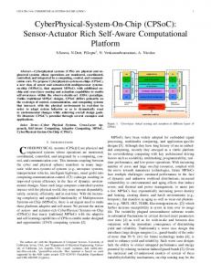
Smart grid is a typical cyber-physical system due to the tight coupling between information and communication technologies (ICT) and physical power systems. The cyberphysical security of smart grid should be investigated to guarantee the grid’s resilience. A CPS test bed is needed to conduct the cyber security research. A. Cyber-Physical Security for the Smart Grid Cyber security of smart grid is becoming increasingly important due to the adoption of smart grid technologies. U. S. Department of Energy (DOE) has identified cyber security as a primary requirement for enhancing the security and reliability of the next generation grid [19]. The widely deployed smart grid technologies, such as wide area monitoring system (WAMS), advanced metering infrastructure (AMI), demand response (DR) and microgrid, are implemented based on bi-directional data communication [20]. Measurement data, control commands, electricity price signals and other types of data are transmitted between control centers and end users through an interconnected communication network. On one hand, these technologies greatly facilitate smart grid in terms of reliability, stability and economic operation. On the other hand, cyber security issues are introduced inevitably, due to numerous accessing points that are exposed to potential hazards. An attacker with knowledge of communication, networking and power system can easily launch cyber attacks. B. Need for a Cyber-Physical Test Bed Traditional software can only simulate or emulate communication networks (e.g. OPNET, NS2, OMNET) or physical power systems (e.g. RTDS, DSATools, PSS/E, PowerWorld). These software cannot provide a realistic cyberphysical environment to study the characteristics of cyberphysical system. It can be expected that any attacks on either the cyber part or the physical part will definitely impact the other part. For example, a denial of service (DoS) attack can flood a communication node, induce network delay, slow network performance, or even make the network unavailable to perform intended functionalities. If a voltage regulator is compromised by DoS attacks, its controller will act abnormally and cause degradation of performance [21]. On the other hand, changes of a physical system will influence network performance since the physical system determines the data transmitted through the network and energizes network devices such as data servers, routers, switches, transmitters and antennas. Therefore, to investigate the cyber security of smart grid, a CPS test bed is needed to precisely model a cyber-physical smart grid. C. CPS Test Bed Capabilities and Applications A CPS test bed needs certain capabilities to support cyber security research. Figure 1 shows four critical capabilities of a CPS test bed to implement the test bed applications that are specified in [18].
Figure 1. CPS test bed capabilities and applications
1) Cyber-physical security simulation: This is a basic capability of the proposed test bed. A CPS test bed is supposed to not only simulate a power system and its networking system simultaneously, but also simulate most types of cyber attacks and physical contingencies that are normally encountered in the real world. This enables researchers to do impact analysis and vulnerability evaluation. 2) Data virtualization: A CPS test bed should be able to derive the interested data easily. Data virtualization allows researchers to get an idea of what is going on at each step during simulation. This is important since it is the only way that the impact of cyber attacks can be used to observe, or evaluate the performance of mitigation strategies. 3) Interoperability[18]: To evaluate the performance of intelligent electronic devices (IED) in the context of cyberphysical smart grids, a CPS test bed should be able to connect to external hardware to perform the hardware-in-the-loop (HIL) simulation and system-in-the-loop (SITL) simulation. Also, the test bed should be able to run in real time to provide realistic data to drive IEDs. 4) Scalability: Scalability refers to the ability of configuring topology for both a cyber system and a physical system. This is useful when researchers try to study the impact of cyber attacks on different power systems with same communication network, or the same power system with different types of communication networks. Four main test bed applications shown in Figure 1 are introduced below. 1) Impact analysis[18]: The proposed test bed should be able to analyze the impact of potential cyber attacks on power system in terms of reliability, stability and economic operation. The impact analysis helps researchers have a clear sense of potential hazards when the system is subjected to cyber attacks and physical hazards. 2) Vulnerability evaluation[18]: A security vulnerability is a weakness that can be utilized by potential attackers to compromise the integrity, availability, or confidentiality of the system [7]. Smart grid incorporates numerous hardware and software with potential vulnerabilities in the protocols and communication media. Vulnerability evaluation is to detect the deficient that exists in a communication network. The test bed should allow researchers to perform different strategies to evaluate possible vulnerabilities.
3) Mitigation Evaluation[18]: Researchers need to test the proposed mitigation strategies. A CPS test bed should be able to implement the proposed mitigation strategies and provide data virtualization to generate a verification report. For example, to mitigate a DoS attack, researchers may propose a reconfiguration method to isolate or limit the bandwidth of the compromised channel. The test bed is supposed to implement the proposed mitigation method by configuring the network accordingly and providing data visualization such as real time traffic monitoring. 4) Training and education[18]: A CPS test bed should not only virtualize the cyber data and the physical data, but also be able to receive the control commands from system operators to mitigate the potential threats. In addition, userfriendly modeling experience and data virtualization will make a test bed suitable for educational purposes. III.
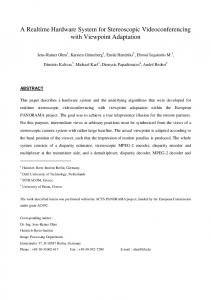
PROPOSED REAL TIME CYBER-PHYSICAL TEST BED
Physical System Modeler
Cyber System Modeler
Power System Controllers
Control Center & Substations
(implemented in RTDS)
(implemented in third party simulator)
Control commandsMeasurement data
Power System (implemented in RTDS)
Measurement dataControl commands
Physical IEDs
Data Exchange Socket
Control/dispatch commentsPackets
Communication Network (implemented in OPNET) Packets
Packets
Physical Networking Devices
Figure 2. Architecture of the proposed cyber-physical system test bed
should be done in real time. The blocks in Figure 2 are introduced below.
1) Physical System Modeler: Physical system modeler comprises a power system modeler and corresponding controllers, as well as physical IEDs. The power system modeler (RTDS) includes all the modeling components that represent a physical system, such as generators, transformers, lines and loads. The controllers (e.g. exciter, governor) collect the measurement data from the power system model and send control commands. Similarly, a physical IED (e.g. A. Test Bed Elements The real time digital simulator (RTDS) is used to simulate protective relay, PMU) can also exchange needed data with a power system and perform analogue/digital input/output the power system model and the controller. The data can (I/O). The OPNET Modeler is used to simulate either be exchanged within the physical system modeler, or communication networks, generate traffic, and launch cyber be exchanged through the cyber system modeler, depending attacks. The National Instruments LabVIEW PXI platform [22] on whether a controller or a control IED is connected to the with field-programmable gate array (FPGA) bridges OPNET communication network. RTDS can easily model a power and RTDS while providing supplemental data virtualization. system and its controllers using its user interface software 1) RTDS: Real time digital simulator (RTDS) is RSCAD. The GTNET card, as well as the GT-AI/O card and specifically designed for simulating power systems and GT-DI/O card, enables RTDS to communicate with the cyber testing physical IEDs with high accuracy [23]. Various I/O system modeler through ethernet or analogue/digital I/O ports. 2) Cyber System Modeler: Cyber system modeler cards with numerous analogue and digital channels enable the HIL feature to be implemented easily. Furthermore, the (OPNET) can interact with physical system modeler by GTNET card supports various protocols (GSE, SV, DNP) simulating a reconfigurable communication network. The control center and the substation networks can be modeled in based on the data format defined in IEC 61850 standards. 2) OPNET Modeler: The OPNET modeler can simulate a the cyber system modeler. Physical networking devices complicated networking environment that supports various enable the interaction between a virtual communication industrial protocols and technologies [24]. The system-in-the- network and a physical communication network. Smart grid loop (SITL) feature enables researchers to evaluate the applications in control centers and substations are performance of a network that is comprised of virtual implemented in third party software. The SITL feature network and physical networking devices in real time. Rich enables OPNET software to interact with external network visualization and user-friendly operability make models interfaces (e.g. PC, switch, router, server). 3) Data Exchange Socket: Data exchange socket enables developed in OPNET easy to understand, thus suitable for data to be exchanged between the cyber system modeler and training and education. 3) LabVIEW Real-Time Module: To bridge RTDS and the physical system modeler. The analogue and the digital OPNET in real time, the LabVIEW PXI platform acts as a signals generated by GT-AI/O and GT-DI/O cards are converted into packets that transferable in the cyber system mediator in the proposed test bed. modeler. On the other hand, the packets will be parsed and B. Test Bed Architecture converted to analogue or digital signals before being used by The architecture of the CPS test bed that is comprised of the physical system modeler. In addition, the data exchange the elements introduced above is shown in Figure 2. The data socket should be able to run in real time while introducing exchange between cyber and physical is time critical and minimum communication delay. Since there are no off-the-shelf products that are specifically for cyber-physical simulation, the so-called “cosimulation technology” is utilized for the work reported in this paper. A power system simulator and a network simulator were synchronized to run simultaneously and the data was exchanged between them.
C. Setup of the Proposed CPS Test Bed The setup of the proposed test bed is described in Figure 3. Three PCs are used for hosting RTDS, NI PXI and OPNET, respectively. RSCAD is used for modeling the physical power system and its controllers. In Figure 3, an 11 bus system is shown and will be used in later case study. RTDS can run at a time step of 50 microseconds while showing the required system response on the host PC. With a GTNET card, RTDS sends out the measurement values (e.g. bus voltage, line current, switch status) based on IEC 61850-9 Sampled Values, which is a commonly used data format in substations. Therefore, the GTNET card can be seen as a merging unit in a substation. The sampling rate of GTNET card is 80 samples per cycle, which is 4800 samples per second. The high sampling frequency ensures the accurate and fast data communication. The data packets that sent from GTNET will be captured and pushed through a virtual communication network developed in OPNET. The packet capture capability is enabled by the open source software WinPcap [25]. The virtual network that is shown in Figure 3 is a substation network using a ring topology to improve communication resiliency. The SITL feature of OPNET provides two or more Ethernet access ports (i.e. RJ45), which allow GTNET to connect to one network adapter loaded on the OPNET host PC, and allow NI PXI to connect to another network adapter. The packets will go through the virtual network and experience a network delay that is determined by the network traffic. To send packets back to RTDS, NI PXI and FPGA can perform packet parsing and analogue/digital I/O in real time. The deterministic and extremely fast execution minimizes the unnecessary delay that may be introduced into the simulation. The host PC can continuously communicate with PXI and FPGA, making it easy to virtualize the data and to adjust the parameters during the simulation.
Gen1
2
6 7
1
10
8
11
5
9
Gen2
4
3
Figure 3. Setup of the proposed cyber-physical test bed
To illustrate how to model a cyber-physical smart grid in the test bed, Figure 4 shows a substation automation system (SAS) modeled in the proposed test bed. A typical SAS is normally structured in three levels: Station level, bay level and process level [26]. 1) Process Level: Includes primary equipment such as potential transformer (PT), current transformer (CT), merging units (MU). Some other elements in the process level that are not shown in Figure 4 include remote I/O, actuators, etc. In the proposed test bed, the process level is implemented in RTDS. The component library of RSCAD enables researchers to develop a power system and the primary equipment easily. GTNET card can act as a merging unit.
Figure 4. A substation automation system modeled in the proposed test bed
CASE STUDY
A. Test System To evaluate the proposed test bed, an 11 bus test system was modeled in RTDS. The parameters of the test system are available in [5]. The single line diagram is shown in Figure 3. A static var compensator (SVC) was connected to bus 11. The performance of SVC under both normal condition and contingency condition can be found in [5]. Figure 3 also shows the communication network of a single substation. Future work will develop a communication network that includes a control center and multiple substations. B. Man-In-The-Middle Attack In the case study, a man-in-the-middle (MITM) attack was assumed to be launched on the control IED of SVC. As shown in Figure 5, to launch a MITM attack, the attacker or the virus will disconnect the connection between the MU in process level and the control IED in bay level, then make two independent connections to the MU and the control IED, respectively. The attacker can act as a mediator between the MU and the control IED by pretending the data source or the data target, hence making the MU and the control IED believe that they are still communicating with each other directly. After intercepting the connections, the attacker can get control of the message by delaying or modifying the payload of the packets [27]. In this study, the attacker recorded the measurement values derived from the MU, and injected them to the control IED. Thus the control IED continued to receive the values that were replayed repeatedly by the attacker. C. Impact of MITM Attack The MITM attack was assumed to be launched under normal condition. A 3-phase bolted fault happened at bus 7 at time 1.0 s, and cleared after 67 ms (4 cycles) by opening line 3-7. The attacker kept injecting the measurement values that recorded under normal condition to the control IED of SVC.
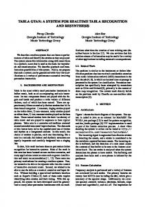
Two scenarios, with and without MITM attack, were considered. Figure 6 shows the 3-phase voltage at bus 11 received by the SVC controller for both scenarios. The upper subplot indicates that the control IED under MITM attack always received normal condition signals, even when a fault happened. Therefore, the SVC controller cannot see the change of voltage. The actual 3-phase bus voltage is shown in the bottom subplot, in which the voltage dipping and fluctuation cannot be captured by the compromised controller. The reactive power outputs of SVC in both scenarios are shown in Figure 7. For both scenarios, SVC fixed its output around 100 MVar under normal condition. When the fault happened, the control IED under MITM attack cannot respond to the voltage drop. Whereas in the scenario without MITM attack, SVC can provide up to 500 MVar reactive power when the bus voltage dipped down. The RMS voltages at bus 11 for both scenarios are shown in Figure 8. Compared to the bus voltage without MITM attack, the bus voltage deteriorated due to lack of sufficient voltage support from SVC. In conclusion, the performance of SVC was deteriorated by the MITM attack. The SVC cannot provide enough reactive power. The bus voltage cannot be regulated as expected. The test bed can provide cyber-physical modeling capability to perform impact analysis.
Received Voltage (KV)
IV.
Figure 5. Man-In-The-Middle attack
Actual Voltage (KV)
2) Bay Level: Includes secondary equipment such as protective relays and control intellegent electrical devices (IEDs). There can be multiple bay levels depending on the usage of IEDs, such as circuit breakers, transformers, and flexible AC transmission system (FACTS). Some IEDs may need information from other IEDs. The needed data will directly come from the corresponding MUs, or from the station level. The bay level is also implemented in RTDS. NI PXI is used for bridging RTDS and OPNET by performing data conversion. In addition, NI PXI can also implement a complex bay level IED. 3) Station Level: Includes human machine interface (HMI) that provides an overview across the whole station, remote terminal unit (RTU), global positioning system (GPS) receiver etc. The station level is located in the control room. The station level is implemented in OPNET. These three levels are interconnected through a substation communication network. The tree topology or/and the ring topology will be used in the substation network to provide redundancy networking capacity. The SAS of a substation can also communicate with other substations and the grid control center through the wide area network (WAN) or Ethernet.
400 200 0 -200
200 0 -200 -400 0
0.5
1
1.5
2 2.5 3 Time (second)
3.5
4
4.5
Figure 6. 3-phase voltage data received by SVC controller (top) and actual 3-phase voltage at bus 11 (bottom)
[6]
Reactive Power Output of SVC (MVar)
600
Without MITM Attack With MITM Attack
500
[7]
400 300
[8] 200
[9]
100 0 -100 0
[10] 0.5
1
1.5
2 2.5 3 Time (second)
3.5
4
4.5
5
[11]
Figure 7. Reactive power output of SVC 1.1
Without MITM Attack With MITM Attack
RMS Voltage at Bus 11 (p.u.)
1.05 1 0.95
[13]
0.9
[14]
0.85 0.8
[15]
0.75 0.7 0
0.5
1
1.5
2
2.5 3 Time (second)
3.5
4
4.5
Figure 8. RMS voltage at bus 11
V.
REFERENCES
[2] [3] [4] [5]
[16]
CONCLUSIONS AND FUTURE WORK
This paper introduced a simple cyber-physical system test bed implemented in RTDS and OPNET. The capabilities of the proposed test bed were discussed, and the elements and the architecture of the test bed were introduced. The mechanism of data generating and exchanging was elaborated. To analyze the impact of cyber attacks on power system, a case study was conducted. The MITM attack was launched and its impact on system transient stability was studied. The proposed simple test bed can provide realistic cyber-physical testing environment in real time. Future work includes studying the impact of cyber attacks on various power system models simulated in the test bed and development of a framework to identify cyber physical system vulnerabilities based on the results. [1]
[12]
M. Govindarasu, A. Hahn, and P. Sauer, "Cyber-Physical Systems Security for Smart Grid," Power Systems Engineering Research CenterMay 2012. A. Ipakchi and F. Albuyeh, "Grid of the future," IEEE Power and Energy Magazine, vol. 7, pp. 52-62, 2009. M. Yilin, T. H. J. Kim, K. Brancik, D. Dickinson, L. Heejo, A. Perrig, et al., "Cyber Physical Security of a Smart Grid Infrastructure," Proceedings of the IEEE, vol. 100, pp. 195-209, 2012. NRECA, "Guide to Developing a Cyber Security and Risk Mitigation Plan," 2011. B. Chen, S. Mashayekh, K. L. Butler-Purry, and D. Kundur, "Impact of Cyber Attacks on Transient Stability of Smart Grids with Voltage Support Devices," in Proc. 2013 IEEE/PES General Meeting, Vancouver, Canada, 2013.
[17]
[18] [19] [20] [21]
[22] [23] [24] [25] [26] [27]
X. Le, M. Yilin, and B. Sinopoli, "Integrity Data Attacks in Power Market Operations," IEEE Transactions on Smart Grid, vol. 2, pp. 659666, 2011. D. Kundur, F. Xianyong, L. Shan, T. Zourntos, and K. L. Butler-Purry, "Towards a Framework for Cyber Attack Impact Analysis of the Electric Smart Grid," in Proc. 1st IEEE International Conference on Smart Grid Communications, Gaithersburg, pp. 244-249. T. Chee-Wooi, L. Chen-Ching, and G. Manimaran, "Vulnerability Assessment of Cybersecurity for SCADA Systems," IEEE Transactions on Power Systems, vol. 23, pp. 1836-1846, 2008. S. Sridhar, A. Hahn, and M. Govindarasu, "Cyber Physical System Security for the Electric Power Grid," Proceedings of the IEEE, vol. 100, pp. 210-224, 2012. O. Kosut, J. Liyan, R. J. Thomas, and T. Lang, "Malicious Data Attacks on the Smart Grid," IEEE Transactions on Smart Grid, vol. 2, pp. 645-658, 2011. T. T. Kim and H. V. Poor, "Strategic Protection Against Data Injection Attacks on Power Grids," IEEE Transactions on Smart Grid, vol. 2, pp. 326-333, 2011. S. Zonouz, K. M. Rogers, R. Berthier, R. B. Bobba, W. H. Sanders, and T. J. Overbye, "SCPSE: Security-Oriented Cyber-Physical State Estimation for Power Grid Critical Infrastructures," IEEE Transactions on Smart Grid, vol. 3, pp. 1790-1799, 2012. A. Hahn and M. Govindarasu, "Cyber Attack Exposure Evaluation Framework for the Smart Grid," IEEE Transactions on Smart Grid, vol. 2, pp. 835-843, 2011. C. M. Davis, J. E. Tate, H. Okhravi, C. Grier, T. J. Overbye, and D. Nicol, "SCADA Cyber Security Testbed Development," in Proc. 38th North American Power Symposium, 2006, pp. 483-488. B. van Leeuwen, V. Urias, J. Eldridge, C. Villamarin, and R. Olsberg, "Cyber security analysis testbed: Combining real, emulation, and simulation," in Proc. 2010 IEEE International Carnahan Conference on Security Technology (ICCST), 2010, pp. 121-126. M. Mallouhi, Y. Al-Nashif, D. Cox, T. Chadaga, and S. Hariri, "A testbed for analyzing security of SCADA control systems (TASSCS)," in Proc. 2011 IEEE PES Innovative Smart Grid Technologies (ISGT), 2011, pp. 1-7. U. Adhikari, T. H. Morris, N. Dahal, S. Pan, R. L. King, N. H. Younan, et al., "Development of power system test bed for data mining of synchrophasors data, cyber-attack and relay testing in RTDS," in Proc. 2012 IEEE Power and Energy Society General Meeting, 2012, pp. 1-7. A. Hahn, A. Ashok, S. Sridhar, and M. Govindarasu, "Cyber-Physical Security Testbeds: Architecture, Application, and Evaluation for Smart Grid," IEEE Trans. on Smart Grid, vol. 4, pp. 847-855, 2013. NETL, "A systems view of the modern grid," U.S. Department of Energy (DOE) National Energy Technology Laboratory (NETL)2007. NIST, "NISTIR 7628: Guidelines for Smart Grid Cyber Security," National Institute for Standards and Technology (NIST)2010. B. Chen, K. L. Butler-Purry, S. Nuthalapati, and D. Kundur, "Network Delay Caused by Cyber Attacks on SVC and its Impact on Transient Stability of Smart Grids," in Proc. 2014 IEEE Power and Energy Society General Meeting (PES), 2014, pp. 1-5. NI PXI website. Available: http://www.ni.com/pxi/ RTDS Technologies. Available: http://www.rtds.com/ Network Simulation (OPNET Modeler Suite). Available: http://www.riverbed.com/products-solutions/products/networkplanning-simulation/Network-Simulation.html WinPcap official website. Available: http://www.winpcap.org/ IEC. IEC 61850-5 communication networks and systems in substations – Part 5: communication requirements for functions and device models. Available: http://www.iec.ch E. Ciancamerla, M. Minichino, and S. Palmieri, "Modeling cyber attacks on a critical infrastructure scenario," in Proc. 2013 Fourth International Conference on Information, Intelligence, Systems and Applications (IISA), 2013, pp. 1-6.