Implementing an Improved Stereoscopic Camera Model Barbara Froner, Nick Holliman, Department of Computer Science, University of Durham, United Kingdom.
[email protected],
[email protected]
Abstract The usable perceived depth range of all stereoscopic 3D displays is limited by human factors considerations to a bounded range around the plane of the display. To account for this our Three Region stereoscopic camera model is able to control the depth mapping from scene to display while allowing a defined region of interest in scene depth to have an improved perceived depth representation compared to other regions of the scene. This can be categorized as a focus+context algorithm that manipulates stereoscopic depth representation along the viewing axis of the camera. We present a new implementation of the Three Region stereoscopic camera model as a Utility plug-in for the popular modelling and rendering package 3ds max. We describe our user interface, designed to incorporate stereoscopic image generation into the user’s natural work flow. The implementation required us to overcome a number of technical challenges including; accurately measuring scene depth range, simulating asymmetric camera frustum in a system only supporting symmetric frustum, merging multiple renderings and managing anti-aliasing in layered images. We conclude from our implementation that it is possible to incorporate high quality stereoscopic camera models into standard graphics packages. Categories and Subject Descriptors (according to ACM CCS): I.3.3 [Computer Graphics]: Picture/Image Generation I.3.4 [Computer Graphics]: Graphics Utilities I.3.7 [Computer Graphics]: Three Dimensional Graphics and Realism
1. Introduction The properties of stereoscopic displays frequently present a challenge for content creators with many scenes containing a larger depth range than a 3D display can present to the viewer. For example, trials using a high quality desktop autostereoscopic 3D display by Sharp Corporation [JLHE01] demonstrated that the range of fusable perceived depth range could be as little as [−50mm, +60mm] in-front and behind the display surface. These limits are generally understood to result from a combination of factors including the display’s level of inter-channel crosstalk [YS90], the quality of the stereoscopic images [Hol] and the ability of the viewer to fuse screen disparity into a single image. Recent guidelines published by the 3D Consortium [3D ] indicate that it is particularly important to control preceived depth range if children are the target audience for the final images. Content creators therefore need to control how scene depth is captured in stereoscopic images. The problem can
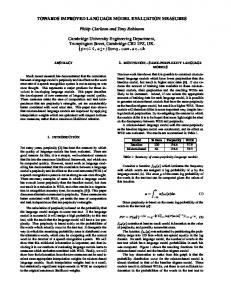
Scene depth range
Virtual display Physical display
(a)
Perceived depth range
Figure 1: Single Region stereoscopic image capture maps a range of scene depth to a range of perceived display depth.
B. Froner & N.S. Holliman / Implementing an Improved Stereoscopic Camera Model
Scene depth range
3D display plane
L
e NR
Region of interest
p
R
FR
(1) gpd = z / ( (e/d) – 1 )
d
p, perceived depth z, viewing distance e, eye separation d, screen disparity
z
L
e Perceived depth range
d R
(2) gpd = z / ( (e/d) + 1 )
p
(b)
Figure 2: Three Region stereoscopic camera control can vary depth mapping, for example a defined region of interest (ROI) may be given the best stereo depth representation.
Figure 3: Geometric perceived depth for positive, (1), and negative, (2), screen disparity.
cal challenges overcome to create a new implementation of the algorithm as a plug-in for the 3ds max software package. be considered a mapping of scene depth onto the available range of perceived depth on the target stereoscopic display as shown in figure 1. A recent Single Region solution [JLHE01] was able to guarantee this mapping had specific properties, for example that the perceived depth would not exceed predefined ranges and that the perceived depth remains constant when there is tracked head movement. Experience generating images using this method was positive, it allowed novice 3D display users to have repeatable control over the depth mapping from scene to displayed image. As a result stereoscopic content production using computer graphics and digital photography no longer required repeated trial and error to produce an image with defined stereoscopic depth properties. However, Single Region solutions to stereoscopic image capture have drawbacks because they map a single range of scene depth onto the target display depth range as a whole. This has the consequence that a region of interest in scene depth cannot be guaranteed to have any particular representation in perceived depth in the final displayed image. We previously introduced an improved stereoscopic camera model [Hol04] allowing the content creator to define different mappings from real scene depth to perceived display depth for three different ranges; a region of interest (ROI) in the scene, a near region (NR) and a far region (FR) in the scene. As shown in figure 2, all three regions can be mapped to a different proportion of the available perceived depth range on the target 3D display. The result is that the image creator can choose to give better stereoscopic representation to the ROI compared to the near and far regions. In this paper we review the development of the Three Region algorithm and then describe the design and key techni-
2. The Geometry of Perceived Depth Depth perception in planar stereoscopic images has been widely studied and the geometry of stereoscopic depth perception is well known [Hel67,WDK93,Hol,HR03]. The image disparity captured when a stereo image pair is created becomes physical screen disparity when the stereo pair is displayed on an electronic 3D display. The screen disparity is detected by the retina and interpreted by the brain as a perceived depth in-front or behind the screen plane, as shown in figure 3. While a viewer’s actual perception of depth resulting from a given screen disparity is important we adopt the common approximation of considering geometric perceived depth gpd [WDK93, JLHE01, Hol]. This is calculated, as shown in figure 3, from the value of screen disparity the viewer perceives. 3. A Three Region Depth Mapping Algorithm We summarize the derivation of an improved stereoscopic camera model introduced in [Hol04] that uses Three Region depth mapping to overcome the limitations of previous single region depth mapping algorithms. This is a parallel camera axis model and as we describe the method for symmetric camera frustum we must also consider appropriate image cropping calculations so that infinity is not represented at the screen plane. An alternative version of the algorithm for asymmetric camera frustum, suitable for use with real time graphics packages such as OpenGL is presented in [Hol05]. We consider two distinct geometries; the geometry defining the relationship between the viewer and the display and c The Eurographics Association 2005. °
B. Froner & N.S. Holliman / Implementing an Improved Stereoscopic Camera Model
f
z N
F
f’
z’
n
N’
F’
n’ w’
w dN dn
a’
d’n t’m
df dF
e
d’f
a’ t’
NR viewer eye positions perceived points at region limits. disparity of points at region limits. display width limits.
ROI
FR
Total gpd range Physical display plane
Figure 4: The display viewing geometry showing total gpd range and the split into near, ROI and far regions.
the geometry of the scene and the camera. The Three Region algorithm maps the defined regions, NR, ROI and FR in scene depth onto corresponding defined ranges of gpd. This mapping is required to meet the constraint that points on the region boundaries are projected to coincident positions, and hence depth, in the image pair whichever region they are considered to belong to. The algorithm therefore implements perspective projection as a piecewise continuous function of scene depth and uses a different perspective projection (different stereo cameras) to capture each of the three regions.
camera positions monoscopic camera position disparity of points at region limits. display width.
NR’
ROI’
FR’
Virtual display plane.
Figure 5: The scene geometry showing defined near, ROI and far regions of scene depth and the monoscopic camera position.
ROI [n0 , f 0 ] and far [ f 0 , F 0 ] regions by the planes at distances n0 and f 0 from the viewer. These regions are to be mapped to the defined ranges of gpd on the target display. In single region methods a single stereo camera separation a0 is calculated for the camera to take the left and right images. In the Three Region approach we need to find three camera separations one each for the NR, ROI and FR regions. The calculations to determine these mappings are summarized in the following three sections.
3.1. Display Geometry
3.3. Region of Interest Mapping
The geometry of display viewing is illustrated in figure 4. The viewer’s half eye separation is given by e, the screen plane is at distance z from the viewer and the half screen width is w. The total gpd range is between the planes at distances N and F from the viewer and is divided into a near range, NR [N, n], a region of interest range, ROI [n, f ], and a far range, FR [ f , F], by planes defined at distances n and f from the viewer. The half screen disparities of points lying on the display viewing centre line for the planes at distances N, n, f and F are given by dN , dn , d f and dF respectively. Note, in each case the geometry for just one view is shown in our diagrams for clarity.
The aim is to map the region of depth in the scene defined as the ROI onto the matching region of gpd identified for the target display. The display is represented in the scene by a virtual display plane. This allows us to consider the mapping of scene depth onto disparities in the virtual display plane separately from the physical disparities on the target display. We summarise key equations from the derivation presented in [Hol04] and follow the terminology defined there. We first find an expression for z0 , the distance to the virtual screen plane: z0 =
f 0 n0 + f 0 n0 r f 0 + n0 r
(1)
3.2. Scene Geometry The geometry of the scene and camera is illustrated in figure 5. We assume that the image creator has positioned a monoscopic camera that frames the required view of the scene. The total depth range in the scene we are asked to capture is [N 0 , F 0 ] and this is divided into the near [N 0 , n0 ], c The Eurographics Association 2005. °
where r is a ratio related to the maximum crossed and uncrossed disparities and is equal for disparities on both the virtual and physical display planes. We can then derive the virtual display width at z0 and from this the camera separation, a0 , required to map the defined
B. Froner & N.S. Holliman / Implementing an Improved Stereoscopic Camera Model
range of scene depth to the defined range of gpd for the ROI: sdn n0 (2) z0 − n0 Here s is a scaling factor that maps disparities from the virtual display plane in the scene to the physical display. We now have almost all the information needed to calculate the left and right camera positions and generate the left and right partial images for the ROI region with the exception of the new field of view: ¶ µ 0 w + a0 t 0 = 2atan (3) z0 a0 =
The above is the field of view for a camera with a symmetric frustum and hence when the image is generated we must clip a proportion of pixels from the left and right edges of the left and right partial images respectively. This ensures that points projecting zero disparity onto the virtual screen plane will also have zero disparity when displayed on the physical screen plane. The proportion of pixels to crop from the left of the left image and the right of the right image is given by: c0 =
a0 w0 + a 0
(4)
We can now generate, for both left and right views, the partial images that capture the ROI in the scene and represent it within the given range of gpd on the final display. When generating these images the ROI region boundaries are used as clipping planes so that only the relevant geometry need be processed. The process so far has been equivalent to a Single Region mapping and we now consider how to calculate camera parameters and partial images for the NR and FR regions of the scene. 3.4. Near Region Mapping For the near region (NR) we map the scene depth in [N 0 , n0 ] to the gpd [N, n] using the same image plane at z0 used for the ROI mapping, as shown in figure 6. We need to ensure that points on the plane at n0 map to the same position in the final image whether they are mapped by the ROI step or the NR step. We can consider this to be a constraint that the field width of the ROI camera and the NR camera be the same in the plane at distance n0 from the camera location. This will result in a piecewise continuous representation of stereoscopic depth which meets at region boundaries.
N’
F’
f’
z’ n’ o’’
w’’ d’n
a’’
d’’N d’’n
a’
NR camera positions ROI camera positions monoscopic camera position disparity of points at region limits field widths
o’’ NR’
ROI’
FR’
Figure 6: The scene geometry showing the variables related to the near region.
The offset adjustment is the difference between the disparity in the virtual display of a point on the shared plane n0 plane projected by the a0 and a00 cameras, and is given by: o00 = dn0 − dn00
(6)
Using the above to determine w00 the symmetric field of view for the left and right NR cameras, t 00 , is: µ 00 ¶ w t 00 = 2atan (7) z0 Again as we are using symmetric camera frustum we have to crop a proportion of pixels, c00 , from the resulting images where: c00 =
a00 − o00 00 o00 − a00 00 00 00 , o < a or c = , o >= a00 (8) w00 w00
Note that if o00 < a00 then we crop pixels from the left of the left image and the right of the right image while if o00 >= a00 then we crop pixels from the right of the left image and left of the right image. We now have the camera parameters and image adjustments we need to render the NR partial images for the left and right views. Again during rendering we can clip the scene so that only geometry relevant to the NR is processed.
For the NR mapping we calculate a new half camera separation a00 , a symmetric field of view, t 00 , and the associated image cropping, c00 . Additionally we need an offset adjustment o00 that we use to shift the NR disparity range to be continuous with the disparity range for the ROI region.
3.5. Far Region Mapping
Via similar geometric reasoning to the ROI region we can find a00 for the NR to be: s(d − dn ) a00 = ³ 0 0 ´N ³ 0 0 ´ (5) z −N − z −n N0 n0
For the far region (FR) we need to map the scene depth in [ f 0 , F 0 ] to the gpd range [ f , F] rendering onto the same image plane at z0 used for the ROI mapping, as shown in figure 7. As for the NR mapping we need to ensure that points on the plane at f 0 map to the same position in the final image c The Eurographics Association 2005. °
B. Froner & N.S. Holliman / Implementing an Improved Stereoscopic Camera Model
N’
F’
f’
z’ n’ o’’’
w’’’ d’’’F
d’’’f a’’’
d’f
a’
NR camera positions ROI camera positions monoscopic camera position disparity of points at region limits field width limits
NR’
ROI’
FR’
Figure 8: To the right of the image is the options panel for the inThreeD plug-in. Figure 7: The scene geometry showing the parameters related to the far region. 4. Plug-in Design and Implementation whether they are mapped by the ROI step or the FR step. We can consider this as a constraint that the FR and ROI cameras have the same field width in the plane f 0 . We first need to calculate a new camera separation a000 that will map [ f 0 , F 0 ] to [ f , F]: a000 = ³
s(dF − d f ) ´ ³ 0 0´ − f −z f0
F 0 −z0 F0
(9)
Then the correction, o000 , to the disparity on the virtual screen so that the far region disparity range is continuous with the ROI disparity range is: o000 = d 0f − d 000 f
(10)
Once we have the offset o000 we can find the field width w000 and hence the symmetric field of view for the FR camera is: µ 000 ¶ w t 000 = 2atan (11) z0 The proportion of pixels to crop from the left of the left image and the right of the right image is given by: c000 =
a000 + o000 w000
(12)
We now have the new camera parameters and image adjustments we need to render the FR partial images for the left and right views. While the projection of the FR and ROI regions will differ in order to map depth differently from scene to display in each region we have ensured the depth effect will be piecewise continuous at the region boundary. c The Eurographics Association 2005. °
To demonstrate the operation of the Three Region algorithm and how it might integrate with existing monoscopic graphics packages we have implemented it as a Utility class plugin for discreet 3ds max 6, a widely used animation, modelling and rendering package. The plug-in has been developed as part of the inThreeD project that is researching new algorithms, tools and human factors results with the aim of making 3D displays as easy to use as current 2D displays. The following describes the user interface of the plug-in and how stereoscopic image creation fits in the user’s work flow in 3ds max. We then describe key technical challenges we had to overcome to realize the plug-in. 4.1. User Interface and Work Flow The Three Region algorithm aims to automatically generate stereo image pairs without requiring the user to have in-depth technical knowledge about stereovision or stereoscopic camera models. In particular the plug-in user is not required to calculate or guess a suitable stereo camera separation. When the plug-in is activated the parameters panel becomes available, as illustrated in figure 8. To apply the plug-in the user defines a standard camera object to frame the view they want to render in 3D and then selects this camera as the active viewport. They then click the plug-in’s Suggest Boundaries button; this runs a routine that measures the depth range in the scene and suggests possible boundaries that define the FR, the ROI and the NR in the scene. The numerical distance from the camera of the four region boundaries is shown in the appropriate spinner controls and can then be manually adjusted by the user. To support the user in this task, they can visualize the clipped geometry for the FR, ROI or NR regions in the interactive viewing window by clicking one of the Show FR/ROI/NR on Camera
B. Froner & N.S. Holliman / Implementing an Improved Stereoscopic Camera Model
4.3. Scene Depth Range Measurement
Set up camera
Click Create Stereo From 1 to 6
Calculate stereo parameters
Move camera Render partial image
Write final stereo image to file
End
Copy partial image to final stereo image
Figure 9: Flow chart showing the process implemented by the plug-in.
buttons. Once the boundaries are defined to the user’s satisfaction the Create Stereo button is clicked to render the stereo image pair. The image pair is automatically saved as a side-by-side image file with each view at full resolution, a format that is compatible with most 3D displays including the Sharp SmartStereo image viewer.
4.2. Implementation Overview The plug-in automatically executes the operations needed to implement the stereo image generation process which the user would otherwise have to follow manually. These steps are illustrated in the flow-chart of figure 9. The plug-in first calculates the parameters necessary to produce the six partial images and the final composed stereo image pair that will be visualized on the target 3D display. The partial images are then rendered, starting with the left image of the FR, by executing the following steps: • Set the parameters of the active camera object using the calculated values for FOV t 000 , and the near f 0 and far F 0 clip limits. • Move the camera to the left by a000 in order to obtain the correct camera separation. • Render the FR left image to a bitmap of width w000 . • Copy the partial image to the composed image bitmap ensuring the cropping by c000 is applied. This processes is repeated for each of the remaining five partial images: FR right, ROI left, ROI right, NR left, NR right. The final composed stereo pair is written to a PNG file in side-by-side format and the user is prompted with a message that confirms the stereo image has been produced and saved to disk.
The range of scene depth is a quantity we need to know precisely in order to be able to calculate the stereo parameters required by the Three Region algorithm. To measure the depth range of the scene, different approaches were tried: use of bounding boxes and spheres, system variables used by 3ds max to store information relative to the scene and the views visualised inside the interface, system built-in functions and utility functions. Unfortunately these did not provide a suitable solution or introduced additional complications and to overcome the problem, the following solution was ultimately adopted. When a request to measure the scene depth range is forwarded to the plug-in, an internal method renders the scene view framed by the active camera to a bitmap. It then iterates through all the pixels that compose the bitmap checking the Z buffer values and retaining the minimum and the maximum encountered. In 3ds max, the Z buffer is an array of float values giving the Z-coordinate in camera space of the point where a ray from the camera through the pixel center first intersects a surface. Given this definition we can easily determine that the difference between the Z buffer max and the Z buffer min is exactly the visible scene depth, which is the quantity we need. 4.4. Image Generation, Cropping and Merging The Three Region algorithm was derived for systems, like 3ds max, that only support a symmetric frustum camera model. There are, however, several consequences of this that affect the plug-in; images have to be rendered at a higher horizontal resolution than that finally required and the images then have to be cropped before they can be composed together. Cropping was implemented simply by copying subsections of partial images between 3ds max image buffers of different resolution. However, particular difficulties arose in the relatively simple operation of composing the partial images in order, from far to near, to account for the occlusions between objects correctly. Simply overwriting one image with another did not always produce a valid result and it became clear that the alpha channel value at each pixel had to be considered for the merging process to be successful. The alpha channels value varies between 0 (transparent) and 255 (opaque) and currently we only write a pixel from the partial image to the final composed image if its alpha value is non-zero. 4.5. Anti-aliasing During testing, it was noticed that if anti-aliasing was used while rendering the six partial images, then in the final stereo pair it could produce a significant gap of several pixels where two different mapping regions joined. This was due to the c The Eurographics Association 2005. °
B. Froner & N.S. Holliman / Implementing an Improved Stereoscopic Camera Model
way in which the anti-aliasing filter smooths object edges with the background values. We tried slightly overlapping scene region boundaries to avoid the effect but this had only limited success and in order to overcome this problem our own anti-aliasing filter had to be implemented. When the Stereo plug-in generates the partial images it renders them at a resolution four time bigger than their required size and it copies them to an intermediate composed stereo pair that is four time bigger the final stereo pair. This intermediate image is then smoothed in order to create the final stereo image. A simple box filter takes each square of four neighboring pixels, calculates the average value for each channel and copies the result to the final stereo pair. 4.6. Display Parameter Specification As discussed earlier different display parameters affect the perceived depth in a stereoscopic image therefore the image creator needs to define a target display before rendering begins. Within the plug-in the following parameters are required for each 3D display type supported: • The display physical size, i.e. height and width of its active area expressed in mm. • The resolution, i.e. the maximum horizontal and vertical pixels, or one of these and the display aspect ratio. • The nominal, or actual, user viewing distance from the display in mm. • The target gpd boundaries N, n, f , F. • The intended viewer’s physical eye separation. The parameters used to define the display type are provided in a text file, as a result the plug-in supports all twin-view 3D displays including the Sharp RD3D and the SeeReal Cnt displays.
Figure 10: The six partial images for the FR, ROI and NR regions before cropping.
Figure 11: A stereo pair generated by our new plug-in using the Three Region algorithm.
5. Results The images in figure 10 show the six partial images, three for each view, created rendering a simple test scene. The aim was to give the most perceived depth in the final image to the rose flower so the petal structure could be emphasised. Therefore the ROI was centered on the flower head and this was allocated the majority of the available perceived depth in the final image. The final composed stereo pair is shown in figure 11, coded within this stereo pair each region has a different proportion of gpd. By free fusing this image the depth emphasis can be seen to have been given to the rose flower and, although the butterfly and the stem have less stereo depth, the perspective depth cues are still clearly present in the NR and FR regions. For comparison the image generated using a Single Region algorithm is show in figure 12, the rose flower has limited stereo depth and more importantly using the Single Rec The Eurographics Association 2005. °
Figure 12: A stereo pair generated by an existing Single Region algorithm.
B. Froner & N.S. Holliman / Implementing an Improved Stereoscopic Camera Model
gion algorithm there is no way to change this. The images are online at http://www.durham.ac.uk/inThreeD Model name Render FR images Render ROI images Render NR images Copy FR images Copy ROI images Copy NR images Write to file Three Region Total
Globe 1.812 5.329 1.780 0.547 0.671 0.564 1.469 12.172
Rose 2.469 15.547 1.906 0.594 0.782 0.594 1.500 23.392
Rhino 4.016 7.501 1.547 0.594 0.718 0.562 1.797 16.735
Single Region Total
7.875
10.048
8.501
Table 1: Results comparing total Three Region and Single Region run times in seconds. A run time comparison of the algorithms for three scenes is shown in Table 1, including a break-down of times for each stage of the Three Region approach. While the Three Region algorithm appears to be significantly slower this can be seen to be primarily due to the rendering times and these are expected as we are rendering four times the number of pixels in order to implement anti-aliasing. We anticipate this overhead could easily be removed in an implementation were we programming 3ds max at an internal level. 6. Conclusions The implementation of an improved stereoscopic camera model for the widely used 3ds max modelling and rendering package has been described. We have demonstrated that it is feasible to implement high quality stereoscopic image generation in the normal work flow for a content creator using a standard graphics package. A number of technical challenges had to be overcome to achieve this, including; scene depth measurement, scene clipping, image cropping, partial image compositing and anti-aliasing. The benefits of automating the process of stereo image creation are significant in terms of work time saved for the content creator, in addition we feel the depth mapping approach provides an intuitive way to work with stereoscopic images. Using the plug-in a user can now create stereo images, and give depth emphasis to a region of interest, without needing to guess a suitable camera separation or manually compose images. We believe tools such as our plug-in need to become widely available if content generators are to concentrate on the creative design of stereo images, rather than the technical details of stereo camera setup.
for additional effort here, for example implementing dynamically varying mapping to allow the ROI to track an object’s movement through the scene. Future work includes extending the implementation to support multi-region algorithms as described in [Hol05] and we are considering how best to support multi-view and integral imaging type displays. 7. Acknowledgements The inThreeD project has been supported by Codeworks, the UK North East Digital Centre of Excellence. References [3D ] 3D C ONSORTIUM: 3D Consortium Stereoscopic Safety Guidelines and Recommendations to Popularize 3D Images. December 2004, http://www.3dc.gr.jp/english/. [Hel67] H ELMHOLTZ H.: Treatise on physiological optics. Thoemmes Press, 1867. 1924 edition, reprinted 2000. [Hol] H OLLIMAN N.: 3D Display Systems. in Press; Handbook of Opto-electronics, IOP Press, ISBN 0-75030646-7. [Hol04] H OLLIMAN N.: Mapping perceived depth to regions of interest in stereoscopic images. In Stereoscopic Displays and Virtual Reality Systems XI (2004), vol. 5291 of Proceedings of SPIE-IST Symposium on Electronic Imaging. [Hol05] H OLLIMAN N.: Smoothing region boundaries in variable depth mapping for real time stereoscopic images. In Stereoscopic Displays and Virtual Reality Systems XII (2005), vol. 5664A of Proceedings of SPIE-IST Symposium on Electronic Imaging. [HR03] H OWARD I., ROGERS B.: Seeing in Depth, Vols. I and II. I. Porteous, 2003. [JLHE01] J ONES G., L EE D., H OLLIMAN N., E ZRA D.: Controlling perceived depth in stereoscopic images. In Stereoscopic Displays and Virtual Reality Systems VIII (2001), vol. 4297A of Proceedings of SPIE. [WDK93] W OODS A., D OCHERTY T., KOCH R.: Image distortions in stereoscopic video systems. vol. 1915 of Proceedings of SPIE. [YS90] Y EH Y., S ILVERSTEIN L.: Limits of fusion and depth judgements in stereoscopic color displays. Human Factors 1, 32 (1990).
We have recently extended the implementation to support basic animation where the scene and display depth ranges remain fixed throughout the sequence. There is clearly scope c The Eurographics Association 2005. °