constraint-based collision response scheme is adapted to this scheme in order to ... computations when using large timesteps from occurring through the use of ...
Implementing Fast Cloth Simulation with Collision Response Pascal VOLINO, Nadia MAGNENAT THALMANN MIRALab, C.U.I., University of Geneva - CH-1211, Switzerland Email : [pascal|thalmann]@cui.unige.ch Phone: -41 (22) 705 77 63 Fax: -41 (22) 705 77 80
Abstract This work details and implements efficient techniques for cloth simulation, both in the area of numerical simulation and the area of collision detection and response. Emphasis is put on the efficient implementation of implicit numerical methods with many improvements toward better realism, as well as computation simplicity. A constraint-based collision response scheme is adapted to this scheme in order to provide an accurate and stable collision response.
1. Introduction Besides realism, modern applications require cloth simulation to accommodate modern design and visualization processes for which interactivity and real-time rendering are the key features. This defines major constraints for the underlying simulation methods that should provide high-quality results in very time-constrained situations, and therefore with the minimal required computation. Along the evolution of cloth simulation techniques, focus was primarily aimed to address realism through the accurate reproduction of the mechanical features of fabric materials. The early models, developed a decade ago, had to accommodate very limited computational power and display device, and therefore were geometrical models that were only meant to reproduce the geometrical features of deforming cloth [WEI 86]. Then, real mechanical simulation took over, with accurate cloth models simulating the main mechanical properties of fabric. While some models, mostly intended for computer graphics, aimed to simulate complex garments used for dressing virtual characters [YAN 91] [CAR 92] [VOL 95], other studies focused on the accurate reproduction of mechanical behavior, using particle systems [BRE 94] [EBE 96] or finite elements [EIS 96]. Despite all these developments, all these techniques remain dependent on high computational requirements, limiting their application along the new trends toward highly interactive and real-time applications brought by the highly spreading multimedia technologies. While highly accurate methods such as finite elements are not suitable
for such applications, developments are now focusing toward approximate models, that can render, using minimal computation, approximate, but realistic results in a very robust way. In this direction, [BAR 98] details a model that prevents the numerical instability of approximate computations when using large timesteps from occurring through the use of an implicit integration technique. The big disadvantage of such method is the requirement of complex numerical methods, mainly addressed in large equation system resolution. Some developments address this issue through the simplification of this scheme. For instance, [DES 99] approximates the equations in order to obtain a linear equation system constant throughout the simulation, and which is inverted during precomputation. Our work proposes a practical implementation of a simple and fast cloth simulation system based on implicit integration. As in [BAR 98], it is based on the use of the Conjugate Gradient method for resolving a sparse linear system. We detail how particle interactions can be integrated in this resolution without requiring the explicit storage of the sparse matrix, thus highly simplifying the Conjugate Gradient process (Part.2.3). Despite the implementation of accurate mechanical behavior models, and although its stability, the implicit Euler step is quite inaccurate and introduces unwanted "damping" into the system that reduces realism. We propose an adaptation of the implicit Midpoint method that allows the recovery of most of the nice draping movements of the fabric without any significant additional computation (Part.2.8). We additionally propose a relaxation scheme allowing the cloth to converge directly to its equilibrium position (Part.2.7). Collision response also remains a serious difficulty in cloth simulation, particularly with implicit models, as the stability needs to be preserved despite the action of the collisions. We propose a general scheme for including accurate cinematic corrections between sets of particles in the implicit model, a method suitable for most correction response schemes and user-defined constraint enforcement (Part.3.2).
2. Implementing Implicit Models Implicit integration models are algorithms for solving differential equation systems that are known to remain stable for stiff problems, which are problems for which the time constants related to local state artifacts are much smaller than the time constants of the global system
evolution to be simulated. Using standard explicit integration schemes such as Euler, Midpoint, Runge-Kutta and their derivatives, the numerical errors accumulate locally and create numerical instability, unless the simulation time step is small enough for the local time constants. Implicit integration methods such as implicit Euler and Rosenbrook methods do not exhibit this behavior and allow large simulation time steps related to the global evolution to be simulated. More information on implicit methods and their implementation can be found in [PRE 92]. The numerical differential equation systems resulting form particle system cloth simulation systems are actually stiff problems, as the time constants associated to the local particle vibrations are much smaller than those of the global evolution of fabric deformation. This actually increases with the stiffness of the material to be simulated, as well the as smoothness of the discretization. [BAR 98] made a breakthrough in cloth simulation by actually implementing an implicit integration method (the implicit Euler step) in a particle system cloth simulation system. While it proposed a complex implementation to render most of the mechanical parameters resulting from continuum mechanics considerations, we propose a much simpler implementation, based on any form of mechanical interaction of a particle system mechanical representation, adapted for the fast simulation of interactive and real-time systems.
all the particles of the system, the implicit Euler step is formulated, for a timestep dt, as follows:
2.1. Spring-Mass Mechanical Models
One of the main problems resulting from implicit methods is their amount of computation and complexity resulting usually from the numerical resolution of huge linear systems involving the implementation of sparse matrix algorithms resulting from this formulation. Here, the main difficulty is to solve a linear system H X = Y . Hopefully, the system matrix H is generally sparse and positive, allowing efficient resolution methods such as the biconjugate gradient method [PRE 92]. While the biconjugate gradient method allows usually fast convergence with a reduced number of iterations, the conjugate gradient method converges as quickly with half of the computation per iteration, but requires the system matrix to be symmetric. In the context of a particle system, while the interaction between particles create symmetric force patterns, symmetry is broken by the interaction between particles having unequal masses. Naming F the force exerted on the particles and L the inertia matrix being a diagonal (thus symmetric) matrix containing the particle inverse mass M i-1 at each diagonal location corresponding to the particle i, Newton's law is expressed as P"(t) = LF(t). Hence, we have:
Particle systems are a common way for representing mechanical systems using a direct discretisation of the mechanical system into punctual masses, and representing the various mechanical behaviors as force interactions between these particles. Such representations allow very simple descriptions of the basic elastic behaviors through "spring-mass" systems, adapted for very fast computation. More complex models are also available, such as accurate representation of mechanical parameters [BRE 94] [EBE 96], or intermediate models aimed to represent them using simplified representations [VOL 97]. Using any of these models, the particle motion is described by a differential equation system relating the acceleration of the particles to their position and speed. While resolution of this system using explicit methods, such as the Runge-Kutta method [EBE 96] [VOL 97] lead to stability problems that require the use of small timesteps, the use of implicit methods such as the implicit Euler step do not exhibit this problem.
2.2. Formulation of the Implicit Euler Integration While the explicit Euler step extrapolates the system state (particle position and speed) of the system at the next timestep through direct extrapolation from the current step using the state derivative (particle acceleration), the implicit Euler step performs the extrapolation using an evaluation of the derivative at the final step. This evaluation is obtained through the knowledge of the partial derivatives of this derivative against the system state, and first-order extrapolation. By calling P , P', P" respectively the position, speed and acceleration vectors of
P(t + dt ) P(t ) P ′(t + dt ) P ′(t + dt ) − P ′(t ) = P ′′(t + dt ) dt
(1)
P ′(t ) ∂P ′ ∂P ∂P ′ ∂P ′ P(t + dt ) P(t ) = + dt − P ′′(t ) ∂P ′′ ∂P ∂P ′′ ∂P ′ P ′(t + dt ) P ′(t )
The partial derivative sub-matrices dP'/dP and dP'/dP' have null and identity values respectively. The submatrices dP"/dP and dP"/dP' relate respectively to the elasticity and viscosity force variations, with respect to the positions and speeds of the particles. Turning this into an equation system and rearranging leads to: P ′(t + dt ) = P ′(t ) + H −1 Y P(t + dt ) = P(t ) + P ′(t + dt ) dt
(2)
Where:
∂P ′′ ∂P ′′ 2 dt − dt ∂P ′ ∂P ∂P ′′ Y = P ′′(t ) dt + P ′(t ) dt 2 ∂P
H=I−
∂F ∂F 2 dt − L dt ∂P ′ ∂P ∂F Y = L F(t ) dt + L P ′(t ) dt 2 ∂P
(3)
H=I−L
(4)
The matrices dF/dP and dF/dP' being symmetric, global symmetry can be recovered by post-multiplying the expressions by the inertia matrix again. Hence, in place of (2) and (4), we get: P ′(t + dt ) = P ′(t ) + LT H −1 Y
(5)
With: ∂F T ∂F T 2 L dt − L L dt ∂P ′ ∂P ∂F Y = L F(t ) dt + L P ′(t ) dt 2 ∂P
H = LT − L
(6)
Setting the inverse mass value of a particle to 0 is a way to constrain it without modifying the general topology of the problem. This will lead to singular components in the corresponding entries of the linear system, but this will not alter the conjugate gradient scheme proposed here, as these singular components will have no contribution in the computation of the other components. By extension, as noted in [BAR 98], it is also possible to restrict the motion of the particle along a particular plane or a line by extending the inverse mass value to an inverse mass matrix which is singular along the constrained directions. In 3D space, assigning a particle i of mass m the inertia matrix M i - 1 = m - 1 I will let it move freely, while the matrix M i - 1 = m - 1 X X T will only let it move along the direction defined by the normalized vector X, and, in the same way, the matrix Mi 1 = m -1 (I-X X T ) will only let it move along the plane direction orthogonal to the normalized vector X. Another solution for recovering symmetry, also suggested by [BAR 98], is to pre-multiply the expression (4) by the inverse of the inertia matrix, for obtaining:
∂F ∂F 2 dt − dt ∂P ′ ∂P ∂F Y = F(t ) dt + P ′(t ) dt 2 ∂P
(Hi T)i = Mi −2 Ti (Vi dt 2 + Wi dt )
H = L−1 −
(7)
While simpler, this expression however causes problems for constrained particles leading to a non-definite inverse inertia matrix, and these particles have to be specifically handled using their proposed filtering algorithm.
2.3. Resolution of the Linear System The biggest difficulty in implementing implicit methods is the resolution of a sparse linear system, which usually implies the appropriate data structure for managing huge sparse matrices and operations on them. The conjugate gradient algorithm can however remove this difficulty in the case of particle systems involving sets of simple interactions between reduced number of particles. H being the system matrix appearing in equation (6) and Y the second member of the equation, we intend to find the vector X solution of the equation H X = Y . The conjugate gradient algorithm, applicable if H is symmetric and positive, can be expressed as follows: β←0; X←0; R←Y−HX α ← R T R ; if (β ≠ 0) T ← R + (α β) T else T ← R β ← T T H T ; R ← R − (α β ) H T ; X ← X + (α β ) T β←α until (β < ε )
The algorithm iterates until the error factor gets below a value ε that should reflect the desired accuracy and should be normalized homogeneously according to the timestep, particle masses, typical distances of the system. Usually, a certain number of iterations are necessary to "propagate" the force effects through the same number of neighborhood interactions, and the number of iterations should also be related to the mesh size. The implementation difficulty lies in the handling of the sparse matrix H. The interactions between the particles do indeed exactly reflect the structure of this matrix, and taking advantage of this fact removes the need to store an explicit sparse matrix structure for applying the Conjugate Gradient method. In this algorithm, the sparse matrix operations are restricted to vector the product HT and the quadratic product TTHT to be performed for each iteration. When knowing exactly the elementary force interactions exerted between the particles, these products can be computed easily by adding all the corresponding contributions. Among the various forces exerted on a particle, we can differentiate between two groups of contributions: * Contributions resulting from an independent action on the particle: External forces exerted on the particles independently only account for a diagonal component H i in the sparse matrix H. Defining V i = - d F i / d P i and Wi = -dFi/dPi' the force Fi derivatives on position P i and speed Pi' respectively for a particle i, we obtain the following product contributions for each particle: (TT Hi T) = Mi −2 Ti 2 (Vi dt 2 + Wi dt )
(8)
* Contributions resulting from an interaction between particle pairs: Internal forces result from particle interactions that are modeled through various schemes. The simplest scheme to consider is a spring-mass system where interactions are defined between a particle couple i, j. The interaction force derivatives relatively to the position and speed are Vij = -d(Fi-Fj)/d(Pi-Pj) and W i j = d(Fi-Fj)/d(Pi'-Pj') respectively. This contributes to a submatrix Hij containing four elements, at the intersection of the i and j rows and columns. We obtain the following product contributions for each interaction: (Hij T)i = Mi −1 (Mi −1 Ti − Mj−1 Tj) (Vij dt 2 + Wij dt )
(Hij T) j = Mj−1 (Mj−1 Tj − Mi −1 Ti) (Vij dt 2 + Wij dt )
(9)
(TT Hij T) = (Mi −1 Ti − Mj−1 Tj) (Vij dt 2 + Wij dt ) 2
* Contributions resulting from an interaction between multiple particles: As a generalization of the two cases above, we can define an interaction k between a set of several particles, where a particle i is weighted by a coefficient S k i in the interaction. The interaction force derivatives relatively to the position and speed are respectively V k = - d ( ∑ S k i F i ) / d ( ∑ S k i P i ) and Wk = -d(∑Ski Fi)/d(∑Ski Pi'). This contributes to a submatrix Hk and thus to the following product contributions for each interaction:
(Hk T)i = Ski Mi −1 ∑ Skj Mj−1 Tj (Vk dt 2 + Wk dt ) j∈k (T Hk T) = ∑ Skj Mj−1 Tj j∈k
2
T
(Vk dt
2
(10)
+ Wk dt )
We can see that the computation of these products can be performed efficiently, for each successive force contribution in the mechanical system, this process being directly embedded in the Conjugate Gradient algorithm. This is indeed likely to be more efficient than building explicitly the sparse matrix, as this process includes the efficient factorization of constant values for contributions related to each interactions. Generalization toward complex interactions between several particles, such as for models taking into account complete surface elasticity computed on the deformed polygons of a mesh, can be obtained in the same way.
2.4. Particle Interactions The V and W components defined above are submatrices of the size of the space dimension in which the simulation takes place. For standard 3D cloth simulation applications, this is 3. The structure of these matrices are "constants" illustrating the variations of the corresponding force with respect to the position and speed of a particle. The structure of these matrices is symmetric, and can be decomposed into isotropic and anisotropic components. * An isotropic component relates a force variation identical in any direction. This contribution is proportional to the identity matrix I. * An anisotropic component relates a force variation along a precise direction. If this direction is described by the normalized vector X , the contribution is proportional to the hermitian matrix X X T. Among the possible forces exerted on the particles, here are some examples of the main contributions: * Gravitation: The resulting force F i g r a v = M i G exerted on a particle i is constant, and there is no derivative contribution. * Air viscosity: A simple air viscosity force F i a ir = e i (P' a i r - P i ') on a particle i can be modeled to be proportional to the speed difference between the air speed (wind) and the particle speed. Thus, it has an isotropic derivative component W i air = -e i . If this force is only exerted perpendicularly to the surface (along the direction of the surface normal Xi corresponding to the particle i), this would be an anisotropic component W i a i r = -e i X i X i T . * Elastic force: Simple spring-mass systems are based on particle interactions between particle couples, usually as the form of linear elasticity relations Fij e l a s t = k ij ( L ij | P i - P j | ) X i j where X i j = ( P i - P j ) / | P i - P j | is the spring orientation and L ij its native length. In this case, the force derivative contribution is V i j e l a s t = k ij X i j X i j T . A spring viscosity force and derivative contribution can be defined in the same way. More complex interactions can be defined in similar ways. When implementing models resulting from continuum mechanics (as in [BAR 98]), discretization of the equations lead to expressions that can be handled in the same way.
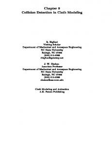
A common way to simplify these computations is to only consider isotropic derivative expressions. In [DES 99], along with linearization of all interactions, this allowed to have a constant matrix H which does not depend on the state of the system, and whose inverse can be precomputed. This is a drastic simplification of the problem for which the "exact" force derivatives are usually anisotropic. However, it sometimes makes sense to alter some purely anisotropic components by adding to them some isotropic contributions. There are two several reasons for this: In some situations, the anisotropy orientation may change drastically from one iteration to another. For instance, an anisotropic elastic force derivative of a spring is only valid of the relative lateral displacements of its extremities remains small compared to the current spring length. While an isotropic derivative approximation would overestimate the force evolution in the case of lateral motion of the edge extremities, the anisotropic exact derivative evaluation leads to an underestimated force not taking into account this lateral displacement (Fig.1). While the consequence of an overestimation is only a stabilization the system through an apparent additional damping, the underestimation has dramatic destabilizing consequences for the reproduction of lateral movements.
Exact computation
Anisotropic extrapolation
Isotropic extrapolation
Fig.1. Computing the force of a spring resulting from a displaced vertex (light) out of the force of an initial position (dark) using anisotropic extrapolation from the derivative at this point (left), isotropic derivative approximation (right), and exact computation (top).
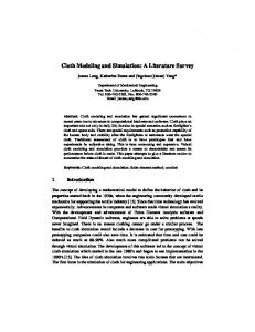
In some simple simulation models, such as those not including any curvature force or damping, global alignment of the particles may cause null derivatives to occur in a given direction orthogonal to all interactions. When anisotropic derivatives are used, this degeneracy causes a singularity in the resolution in that direction, as well as degenerating the equation system. Lateral forces do actually appear along these orthogonal directions if the particles are displaced, although only with a second-order evolution, and thus not represented by first-order derivatives. For instance, the underestimated first-order approximation may lead to totally incorrect equilibrium evaluations in a spring-mass system with almost aligned springs (Fig.2). This however
has to be taken in consideration, as large displacements are to be expected in these directions.
L
L
Fig.2. In a spring-mass system containing almost aligned springs, with the spring rest length L, the computation of the equilibrium position (light) from the initial position (dark) using exact derivatives computed at this point is aberrant.
If any of these problems arise, mostly when dealing with simple spring-mass models that do not contain any curvature effects or any form of damping, a small isotropic component in the derivative computation is often sufficient to prevent instability from appearing. While only considering isotropic components would, more than stabilization, cause excessive and unwanted damping in the system, a linear interpolation between the isotropic and anisotropic is often the best solution to implement.
2.5. Resolution Preconditioning The Conjugate Gradient method is an iterative method that resolves simultaneously and symmetrically the equations of the linear system. The result of the resolution converges to the result of the equation system as the number of iterations increases. The convergence rate on all unknowns and on all equations may however not be the same, depending on the relative importance of each equation and each unknown in the system. Preconditioning is a method to give more relative "importance" to certain unknowns and certain equations in the resolution by multiplying them prior to system resolution. Sometimes, the accuracy requirement is not uniform in the entire object, and some regions of the mechanical system need more accuracy than others. If these regions are quite independent, the best optimization is to perform the system resolution for each region independently. When particles having various accuracy requirements are highly mixed in the system, the best solution is to alter the system resolution through preconditioning techniques. A diagonal preconditioning matrix D should be constructed, for which the diagonal elements are proportional to the relative accuracy required on each particle. Then, instead of solving the system by computing X = H - 1 Y as above, we would rather compute X = D T ( D H D T ) - 1 D Y . While only little complication is added to the computation due to the simple diagonal structure of D , this extra computation could be worthwhile only when very heterogeneous particle structures are used and particular accuracy requirements are necessary on a reduced number of particles.
2.6. Precomputed Matrix Inverses The slowest part of the computation of implicit models is the resolution of the linear system, involving the H matrix, carried out using the conjugate gradient method as described above. However, in some particular situations (notably linear force models and isotropic derivatives), the H matrix can be constant along the simulation steps. An idea resulting from this fact, proposed in [DES 99], is the possibility to pre-compute the inverse of the H matrix, and substitute the linear system resolution by a simple matrixvector multiplication. Unfortunately, the inverse of a sparse matrix is most of the time not sparse. However, as the matrix inverse reflects the effect of a particle's state on any other particle of the system, we can suppose that the particles far away from each other only have minor effects on each other, and the corresponding terms of the matrix can be dropped. It is easy to compute such a sparse inverse approximation by iterating the conjugate gradient method a reduced number of times. The number of non-diagonal elements in each inverse matrix row or columns for a given number of iterations is basically the number of particles linked to a particle by the same number of successive interactions, which, in the case of a flat surface mesh structure, increases quadratically. The interest of pre-computing the inverse of the H matrix can only be justified in small problems where the entire matrix can be computed, or in problems that allow enough approximations that a very reduced number of carefully computed elements of a sparse matrix inverse approximation can be used. However, the conjugate gradient method carries an inherent factorization scheme that allow to process, in a linear number of iterations, the contributions generated from a quadratic number of inverse matrix contributions in the case of a surface mesh structure, and therefore is preferable when high accuracy is required. The conditions required for having a constant H matrix also highly limit the accuracy of a model that would be computed using inverse pre-computation.
2.7. Fast Draping The draping problem is a specific issue where the interest is the final rest configuration of the mechanical system, which has to be computed as quickly as possible starting from an initial configuration. What is important is more the final stable position of the cloth than its evolution. A draping model is implemented as a quasi-static model, where the speed is not taken into account. By removing the speed components in the former equations, we obtain the following system:
P(t + dt ) = P(t ) + H −1 Y
(11)
∂P ′′ 2 dt ∂P Y = P ′′(t ) dt 2
(12)
Where:
H=I−
Here, The "timestep" is more a parameter relating the convergence speed than a parameter really representing time. Very high values can be used, but it may degrade the smoothness of the evolution if the system is significantly nonlinear. This system is solved in the same way using the conjugate or biconjugate gradient method, as described in Part.2.3.
2.8. Increasing Realism While implicit methods help a lot in removing numerical instability for large time steps, they are not necessarily more accurate. The implicit Euler step is not really more accurate than its explicit counterpart, but this inaccuracy is less visible as the system is finally put to a state that corresponds more to the final rest position where forces equilibrate themselves, and which is obtained through the knowledge of force derivatives. Globally, when time steps become too large, the system converges to its rest position as if extra damping removed oscillations excessively. For cloth simulation, curvature is particularly affected, and bending artifacts remain without disappearing through excessive internal viscosity. The effect is quite visible the for simulation of stiff cloth elements, and should be corrected in some ways. Additional accuracy can be obtained through the use of more complex integration methods. Among them, the Rosenbrook method provides an higher order integration accuracy, as well as accurate integration error evaluation [PRE 92]. However, this is obtained at the price of solving four times a linear system of each integration step, which roughly means four times more computation for each time step. While this method seems adapted for accurate and efficient off-line computation, the time necessary for computing one step is really critical for realtime and interactive systems, as this basically rules the number of frames that can be computed during one second of animation, and therefore the visual quality of the animation. For real-time systems, we would rather prefer a "cheap" method that does not complicate computations significantly. A good solution is to use a variation of the implicit Midpoint step. This method considers the evolution during the former step for increasing the accuracy of the current step. Still, only one linear system resolution for each step, bringing accuracy for very little additional computation. The implicit midpoint step is written as follows: ∂P ′ ∂P ∂P ′ ∂P ′ P(t + dt ) P(t − dt ) P ( t ) I − ∂P ′′ ∂P ∂P ′′ ∂P ′ dt P ′(t + dt ) + P ′(t − dt ) − 2 P ′(t )
(13)
P(t ) P(t − dt ) P ′( t ) = 2 dt − 2 P ′(t ) − P ′(t − dt ) P ′′(t )
One drawback of this method is the reduced robustness in the cases of nonlinear problems, which again may become prone to numerical instability. We found a good compromise by introducing a λ coefficient which allows progressively to scale linearly from the implicit Euler step (1) (λ set to 0) to the implicit midpoint step (13) (λ set to 1). Turning into an equation system and after rearrangement similar to (2) (3), we obtain:
P ′(t + dt ) = P ′(t ) + λ(P ′(t ) − P ′(t − dt )) + H −1 Y
(14)
P(t + dt ) = P(t ) − λ(P(t ) − P(t − dt )) + (P ′(t + dt ) − λP ′(t − dt ))dt
Where: ∂P ′′ ∂P ′′ 2 dt − dt ∂P ′ ∂P ∂P ′′ P ′(t ) dt 2 − 2λ (P ′(t ) − P ′(t − dt )) Y = (1 + λ ) P ′′(t ) dt + ∂P
H=I−
(15)
This expression is not significantly more complicated than the simple implicit Euler step (2) (3), and only requires the additional storage of the system state of the former step. For that reason, the computation of the first step of the simulation should be performed with λ = 0 . For most problems, we found the most adequate values of λ ranging from 0.5 to 0.9.
3. Collision Response Collision response can hardly be ignored when performing realistic garment simulation, as the garment has to interact with its environment, mostly through contact effects that prevents object from interpenetrating and also simulates friction. After being detected, mechanical effects of collisions have to be considered in a suitable way. We discuss here an efficient method for performing this integration in the mechanical simulation scheme discussed above.
3.1. Efficient Collision Detection When dealing with complex situations such as multiple cloth parts animated on moving characters such as virtual bodies wearing garments, collision detection is often a bottleneck in the simulation efficiency, and it has to be managed particularly efficiently. In such situations where collisions have to be detected between polygonal meshes that are mostly animated, bounding techniques based on polygon hierarchies built on the meshes seem the best methods, as the hierarchy structure can be kept constant as the surfaces are moving, and only the bounding volumes need to be recomputed between each animation frame. The hierarchical method described in [VOL 94] has been implemented, as it provides additional efficient selfcollision detection within animated surfaces using a surface curvature criteria for testing the possibility of selfcollisions within or between adjacent surface regions of the hierarchy. This method has further been improved by replacing the bounding boxes by bounding polyhedrons as described in [KLO 97]. These bounding polyhedrons are analogous to bounding boxes, but make use of more discriminating orientations than the three axes of traditional bounding boxes, and are thus more able to separate non-colliding parallel surfaces. We found that using the six axes of dodecahedral volumes to be a good compromise for our problem. Though being efficient, such methods are however quite computationally expensive, and are therefore unlikely to be implemented in real-time systems. If the context permits it, it would be more efficient to perform simplified approximate collision detection using some large geometrical primitives enclosing the scene objects, such as
large metaballs whose potential field and gradient determine the collision reactions to be applied on the particles that penetrate them.
3.2. Constraint-Based Hybrid Collision Response Once the collisions have been detected for a given frame, their effects have to be taken into account in the mechanical simulation in order to reproduce contact reaction and friction accurately. There are several ways to include collision effects into a mechanical simulation. The first is to consider collisions as short-range mechanical forces directly handled as such in the mechanical model. The main drawback of this method arises from the discontinuous and nonlinear nature of these forces, that should furthermore be of high intensity. This alters the quality of the mechanical simulation, which then requires timesteps to be small enough to simulate these forces accurately, and this is against the initial advantage of large timesteps brought by implicit integration. The other approach is to integrate the collision response as a direct correction on the state of the system, in a way similar to [EBE 96] or [VOL 97]. Though quite successful with traditional integration methods, this is however a difficult approach to use with implicit methods, as experienced in [BAR 98], because of the lack of "integration" of the collision effects in the integration scheme, which destroys the global stability. We propose a scheme based on correction of the particle acceleration, which can then be interpreted as collision force contributions by the mechanical model, and then have its derivatives integrated along with those of "regular" forces. Given a collision k defined as an interaction between a set of particles i ∈ k, a collision constraint is defined by position and speed constraints between these particles. For instance, these particles should remain at a given distance from each other, or should not have speeds that bring them toward each other. These constraints are applied on collision distance Pk and collision speed Pk' defined as a weighted sum of these properties for all particles i involved in the collision, and weighted by coefficients Ski, as follows:
Pk(t ) = ∑ Ski Pi(t )
Pk′(t ) = ∑ Ski Pi′(t )
i ∈k
(16)
i ∈k
For instance, a collision between two particles would consider these two particles weighted by + 1 and -1. If the collision occurs on polygonal mesh elements, the weights would be the barycentric coordinates of the contact points with the vertices of the respective colliding mesh elements, one of them with opposite sign. Additionally, we can compute in the same way the current "collision acceleration" Pk" resulting from the accelerations of all colliding particles resulting from the mechanical model, as follows:
Pk′′(t ) = ∑ Ski Pi′′(t )
(17)
i ∈k
The collision effect intends to enforce the desired collision position and speed, computed from collision reaction laws (normal component along the collision
orientation) and friction laws (tangential component). We intend to find the collision acceleration correction ∆Pk" to be applied on the collision points so that the collision position and speed reach the desired value after a minimum number of time steps. Because we have two constraints (on a value and on its derivative) to fulfill using only one variable (its second derivative), we need two timesteps to enforce the collision. For finding the required successive acceleration values ∆Pk"(t) and ∆Pk"(t+dt) during these two timesteps, we solve the following linear system: Pk(t + dt ) = Pk(t ) + Pk©(t ) dt + (Pk′′(t ) + ∆Pk′′(t )) dt 2 / 2
(18)
Pk′(t + dt ) = Pk′(t ) + (Pk′′(t ) + ∆Pk′′(t )) dt Pk(t + 2 dt ) = Pk(t + dt ) + Pk©(t + dt ) dt + (Pk′′(t + dt ) + ?) dt / 2 2
Pk′(t + 2 dt ) = Pk′(t + dt ) + (Pk′′(t + dt ) + ?) dt
Pk(t+2dt) and Pk'(t+2dt) being the collision position and speed we intend to obtain after two timesteps, we get: ∆Pk′′(t ) =
Pk(t + 2 dt ) − Pk(t ) 0.5 Pk′(t + 2 dt ) + 1.5 Pk′(t ) − − Pk′′(t ) (19) dt 2 dt
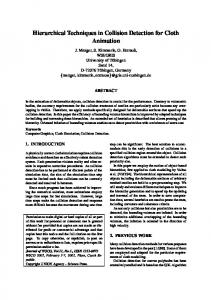
We actually don't need to consider the correction to be applied at the next timestep, as it will be computed when handling the next iteration, hence the "?" term in system (18).
state Pk”(t)+∆Pk”(t) Pk(t+2dt) Pk(t)
Pk’(t+dt)
Pk’(t+2dt)
Pk(t+dt) Pk’(t) t
Pk”(t+dt)+? t+dt t+2dt time
Fig.3. Evolution of a collision from its initial state at time t to its desired state at time t+2dt.
We should now convert the acceleration correction ∆Pk"(t) in terms of extra collision forces ∆ Fi exerted on the colliding particles. We make the assumption that this force is proportional to the weight S k i of the particle in the collision, a true assumption that preserves mechanical momentum in the case of the colliding polygonal mesh elements as described above. Considering that the acceleration correction of a particle is the collision force multiplied by the particle weight, we finally obtain:
∆Fi(t ) = Ski Mi −1 Mk ∆Pk′′(t )
(20)
With Mk being the "reduced mass" of the collision k, computed as follows:
Mk −1 = ∑ Skj2 Mj−1
(21)
j∈k
As for the mechanical model, constrained (nonmechanical) particles can be specified with a null inverse mass on matrices, allowing the definition of the constraint directions. For applying collision response, we need to compute the collision properties using formulas (16) and (17), then compute the collision acceleration correction from the considered collision model using formula (19), and then add the collision force to the mechanical forces exerted on the particles using formula (20). However, for our scheme to be complete, we also need to consider the derivatives of the collision force relatively to the particle positions and speeds. For that, we can easily derive and compute from the considered collision model the derivatives d∆Pk"/dPk and d∆Pk"/dPk', which for most linear collision models are constant values. For instance, when requiring final collision position and speed to match given values, we use the matrices -dt -2 I and - 1 . 5 d t - 1 I respectively. If this constraint is only along a "collision direction" represented by the normalized vector Xk, we multiply these expressions by the projection matrix Xk XkT. Finally, the integration is performed by applying formula (10) directly in the Conjugate Gradient algorithm, by analogy of a mechanical "collision force" involving multiple particles as discussed in Part.2.3, and using as force derivatives the values Vk = Mk d∆ Pk"/dPk and Wk = Mk d∆ Pk"/dPk', computed by considering expression (20). It is also important to note that the scheme proposed here for collision response can be applied for any kind of geometrical constraint that could be defined between particles of the mechanical system, such as attachment points, or "elastics" that pull object regions together.
4. Results
evaluating the performance of our algorithms, in terms of speed and animation quality.
4.1. Cloth Animation The first test intends to measure the performance of the simulation system, as well as the benefits of using the implicit Midpoint method instead of the implicit Euler method. In this test, a hanging square cloth containing 5000 mesh triangles and fixed along one edge balances from an initially horizontal position (Fig.2). The implemented model simulates surface elasticity using the same approach as described in [VOL 97]. No damping was used, so the integration accuracy is viewed on the ability of the system to preserve balancing without excessive damping. Using the implicit Midpoint method with a coefficient λ = 0 . 8 , we obtained a nice balancing with rich wrinkle deformations. In this simulation, most of the damping indeed resulted from kinetic energy dissipation from collisions. Using complete self-collision detection and response, each frame of the simulation is computed in about 0.12 to 0.50 seconds, depending mostly on the collision configuration. Without collision detection, each frame is computed in about 0.10 second a SGI Octane. Using the implicit Euler method (λ = 0), we save an average 10% of the computation time, but the damping artifacts reduce the balancing motion and wrinkle evolution quite quickly. At the other side, instability appear for λ values above 0 . 9 5 , mostly because of the very low bending elasticity used in the mechanical model. This test shows the performance of the model, and how well accuracy can be preserved through the use of the implicit Midpoint method for reducing damping resulting from large step inaccuracy. It however also shows that the most accurate simulation lies on the boundary separating stable methods with over-damping side-effects from very dynamical, but numerically unstable systems.
We have implemented a few test situations for
Fig.2. A balancing 5000 polygon cloth with low damping and collision response.
4.2. The Cube Stack In this layout, an horizontal, soft cloth is constrained at its borders. 128 cubes fall and pile up in an unstructured stack on this surface, which deforms under the weight (Fig.3). The cubes are indeed simulated as soft objects using our model, but their stiffness is high, making them appear almost rigid. The implicit model is able to deal with this stiffness without any significant impact on the whole simulation.
Fig.3. 128 cubes piled on a soft cloth.
This example illustrates the robustness of collision response using the integrated algorithm described in this work. The cube pile, once it has reached equilibrium, remains perfectly stable. While a method based only on state correction, as described in [VOL 97], would be able to manage piles of soft objects, the stiffness of the cube objects would here create instability and "vibrations" because of the highly interacting collisions between the very stiff objects. Using our method, collision effects are actually interpreted as "collision forces" by the mechanical model, and handled concurrently with the mechanical forces for reaching a global equilibrium. The collision response scheme however remains a correction scheme, as these "forces" are actually computed according to the system state which is desired to reach rather than only on the collision geometry. The benefit is an accurate response whatever the mechanical parameters, and a mechanical simulation globally unaltered by the numerous collisions that may occur in cloth simulation. In terms of performances, collision detection accounts for 80% of the total computation time in this scene, because of a collision detection algorithm which is not optimized for numerous small objects moving around, as in this particular configuration. We reach however more than a frame per second of computation on a SGI Octane. The simulation can be considered as "real-time" when less than twenty cubes are present in the scene.
4.3. The Limits of Implicit Methods Having experimented the model on very refined meshes, we have however found that there are some situations where traditional integration methods, such as the RungeKutta method used in [VOL 97], still yield much more accurate results than the implicit methods presented here and in other works.
Implicit methods are low order, meaning that despite their stability, the solution they propose is not necessary an accurate solution, particularly when using large timesteps. Actually, they only ensure stability by "guessing" the equilibrium state of the system (by performing additional computation requiring the knowledge of the state derivatives and system resolution) and converge to this guess when the timestep becomes large. Many dynamical effects may disappear in these approximations, leading to disturbing artifacts such as excessive damping. For instance, having a stiff and very refined hanging cloth rectangle, an implicit method will efficiently pull back displaced vertices to their equilibrium positions with respect to their neighbors, but may completely fail to reproduce global draping effects resulting from gravity and weak curvature forces when using refined meshes and large time steps. The reason is that when high curvature and complex global deformations are involved, the complex and non-linear evolution of the system to its equilibrium state cannot be computed only from the knowledge of the linear derivatives at the current state. The most observable effect are folds and wrinkles that seem not to evolve despite all the interactions exerted on the cloth. In some extreme cases, such a cloth would not even fall through its own weight. You get what you pay for, whatever technique you use for performing the simulation. In the case of explicit methods, you have to pay for the accurate computation of the motion of every particle. This may take a lot of computational resources, but the result will be very accurate through the use of high-order methods describing the whole evolution completely. With implicit methods, you find a way to "cheat" the previous methods in order to allow higher computation inaccuracy without compromising numerical stability that may arise from the local dynamic properties of your mesh, and pay less for a more approximate result (but possibly realistic, as you care only for the macroscopic motion and not for all individual particles). This is obtained through the an evaluation of the equilibrium position, so you have to pay some extra for this knowledge, sometimes quite much, and the first-order approximation you get from the current state might not be valid through all the deformation range you expect. The resulting approximations are likely to prevent the reproduction of complex global dynamic motions of very refined meshes.
4.3. Conclusion The method presented in this paper exhibits very good performances for systems requiring fast or real-time cloth simulation. A particular way of formulating the constraints in a particle system makes its implementation very simple, and various enhancements have been proposed to improve accuracy for rendering dynamic draping as realistically as possible. A very general collision response scheme based on state correction has also been proposed. It is smoothly integrated in the numerical resolution of the mechanical simulation, and therefore provides very good stability, while not altering the simulation performance. Besides collision response, this scheme can be generalized to many other forms of constraints to be exerted on the mechanical system. Our presented method still needs integration in a complete real-time virtual human animation environment,
and this is the topic of the ongoing work. Among the problems to solve, the implementation of a faster collision detection method should replace the current complete polygonal proximity method, which, being accurate for reproducing precise contact for accurate off-line garment simulation, is unable to perform an approximate and fast detection. A better characterization of the simulated mechanical parameters should also be performed This simulation method, being optimized for fast simulation, shows however its limits when considering accurate simulation of complex and refined garments. Possibly, a hybrid simulation scheme merging large-scale high-order explicit integration with local implicit integration would provide a system with universal application domains. There are still many challenging topics to solve in the area of cloth simulation techniques, for these virtual polygonal meshes to be turned into everyone's fashion dreams, real-time, seamlessly.
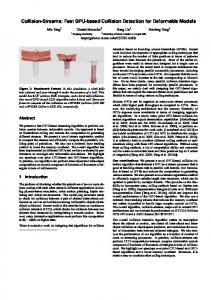
Fig.4. Realistic cloth simulation.
Acknowledgements We are grateful the Swiss Fonds National pour la Recherche Scientifique for funding the projects related to this work, as well as to all the people who contributed to this work, for technical help and suggestions, illustration design and text reviewing.
Bibliography [BAR 98] : D. Baraff, A. W i t k i n , "Large Steps in Cloth Simulation", Computer Graphics (SIGGRAPH’98 proceedings), Addison-Wesley, 32, pp 106-117, 1998. [BRE 94] : D.E. Breen, D.H. House, M.J. W o z n y , "Predicting the Drap of Woven Cloth Using Interacting Particles", Computer Graphics (SIGGRAPH’94 proceedings), Addison-Wesley, pp 365-372, July 1994. [CAR 92] : M. Carignan, Y. Yang, N. M a g n e n a t Thalmann, D. Thalmann, "Dressing Animated Synthetic Actors with Complex Deformable Clothes", Computer Graphics (SIGGRAPH’92 proceedings), Addison-Wesley, 26(2), pp 99-104, 1992. [DES 99] : M. Desbrun, P. Schröder, A. Barr, "Interactive Animation of Structured Deformable Objects", Proceedings of Graphic Interface, 1999. [EBE 96] : B. Eberhardt, A. Weber, W. Strasser, "A Fast, Flexible, Particle-System Model for Cloth Draping", Computer Graphics in Textiles and Apparel (IEEE Computer Graphics and Applications), pp 52-59, Sept. 1996. [EIS 96] : J.W. Eischen, S. Deng, T.G. C l a p p , "Finite-Element Modeling and Control of Flexible Fabric Parts", Computer Graphics in Textiles and Apparel (IEEE Computer Graphics and Applications), pp 71-80, Sept. 1996. [TER 87] : D. Terzopoulos, J.C. Platt, H. Barr, "Elastically Deformable Models", Computer Graphics (SIGGRAPH’97 proceedings), AddisonWesley, 21, pp 205-214, 1987. [VOL 94] : P. Volino, N. Magnenat-Thalmann, "Efficient Self-Collision Detection on Smoothly Discretised Surface Animation Using Geometrical Shape Regularity", Computer Graphics Forum (Eurographics’94 proceedings), Blackwell Publishers, 13(3), pp 155-166, 1994. [VOL 95] : P. Volino, M. Courchesne, N. Magnenat-Thalmann, "Versatile and Efficient Techniques for Simulating Cloth and Other Deformable Objects", Computer Graphics (SIGGRAPH’95 proceedings), Addison-Wesley, pp 137-144, 1995. [VOL 97] : P. Volino, N. Magnenat-Thalmann, "Developing Simulation Techniques for a n Interactive Clothing System", Virtual Systems and Multimedia (VSMM’97 proceedings), Geneva, Switzerland, pp 109-118, 1997. [WEI 86] : J. W e i l, "The Synthesis of Cloth Objects", Computer Graphics (SIGGRAPH’86 proceedings), Addison-Wesley, 24, pp 243-252, 1986. [YAN 91] : Y. Yang, N.Magnenat-Thalmann, "Techniques for Cloth Animation", New trends i n Animation and Visualisation, John Wiley & Sons Ltd, pp 243-256, 1991.