In this paper we report on the evaluation of the feasibility of jetting full gridline contacts to fabricate solar cells without additional plating step. We have ...
IMPLEMENTING NARROW FRONT SILVER GRIDLINES THROUGH INK JET MACHINE FOR HIGH QUALITY CONTACTS TO SILICON SOLAR CELLS 3,1
2
2
2
2
2
2
3
A. Ebong , I. B. Cooper , K. Tate , B. Rounsaville , F. Zimbardi , V. Upadhyaya , A. Rohatgi , M. Dovrat , 3 3 3 E. Kritchman , D. Brusilovsky , and A. Benichou 1
School of Electrical and Computer Engineering, Georgia Institute of Technology, 777 Atlantic Drive, Atlanta, GA 30332-0250, USA 2 Xjet Solar Ltd, 10 Oppenheimer St., Rehovot 76701, Israel 3 Department of Electrical and Computer Engineering, University of North Carolina at Charlotte, 9201 University City Blvd, Charlotte, NC 28223-0001, USA
ABSTRACT In this paper we report on the evaluation of the feasibility of jetting full gridline contacts to fabricate solar cells without additional plating step. We have demonstrated, for the first time, fully ink jetted front Ag gridlines with average line width of only 56.6 µm and height of 30 µm. A high 2 series resistance of 1.1 Ω-cm resulted in average fill factor of 0.767 and led to average efficiency of 18.0% on 2 239 cm commercial CZ wafers with sheet resistance of 65-Ω/sq. This result is very promising and leaves room for improvement, especially with optimized finger spacing, improved ink and co-firing process.
emitters. The cells were printed with the gridline pitch optimized for each emitter. As expected, the emitter component of the series resistance was the same at ~0.54 2 Ω-cm while the short circuit current density was ~0.3 2 mA/cm different. This was due to wider than expected gridlines, which resulted in higher shading on the 85 Ω/sq emitter than the 65 Ω/sq. 0.00
0.01 0.05
0.09
0.15 Rbase Rsheet Rfinger
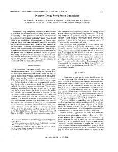
INTRODUCTION The efficiency of a solar cell depends on the bulk lifetime of the materials, surface passivation, and contacts quality. The contact quality encompasses the shading, which must be avoided by narrow and tall lines. The screen-printing technology is not capable of achieving line widths of better than 90 µm in production, even though line height of > 30 µm can be achieved. Thus, metal shading of ~7.5% is the 2 norm for the 156x156 mm solar cells with screen-printed contacts. To reduce the shading to ≤ 5% requires an alternative technology for applying contacts to solar cells. Several approaches including the laser open and plate [1], laser transfer printing (LTP) [2] and extrusion technology [3] have been used. However, the laser buried grooves process is expensive due to additional process steps and high temperature requirements, which is not compatible with low quality materials. Also, the extrusion machine is not yet available. The inkjet print and aerosol approaches have been used to print seed layers followed by light induced plating of silver as a two step approach to achieve narrow gridlines of 65-µm [4-5]. To remove the complexity of plating and the additional step, a full inkjet gridline that can be used in conjunction with the screen-printing technology for rear metallization is investigated. By maintaining the simplicity of screen-printed co-firing process in addition to applying even less metal than the screen-printing will reduce the processing cost. For high sheet resistance emitter with screen-printed contacts, because of the wider fingers, it is impossible to optimize the grid spacing while maintaining the high short circuit current. Figure 1a and 1b compare the series resistance distribution of the screen-printed cells with 65 and 85 Ω/sq
978-1-4244-9965-6/11/$26.00 ©2011 IEEE
Rbus 0.54
Rcontact Rback
Figure 1a: Series resistance distribution for a screen2 printed 65 Ω/sq emitter with values shown in Ω-cm .
0.20
0.00 0.09
0.01 0.12 0.54
Rbase Rsheet Rfinger Rbus Rcontact Rback
Figure 1b: Series resistance distribution for a screen2 printed 85 Ω/sq emitter with values shown in Ω-cm . Because of the line width limitation, the gridline spacing is constrained to values that will not adversely impact the short circuit current while maintaining minimum power loss. This limits the technology to low sheet resistance emitters because the high sheet resistance emitters will require closer gridline spacing to minimize the emitter resistance loss as shown in Figure 1. In order to overcome this limitation, we investigated the use of inkjet to print the full gridlines. Typical average inkjet gridline width investigated in this work is 56.6 µm and height of 36 µm. This will allow the optimization of the gridline spacing with
001050
0.09
0.17 0.01
0.28
0.11
Rbase Rsheet Rfinger Rbus Rcontact Rback
Table 1: Design of experiment (DOE) for investigating the full front ink jetted gridline Dose Finger Finger Bus bar Bus bar contact conductive contact conductive layers layers layers layers 1 10 75 10 20 2 10 60 10 15 3 10 45 10 10
Figure 2: Series resistance distribution for an optimized finger spacing on 85 Ω//sq emitter with 2 values shown in Ω-cm .
FULL INK JETTED GRIDLINE CELL FABRICATION 2
Large area (239-cm ) commercial CZ silicon wafers of 2.6 Ω-cm resistivity were textured, rinsed in dilute HCl before cleaning in H2SO4:H2O2:H2O for 5 minutes, followed by a 3 min rinse in deionized (DI) water. A final dip in 10% HF for 2 minutes was performed, followed by a 30-second rinse in DI water. After the cleaning, the emitters were formed in conventional tube furnace using POCl3 at a set ° temperature of 875 C, which resulted in a 65 Ω/sq emitter. Next edge isolation was performed. After the phosphorus glass removal and DI water rinse, a single layer low frequency PECVD SiN antireflection coating was
978-1-4244-9965-6/11/$26.00 ©2011 IEEE
627.5
36.8 627
Average Voc (mV)
627
627 36.7
36.7 36.6
626.5
36.5
626
36.4
36.4
36.3
625.5
36.2
625
625
36.1 624.5
36.0
36.0
624
35.9 1
2 Dosage
3
Figure 3a: Average VOC and JSC of solar cells fabricated on 60-65 Ω/sq emitters and full ink jetted gridlines. 79.5
1.20
79.3
79.0
Average fill factor (%)
Since Xjet’s inkjet machine is capable of printing even finer lines of ~38 µm, it will be possible to design cells with line spacing similar to lithographically-defined contacted cells. This will enable the contacting of homogeneous high sheet resistance emitter of >100 Ω/sq without light induced plating of silver. Recently, we have demonstrated the capability of the inkjet printing of seed layer (~38 µm wide, 3-4 µm tall) and then plate silver to build the line height to >10 µm and a final line width of ~64 µm [4]. However, plating is an added step that is not desirable by most manufacturers. In order to eliminate the additional plating step, we investigated the full gridline printing with inkjet machine. The implementation of the ink jetted full gridline requires simultaneous printing of two inks – the seed layer ink (3-4 µm) and then full grid ink (10-15 µm). In our previous work of seed layer and plate [5], we found that the seed layer dosage of ~10 was optimally capable of giving good adhesion plus low contact resistance and high gridline conductivity after plating. In this work, we kept the seed layer at 10 dosages and varied the full line dosage. We also kept the line spacing at 1.8 mm, which resulted in 2 92 lines for a 239 cm silicon wafer.
RESULTS AND DISCUSSION
0.96
78.5
0.80
78.3 0.77
78.0 0.49
0.60 77.5
77.5
1.00
77.0
0.40 0.20
76.5
Average series Resistance (Ω Ω cm2)
0.00
°
deposited on the front at 400 C. The wafers were then shipped to Xjet for ink jetting of the front full grid lines. Eight wafers each were printed with three different doses according to Table 1 (Note: the number of layers decreases with the dose). After front gridlines were jetted, the wafers were sent back to GIT. We printed the Al back ° and dried at 200 C before printing the Ag/Al stripes and dry. The samples were co-fired in the IR belt furnace after a controlled profile to ascertain the peak firing ° temperature, which ranged from 730-785 C. The light I-V measurements were carried out.
Average Jsc (mA/cm2)
minimum shading and resistive losses. For instance, a 2 large area cell (239 cm ) with 85 Ω/sq emitter will require 102 lines to combat the emitter resistance and metal coverage of < 6% (See Fig. 2). Thus > 80% fill factor and 2 short circuit density of ~37.6 mA/cm . The finer gridline will also lead to improved open circuit voltage of 632 mV because of the reduced emitter recombination and hence an efficiency of > 19%.
0.00 1
2 Dosage
3
Figure 3b: Average fill factor and series resistance of solar cells fabricated on 60-65 Ω/sq emitters and full ink jetted gridlines.
001051
lower series resistance, higher fill factor and efficiency would be achieved as shown in section 1.
17.9
Average Efficiency (%)
17.9
17.9
17.9
17.9
17.8 17.8 17.8
17.8
17.8 17.8
1
2
3
Dosage
Figure 3c: Average efficiency of solar cells fabricated on 60-65 Ω/sq emitters and full ink jetted gridlines. Fig. 3a to 3c show the cell light I-V characteristics for the dosage DOE. Fig. 3a shows that the JSC increases with decreasing ink dosage, while Fig. 3b shows that the fill factor decreases with decreasing ink dosage because of increased series resistance. However, despite the reduced fill factor, because of the increased JSC, the efficiency was almost the same. This demonstrates that less Ag can be used without losing the cell performance.
Figure 5: Full ink jetted gridline having width of 56.6 µm and height of 36 µm. Table 2: Measured light I-V and extracted electrical parameters from IQE measurements and PC1D calculations for full front ink jetted gridline cell. Cell parameters Measured Modeled Base Resistivity (Ω -cm) 2 Rs (Ω-cm ) 2
Rsh (Ω -cm ) n2
Figure 4: Gridlines for the three different doses (1-3) after contact co-firing. Scale bars represent 2 µm. Fig. 4 shows the micrographs of the gridlines for the three doses (from left to right). Dose 1 gave the highest height (45 µm) and widest line followed by 2 and then 3. That leads to higher shading for the dose 1 and hence the lower Jsc and Voc. However, the low series resistance and the high fill factor (79.3%) compensated for the low JSC and resulted in highest efficiency of 17.9%. On the other hand, dose 3, which gave the highest series resistance with lowest fill factor (77.5%), resulted in less shading and highest JSC and resulted in efficiency of only 0.1% lower. Therefore, we chose this dosage for further experiments. Cells with optimized dosage Table 2 shows the measured light I-V and extracted electrical parameters from IQE (Fig. 6) measurements for the full gridline jetted cell using number 3 dose. JSC is 2 higher by 0.8 mA/cm than the previous case because of the narrower average gridline width of only 56.6 µm (Fig. 5), which gave shading of ~6%. The low fill factor is due to the high series resistance, which is probably due to nonoptimum contact firing. With optimum contact firing and
978-1-4244-9965-6/11/$26.00 ©2011 IEEE
2.6 1.12
2.6 1.12
10917
10917
1.04
2
Jo2 (nA/cm )
2
13
13
Emit sheet resistance (Ω/sq) Surface concentration -3 (cm ) Diffusion length (µm)
60
60
Wafer thickness (µm)
1.5x10
20
1.5x10
928
928
180
180
BSRV (cm/s)
20
300
BSR (%)
71
FSRV (cm/s)
51,000
Grid shading (%)
6.0
6.0
Modeled Voc (mV)
627
627.9
Modeled Jsc (mA/cm )
37.4
37.7
Modeled FF (%)
76.7
76.9
Modeled Efficiency (%)
18.0
18.2
2
IQE Characterization of the 18% full ink jetted solar cell Fig. 6 shows the modeled and experimental internal quantum efficiency (IQE) for the 18% cell with full front ink jetted gridlines. From the PC1D simulation we calculated the front surface recombination velocity (FSRV) to be 51,000 cm/s and back surface recombination velocity (BSRV) as 300 cm/s. Table 2 lists the PC1D calculated
001052
values for the cell. The measured and the calculated VOC, JSC, fill factor and efficiency agreed well.
We have designed and fabricated 18% efficient solar cell with full jetted front gridlines for the first time. Before the jetted full lines, the seed layer was deposited to ensure uniform etching of underlying silicon nitride and formation of good contacts and adhesion. The full line was designed to keep the line conductivity high so that the line resistance component of the total resistance is minimal. Three doses for the full gridline were investigated and we found that the lowest dose was beneficial in producing high JSC and moderate fill factor. This optimized dose for the full jetted line resulted in 56.6 µm line width and 36 µm 2 line height, which led to JSC of 37.4 mA/cm on a 65 Ω/sq emitter. Based on this result, and PC1D calculations it is possible to achieve > 19% full jetted gridline solar cells as we showed in our efficiency roadmap.
100 90 80
IQE (%)
70 60 50 Internal Quantum Efficiency
40
Experimental Data
30 20 10 0 300
380
480
580
680
780
880
980 1080 1180
REFERENCES
Wavelength (nm)
Figure 6: Modeled and experimental IQE match for the 18% full gridline ink jetted cell. Toward higher efficiency with full jetted gridline
20.0
19.6 19.3
19.5 19.0
CONCLUSIONS
18.6
18.5 18.0 18.0 17.5 17.0 16.5 16.0 15.5 15.0
[1] D. Kray, N. Bay, G. Cimiotti, S. Kleinschmidt, N. Kosterk, A. Losel, M. Sailer, A. Trager, H. Kuhnlein, H. th Nussbaumer, C. Fleischmann, F. Granek, 2010, 35 IEEE PVSC. [2] www.schmid-group.com/en/photovoltaic/cell/lasertransfer-printing.html [3] High speed printing technology for silicon photovoltaic wafer processing: Breakthroughs in efficiency and yield, PARC, www.PARC.arpaesummit2010 [4] A. Ebong, B. Rounsaville, I. B. Cooper, K. Tate, A. Rohatgi, S. Glunz, M. Horteis, A. Mette, M. Gundermann, Xjet, “High efficiency silicon solar cells with ink jetted seed and plated grid on high sheet resistance emitter”, 2010, IEEE Proceedings, paper 312. [5] A. Ebong et al, “Ink jetted seed and plated grid solar cells with homogeneous high sheet resistance emitters”, 2010, 35th EUPVSEC.
Present full jetted Optimized firing Improved FSRV Optimized grid cell (FSRV=52,000 (FSRV=52,000 cm/s; (FSRV=25,000 cm/s; (FSRV=25,000 cm/s; cm/s; BSRV=300 BSRV=300 cm/s; BSRV=300 cm/s; BSRV=300 cm/s; cm/s; Rs=1.1; Rs=0.72; FF=0.792; Rs=0.72; FF=0.793; Rs=0.50; FF=0.806; FF=0.767; 6% 6.0% shading) 5% shading) 4% shading) shading)
Figure 7: Efficiency roadmap for the full jetted gridline solar cell. Fig. 7 shows the efficiency roadmap for the full jetted gridline solar cell. The first full jetted gridline cell is affected by the high series resistance, which resulted in low fill factor and hence only 18% cell. The high seires resistance is attributed to non-optimum firing and possibly non-optimum ink. With optimized ink and co-firing, the fill factor of 79.2% can be achieved and that will lead to 18.6% efficiency on the 65 Ω/sq emitters. By increasing the emitter sheet resistance to ≥ 85 Ω/sq and improvement of front surface passivation to 25,000 cm/s, the efficiency of 19.3% can be achieved, provided other optimized parameters can be kept. Finally, when the line width of ≤ 45 µm is adopted, which will give shading of ~4% in conjunction with the high sheet resistance emitter and low FSRV, efficiency of 19.6% will be realized.
978-1-4244-9965-6/11/$26.00 ©2011 IEEE
001053