Prognostics. Sony Mathew, Michael Osterman and Michael Pecht. Center for Advanced Life Cycle Engineering (CALCE). University of Maryland, College Park,.
Considerations in Implementing Canary Based Prognostics Sony Mathew, Michael Osterman and Michael Pecht Center for Advanced Life Cycle Engineering (CALCE) University of Maryland, College Park, MD 20742 www.calce.umd.edu www.prognostics.umd.edu Abstract—The concept of using canary devices to predict the failure of a system is gaining momentum but there are practical issues that challenge the mainstream implementation of canary device based prognostics. This paper provides a general methodology for implementation of the canary based prognostics. This paper presents an approach to tackle practical issues including determining the number of canary devices required and the confidence in the prediction for a particular number of canaries. A failure prediction scheme to estimate system failure based on the failure of the canary device in the field, is also presented in this paper.
the time to failure of the canary device and the actual system is referred to as prognostic distance [3].
Keywords- Canary design, number of canaries, failure prediction scheme, prediction confidence.
This paper presents a failure prediction scheme based on the time to failure of the canary, which also addressed the issue of prediction when the field use conditions vary from the design considerations. A methodology to determine the confidence in the number of canaries implemented is also presented in this paper. A general methodology to select and design a canary device is also presented herein.
I.
INTRODUCTION
Historically coal miners used a canary bird in the coal mine to detect poisonous gases. The canary birds being sensitive to even low quantities of hazardous gases served as an early warning system for the coal miners. The sickening of canary birds indicated the presence of poisonous gases in the mines, thereby forcing the miners to take corrective action and exit the mine. The concept of using an embedded device that is relatively more sensitive to the operational and environmental loads than the rest of the system is an attractive option in the field of prognostics and health management. The canary device provides early warning of system degradation. Under the same environmental and operational loading conditions, the canary device fails faster than the target system [1]. The amount of degradation of the target system is a function of the sensitivity of the canary device to the environmental and operating loading condition. Ideally it would be worthwhile to have the canary device fail by the same failure mechanism as the target system. The canary device must also fail prior to the target system. This helps with the root cause identification and appropriate health management activities being implemented to increase the system availability and reliability. In instances where there exists a clear mapping between the failures of the canary devices to the failure of the target system, then it does not matter if the mechanisms match [2]. The difference between 978-1-4799-1894-2/15/$31.00 ©2015 IEEE
Mainstream implementation of canary devices to predict system failures are challenged by practical implementation issues including how to select and design the canary device, what failure prediction scheme to be used to correlate canary failure to system failure, and the number of canaries to be implemented to obtain a prediction with a high degree of confidence.
II.
CANARY DEVELOPMENT METHODOLOGY
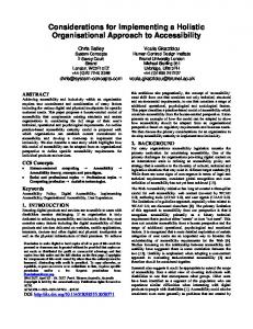
Figure 1 shows a general methodology for developing a canary device for prognostics. Conducting a failure modes, mechanisms, and effects analysis (FMMEA) [4] of the target system is crucial to developing a canary device. An FMMEA will help in identifying all the possible ways in which the target system can fail under its life cycle environmental loading conditions. A detailed step by step process of performing a FMMEA has been presented a study conducted by Mathew et.al, [5]. The FMMEA may help uncover multiple failure mechanisms that affect the target system depending on the application and life cycle loading. To narrow down the canary designs it is necessary to select the most critical mechanism(s) under the operational loading conditions. Likewise it is necessary to identify which component/ sub-assembly in the target system is the most susceptible to failure. Ideally the canary device should be designed to mimic the failure of the component most likely to fail in the target system. Step three is to select the type of canary device to be used to monitor the target system. The designer can choose
according to the need, whether the canary device should be an expendable canary, sensory canary, or a conjugate-stress canary [6]. Expendable canary devices are designed such that once a device fails it is no longer operational. Sensory canary devices are designed to be more sensitive to loading conditions and degrade at a higher rate at lower load levels than the host system. Conjugate-stress canaries are based on simultaneous identification of conjugate-stress pairs.
device and the associated target system. N1 = Time to failure of 1 % of population, N50 = Time to failure of 50 % of population, and N99 = Time to failure of 99 % of population. For a given distribution of TTF of target system and canary the PD can vary depending on the PD scheme selected. PD1 is the difference between the N1 of the target system and N99 of the canary. PD2 is the difference between N1 of target and N50 of canary. PD 3 is the difference between N50 of target system and N99 of canary. PD 4 is the difference between N50 of target system and N50 of canary. For a given distribution of TTF of target system and canary the PD can vary depending on the PD scheme selected. The issue facing the implementation of canary based prognostics is to determine when the target system will fail under operational conditions. Here a new term is introduced in the form of the ‘Product to Canary Ratio’. The product to canary ratio (PCR) is the ratio of time to failure of product to time to failure of the canary. The PCR values are estimated at the design phase based on the estimates of the PoF models. The PoF models used to design the canary will present a TTF estimated depending on the input parameters to the model. Likewise the PoF model applicable to the target system will generate a TTF for the target system.
Figure 1: Methodology The next step is to design the canary device. If the selected canary is an expendable canary, then that canary device should be designed such that it fails by the same failure mechanism as the target component. If it is a sensory canary, then the canary must be designed to be more sensitive than the target component to rising loading conditions that would cause the target component to fail and then provide sufficient warning of such a rise in loads. It is important that the canary be designed on the basis of a physics of failure model that accounts for the factors that influence the failure mechanism of the product. It may be necessary to conduct finite element analysis to develop and update the model parameters. After the canary device has been designed, it is necessary to conduct prototype testing and validation of the concept. Once the canary design and development process is complete it is necessary to set a failure prediction scheme so as to relate the time to failure of the canary to the remaining useful life and time to failure of the target system. In the following section a failure prediction scheme is proposed which can adjust to changing operational situations experienced by the target and canary systems. III.
Figure 2: Multiple prognostic distances Equations 1 through 5 show the different PCR values based on times to failure.
(1) (2)
(3)
(4)
FAILURE PREDICTION SCHEME
The prognostic distance (PD) is the difference between the time to failure (TTF) of the target system and the TTF of the canary [3]. Figure 2 shows a schematic representation of the probability distribution of time to failure for a canary
(5) There are two possible scenarios that can occur in operational conditions: Case 1) the target system and canary are operated under a fixed loading condition and fixed loading
range. (Example: temperature cycling condition -55oC to 125oC with 15 min dwell), and Case 2) the loading condition for the target system and canary are known but the loading range varies. (Example: System subjected to temperature cycling loading, but temperature range is not known due to lack of ability to monitor environmental loads). A. Operational Case 1 The type of loading and the load range are known. The target system and canary are operated in the fixed loading condition and loading range. In this study the target system (BGA) and the canary device (resistor with reduced solder attachment area) are subjected to temperature cycling condition -55oC to 125oC with 15 min dwell. In this case the TTF of the target system can be estimated by multiplying the relevant field TTF statistic for the canaries with the corresponding PCR value. For example if during the development process, PD4 is selected as the required prediction estimate, then the TTF of the target system can be estimated by multiplying the relevant field TTF statistic for the canary device with the corresponding PCR value (see Equation 6). Since the loading condition and range are fixed, the failure of the canary device will also serve as a validation of the PoF estimate. (6)
Where x = desired failure probability value, β = shape factor of 2-parameter weibull distribution, Δγ is the cyclic plastic shear strain range, εf is the fatigue ductility coefficient, and c is the fatigue ductility exponent. The effective ΔTA can be then used in the PoF model for the target system to predict its life under actual field conditions The effective acceleration factor (AF) for the canary device can be estimated as shown in equation 8. (8) In Approach 2, no assumptions are made about the dwell time and mean cyclic temperatures. Since there are three unknown values: temperature difference (∆T), mean cyclic temperature (Tsj), and dwell time (td) at extremes, data needs to be collected to solve for these three values. Three canary devices each with varying solder pad area, but different form each other should be designed and incorporated along with the target system in the field. The three canaries are designed to fail at different times but all fail before the target system. Under operational conditions when all three canaries fail, the TTF information for each canary can be used to generate three equations with three unknowns. The TTF information can be substituted in the equation 9 below.
B. Operational Case2 The type of loading is known but there is no information about the loading range. Assume the target system (BGA) and the canary device (resistor with reduced solder attachment area) are subjected to temperature cycling conditions but the loading range and dwell time is not known. In such a scenario the PCR statistic cannot be employed since the PCR values will be different for different loading ranges for the same loading condition. For this specific loading condition (temperature cycling) there are two different approaches to estimate the TTF of the target system. Approach 1assumes that the dwell time, and mean cyclic temperature in operational conditions is the same as the dwell time, and mean cyclic temperature used during the design phase to design the canary. Let ΔTD = design condition temperature difference, and ΔTA = actual field temperature difference. The time to failure Nf(ΔTD) for the canary device can be estimated using the Engelmaier’s model with calibrated first principles strain equation [2]. The Nf(ΔTA) for the canary is obtained from the field data. As per the assumption the dwell times and mean temperature don’t change, hence the effective ΔTA can be back calculated from the probabilistic Engelmaier’s equation [7] with the calibrated first principles strain formula. Given the TTF values for the canary device, Equation 7 (probabilistic Engelmaier’s model) can be used to back calculate the temperature difference. (7)
(9) Solving the three equations with three unknowns, the values of the ∆T, Tsj, and td can be calculated. Using the calculated ∆T, Tsj, td values in the PoF model for the target system, its life under actual field conditions can be predicted. The next challenge is to determine the confidence in the prediction obtained from implementing canary devices. The confidence in the prediction is a function of the number of canary devices implemented to predict the failure of the system. The following section presents a procedure to determine the confidence in the prediction. IV.
CONFIDENCE IN NUMBER OF CANARY DEVICES SELECTED
Confidence in the prediction of life of Target will depend on η (characteristic life) and β (shape parameter) of the two distributions (TTF of canary and TTF of target) in time and the selected PD scheme. Let, βT = Shape parameter for Target, ηT = characteristic life (scale parameter) for Target, βC = Shape parameter for Canary and ηC = characteristic life (scale parameter) for Canary. If the η of the distributions are close then there is a possibility that the distributions intersect, i.e. for a fixed βC, as the ηC increases the probability that the canary will fail after the Target System increases. Figure 3 illustrates the case of increasing η. Also, if the β (shape parameter) of the distributions are small then the TTF data is spread over a larger time period and there is a possibility that the
missing Target System failure for 1st set of TTF data for 3 canaries, 2nd set of TTF data for 3 canaries, and so on till the probability has been calculated for all data sets for each selected number of canary device.
distributions will intersect, i.e. for a given ηC, as the βC decreases the probability that the canary will fail after the Target System increases. Figure 4 illustrates the case of decreasing β. If the two distributions intersect then there is a probability that the canary may fail after the target system. It is therefore important to find out the probability of the canary failing after the target system fails.
5.
Plot the distribution of probability of miss for each selected number of canary devices. Ex. Plot the pdf of all probability of miss for 5 canary devices.
6.
Next plot the reliability (probability) of achieving the “probability of miss” for each number of canary devices. Ex. Generate a plot of probability on the y axis and probability of miss on the x axis for 7 canary devices.
7.
Estimate the probability that a given number of canary devices will have a probability of miss equal to the set threshold. Ex. The probability that a 1 % target system failure will be missed if 3 canary devices are used is 10%.
8.
Plot the probability of the “Probability of Miss” versus the number of canary devices.
9.
This plot will help determine the confidence in the number canary devices that is chosen to be incorporated in the target system.
Figure 3: Effect of changing ηC
Figure 4: Effect of changing βC A. Procedure To have confidence in the target system failure prediction using a given number of canaries, it is necessary to identify the probability of missing the target system failure. It is proposed that to estimate the number of canaries required for generating a prediction of TTF of the target system, an analysis of the probability of missing the failure of the target system be conducted prior to implementation of the canary approach. The following is a procedure to generate the confidence in the number of canaries. 1.
Select an acceptable threshold value for the probability of missing target system failure. Ex. For a particular application the acceptable probability of missing target system failure is = 1 %.
2.
From the prototype validation and testing stage of the Methodology for Canary Prognostics, determine the β and η of Target System and the Canary Device.
3.
Using the β and η statistic for the Canary device conduct a Monte Carlo simulation to generate multiple sets of time to failure (TTF) data for varying number of canary devices. Ex. 20 sets of TTF data for 3, 5, 7…etc. canary devices.
B. Calculating Probability of Missing Target System Failure Consider two extreme cases for a given βT and ηT: 1) if the βC is high and ηC is much lower than ηT, then the probability of miss is very low. In such a case the difference in the Probabilities from step 8 will be small for different number of canaries. In such an event implementing the least number of canaries makes sense. 2) if the βC is low i.e. the TTF data has a wide spread and ηC is much closer to ηT, then the probability of miss is very high. Here the difference in the Probabilities from step 8 will be large for different number of canaries. Here more number of canaries may have to be implemented or the canary design has to be changed to reduce the probability of miss. Consider the case of using a resistor with reduced solder attachment area as a canary for predicting the failure of a BGA = probability of that TTF of Canary (target system). Let exceeds TTF of Target, = probability of that TTF of Target exceeds TTF of Canary, and Rcanary = reliability of canary device. (10)
4.
Calculate the probability of missing the target system failure for each set of canary TTF data for each selected number of canary devices. Ex. Calculate probability of
(11) The probability that the canary will fail before the target is estimated by solving the equation 12 shown below.
(12) Where PM = P [TTF of Canary ≥ TTF of Target]
TABLE II.
20
15
10
5
3
Run 1
5.91
3.75
2.78
2.77
7.8
Run 2
7.52
6.81
4.7
4.47
4.6
Run 3
8.93
5.63
3.27
6.26
2.91
Run 4
7.79
6.54
6.19
4.35
3.6
Run 5
3.44
6.25
5.11
4.04
3.19
Run 6
4.3
4.32
3.61
5.61
4.31
Run 7
10.06
2.52
5.76
6
4.52
Run 8
7.98
3.7
4.45
3.55
5.32
Run 9
9.8
7.95
2.89
2.94
1.4
Run 10
9
5.36
7.11
7.64
2.5
Run 11
8.22
6.33
4.56
3.95
2.78
Run 12
7.16
7.29
5.38
4.22
3.9
Run 13
4.52
5.86
5.16
3.78
2.87
Run 14
4.41
4.05
6.24
6.11
4.12
PRIOR EXPERIMENTAL DATA
Run 15
4.15
7.51
3.88
7.05
5.16
Characteristic life η (Cycles)
Shaper parameter β
Run 16
7.22
6.24
6.11
4.68
2.99
Run 17
6.15
5.99
5.23
5.17
3.67
718
3.92
Run 18
4.95
5.37
5.49
3.88
4.05
1606
3.875
Run 19
2.11
3.38
2.96
2.87
5.56
Run 20
3.45
5.11
5.76
2.66
5.28
(13)
(14) (15)
(16) C. Case Study An example of conducting an analysis to estimate the number of canaries is presented here. The target system is a BGA with tin-lead solder interconnects. The target system is a BGA is a chip array ball grid array (CABGA) with 192 IO. The canary device is a 2512 resistor with solder pad width reduced to 20% of regular width and with tin-lead solder. Experimental data is available for the time to failure of the BGAs and resistors under temperature cycling loads of -55oC to 125oC with 15 min dwell. The threshold for the probability of missing target system failure is set at 5%. Table 1shows the test data statistics for the BGAs and resistor. TABLE I. Component Resistor (Canary) 192 IO BGA (Target System )
TABLE TYPE STYLES
Data Generation Rum
For this analysis data was generated using the Monte Carlo data generation function in Weibull++ software. Equation 17 shows the formula to generate the data points.
(17) Where β = shape parameter (or slope), η = scale parameter (or characteristic life), LN = natural logarithm, N = an instance of time to failure and RAND () is a random number generator function. For this analysis the inputs to the equation are the η and β values from experimental data of resistors and BGAs as shown in Table 1.
Number of Canaries
The probability of missing the BGA failure is low irrespective of the number of canaries used (provided canaries fail with a fixed β). The reason is the difference between characteristic life (η) of canary device and the target systems. Figure 5 shows an example of a plot of the interference of the distributions of the 20 canaries and the target system. Figure 6 shows the same plot with 5 canaries and target system.
For the canary device twenty sets of 20, 15, 10, 5 and 3 data points were generated, while for the Target system only one set each of 20 data points were generated. For the canary device for each data set the N50 and N99 at 95% confidence level was calculated while for the target system, the N1 and N50 at 95% confidence level was calculated. The probability that the canary will fail before the target is estimated by solving the equation 12. Table 2 shows the probability of missing the target system failure if 20, 15, 10, 5 or 3 canaries are used to monitor the target system. Figure 5: Twenty canaries vs target system (Run 1)
Figure 7 shows the reliability (probability) versus probability of miss for the selected number of canaries. The probability of probability of miss ≤ set threshold (5%) versus the number of canaries selected is plotted in this figure. Figure 8 gives the confidence in implementing the specific number canaries. It can be seen that as the number of canaries increases the probability of getting the Probability of Miss increases. V.
Figure 6: Five canaries vs target system (Run 4)
Figure 7: Probability of Probability of Miss [2]
SUMMARY AND CONCLUSIONS
A general methodology to select and develop a canary device is presented in this paper. A failure prediction scheme and a procedure for determining confidence in the life prediction are also proposed herein. For a given distribution of time to failure (TTF) of target system and canary, the prognostic distance can vary depending on the PD scheme selected. The product to canary ratio (PCR) values are estimated at the design phase based on the estimates of the PoF models. The field TTF for the target system can be estimated by multiplying the relevant field TTF statistic for the canaries with the corresponding PCR value. Approaches to predict field failure of the target system when the field conditions are not known have been presented herein. If there is only one canary device the confidence in the prognostic distance is low since the failure could be on any side of the Canary TTF distribution. As the number of canaries increase the confidence in the prediction will increase because the TTF information is in the form of a distribution. Practically it is not feasible to have too many canaries to monitor just 1 target system. In case the distributions of the canary and the target are close, there is a probability that the TTF of the canary may exceed the TTF of the target. Monte Carlo simulations can help estimate the effect of number of canaries on the probability of missing the target system failure. The number of canaries deployed will depend on the acceptable probability of missing the target failure, the required accuracy of prediction and cost of canaries. The methodologies and procedures presented in this paper offer a path to tackling practical challenges in implementing a canary device based prognostics approach. While the examples presented do not deal with complex system interactions and a wide operating scenario, these techniques can be used as a starting point for complex scenarios. REFERENCES [1] [2]
[3]
Figure 8: Number of canaries Vs Probability of Miss [2]
[4]
M. Pecht, Prognostics and Health Management of Electronics, WileyInterscience, New York, NY, August 2008. Mathew, S., “An Analytical Model for Developing a Canary Device to Predict Solder Joint Fatigue Failure Under Thermal Cycling Conditions”, 2014 PhD. Dissertation, University of Maryland, College Park, MD. Mathew, S., Osterman, M., and Pecht, M., “A Canary device Based Approach for Prognosis of Ball Grid Array Packages”, IEEE International Conference on Prognostics and Health Management, Denver, CO, 18 – 21 June, 2012. Ganesan, S., Eveloy, V., Das, D., and Pecht, M. “Identification and utilization of failure mechanisms to enhance FMEA and FMECA”.
[5]
[6]
[7]
Proceedings of the IEEE Workshop on Accelerated Stress Testing & Reliability (ASTR), Austin, Texas, October 2–5, 2005. Mathew, S., Alam, M., and Pecht, M., “Identification of Failure Mechanisms to Enhance Prognostics Outcomes”, ASM Journal of Failure Analysis and Prevention, Vol., 12 Iss., 1, pp: 66-73, 2012. Dasgupta, A., Doraiswami, R., Azarian, M., Osterman, M., Mathew , S., and Pecht, M., “The Use of Canaries for Adaptive Health Management of Electronic Systems”, ADAPTIVE 2010, IARIA Conference, Lisbon Portugal, Nov 21-26, 2010. IPC Association Connecting Electronics Industries, IPC-D-279, “Design Guidelines for Reliable Surface Mount Technology Printed board Assemblies”, Northbrook, IL, July 1996.