ShieldIP, Inc. AT&T LabsâResearch UMass Amherst. Abstractâ ..... video sessions, as opposed to dedicated measurement sessions.) ... We call this thinning. In.
Impromptu Measurement Infrastructures using RTP Ram´on C´aceres ShieldIP, Inc.
Nick Duffield Timur Friedman AT&T Labs—Research UMass Amherst
Abstract— Dedicated infrastructures for end-to-end measurements are complex to deploy and manage. Equipment cost, the requirements for reporting bandwidth, and the administrative diversity of the Internet, are factors that potentially hamper scalability. This paper describes the architecture and implementation of an alternative approach in which the end-to-end probing and measurement reporting functions are embedded in a transport protocol, namely RTP. Suitably enabled hosts in a multicast group are effectively co-opted to form an impromptu measurement infrastructure. Coupled with our previous work on multicast-based inference, this enables the determination of the performance characteristics of internal network links of very large multicast distribution trees. Our experimental results show that an accuracy of about 1 part in 10 is attainable when inferring link loss rates in the 1% to 10% range, down to 1 part in 3 for loss rates down to 0.1%, this for probes generated by a regular audio source over a few hundred seconds.
I. I NTRODUCTION A. Motivation The past few years have seen the development of new techniques to infer network characteristics from measurements. Known loosely as “network tomography,” they supply detailed information about a set of individual characteristics that are not directly measurable, from a set of aggregate characteristics that are measurable. So far, two cases have been examined: the inference of origin-destination traffic matrices from measurements of link traffic intensities (see [5], [27], [29]), and the inference of link performance characteristics (e.g., loss, delay and utilization) from end-to-end measurements. In this paper we are concerned exclusively with the second case. For the purpose of determining network performance, tomography of link characteristics contrasts with techniques that rely upon support from routers or other agents located in the network to collect measurements. While such techniques can be very effective, they do depend upon the observer having privileged access to the network. Even with such access, specialized agents (e.g., packet monitors) can be expensive to deploy. Another issue is that some low-level network elements (e.g., repeaters in cable networks) do not even keep operational statistics. With the administrative diversity of the Internet, a given network operator will not have privileged access along the entire end-to-end path that their customers’ traffic traverses. Commercial sensitivity may act as a barrier to the sharing of internal network data across administrative domains. End-host based tools such as ping, traceroute, and pathchar [9], [21] do not require privileged access to the network. However, they provide relatively coarse information about individual link behavior, they rely to some extent on the cooperation of the network (in enabling ICMP responses), and their use does not scale easily to provide a network-wide snapThis work was supported in part by DARPA and the AFL under agreement F30602-98-2-0238
shot. All these considerations motivate the need for a technique that can provide a wide snapshot of network performance based only upon end-to-end measurements of regular network traffic. Multicast-based Inference of Network Characteristics ( MINC) has recently been proposed as a technique for tomography of link characteristics; see [1] for an expository account. The basis of the technique is that end-to-end measurements along a set of intersecting network paths can be correlated in order to infer the performance characteristics of the intersection. Multicast traffic is particularly well suited due to its inherent correlation properties. Consider a multicast packet dispatched from a source, down a multicast tree, to a number of receivers. The end-toend behavior for the packet as seen at the receivers is correlated since the contribution from the common portion of the end-toend paths is identical. On the basis of this idea, statistical estimators have been developed to estimate the characteristics of the logical links of the multicast tree from end-to-end measurements between the source and the receivers, in particular packet loss rates [3], delay distributions [17], delay moments [12], and even the underlying logical topology [10]. Using clusters of unicast packets to emulate multicast packets, it is possible to draw the same type of inference from unicast measurements; see [7], [13]. Realization of MINC in the Internet must address two issues: the availability of participating end-hosts, and the transmission of measurement data from the end-hosts to a common location for correlation and inference. To date, MINC has been deployed on a measurement infrastructure comprising a number of hosts (approximately 50 as of mid 2001) either dedicated or co-opted for measurement. Scheduling and coordination of the measurement and data transmission functions of these hosts is managed using the National Internet Measurement Infrastructure ( NIMI) [19]. While we find that a fixed infrastructure provides a great many benefits, especially in terms of stability and reliability, dependence upon specialized hosts limits the possibilities for MINC to become a ubiquitous tool, due to the hardware costs and administrative issues of their deployment. More generally, control of the transmission of measured data to a common point for inference also becomes an issue for widespread deployment, due to the potential “implosion” problem: the common point will have an incoming stream of data that grows linearly both in the number of receivers and in the data rate of the original sender. These considerations motivate the need for a scalable deployment of MINC that does not require specialized end hosts, and that can globally limit the transmission volume of measurement data. B. Contribution and Outline In this paper we use the Real-Time Transport Protocol ( RTP) [25], and its control protocol ( RTCP), as the vehicle for MINC
probing and measurement reporting. R TP carries multicast audio and video traffic over the Internet. The regular packet stream from a multicast source comprises the MINC probe stream. RTCP receivers periodically multicast reports back to the group for the purposes of transmission control. Exploiting RTCP’s flexibility, we extend it to include per-probe measurement data in these reports. Embedding MINC in RTP provides several benefits. Firstly, any RTP multicast session can act as a source of MINC probes without modification to the senders. Secondly, the MINC extension to RTCP is transparent to the receivers, and can be incorporated in a receiving application simply by relinking that application to an extended RTP library. Sessions can freely accommodate a subset of MINC-enabled receivers amongst unenabled receivers. This flexibility allows a potentially large number of session participants worldwide to participate easily in the measurement process. Thirdly, since RTCP reports are multicast, any third-party host may monitor reports and perform MINC inference. Lastly, we can take advantage of RTCP’s built-in scaling to avoid feedback implosion. Together, these features allow us to co-opt large numbers of Internet hosts to form an impromptu measurement infrastructure. The embedding of MINC into RTP can be of use to adaptive applications. They could use knowledge of the location of lossy links, for instance, to dynamically assign servers to retransmit lost packets to receivers located behind those links. If the embedding imposes little overhead, then it could be used routinely in RTP even by applications that do not themselves need to perform inference. In this case a third-party passive monitor could perform inference on the reports from a number of sessions on which the MINC information is carried, in order to construct a performance map of the portion of Internet spanned by those sessions. The formulations of MINC inference given in [1] assume that the inference engine is furnished with complete data, i.e., with each receiver reporting whether or not it was reached by each probe. This is a reasonable assumption for a dedicated measurement infrastructure, since traces may be stored then reliably transmitted to the engine. However, for two reasons, we can not make the same assumption in the present case. Firstly, RTCP multicasts packets using the User Datagram Protocol ( UDP), and hence reports are subject to loss. Secondly, the scaling mechanisms of RTCP prohibit the total RTCP bandwidth across all receivers from exceeding 5% of the session bandwidth. (This constraint may be exceeded when warranted, as for a dedicated measurement session, but our goal is to make MINC “friendly” to large numbers of applications.) With sufficiently large group sizes and packet rates, the rate at which measurement data is generated will exceed the allowed bandwidth. In this case it will be necessary to “thin” the measurement, i.e., to discard some proportion at the receiver without transmission. For these reasons, we must employ an extension of the complete data inference algorithms [11] that is capable of performing inference from incomplete data. So far, incomplete-data extensions are developed only for loss inference. Consequently our implementation is complete only for loss, although we stress that the fundamental architecture is unchanged for reporting of e.g. packet delay.
In Section II we describe more formally the model for MINC inference and discuss the extension to incomplete data. We elaborate on our basic architecture in Section III, including a more detailed description of the components of sender, receiver and inference engine. We review the scaling mechanisms of RTCP in Section III-A, and describe in Section III-B a concrete example that shows the necessity for thinning the measurements. It turn outs that the extended inference algorithm from [11] performs most accurately if the loss reports on different packets from different receivers overlap, i.e., if receivers tend to report on the same set of probes. This gives rise to two problems in distributed coordination between MINC receivers. The first problem is for thinning. To promote overlap, different receivers should tend to omit reports on common packets. Our approach to coordinated thinning is described in Section III-C. The second problem arises from the loss of RTCP packets. Each packet contains measurement data on set of probes with contiguous sequence numbers, or possibly a thinned set of such probes. Overlap is suppressed if the sequence number boundaries between different packets are not well aligned. Our approach to coordinated alignment is described in Section III-D. The RTCP packet format that we use for the transmission of loss reports is described in Section III-E. In Section III-F we review briefly some results on compression of loss reports that motivate our choice of compression scheme. In Section IV we describe some analytical results that provide the motivation for promoting overlap, by showing how it can reduce estimator variance. Section V describes the experimental evaluation of our implementation. This takes place in a controlled environment in which the various components execute normally, but are driven by an event stream that simulates probe transmissions over a multicast tree, and the random loss of RTCP packets. This approach allows us to evaluate both our general approach and our particular software implementation, without requiring deployment in an actual network. In experiments on a 32-node topology we find that inference of link loss rates in the range 1% to 10% is possible with an accuracy of about 1 part in 10; inference of loss rates down to 0.1% are accurate to within a accuracy of 1 part in 3. Moreover, thinning and alignment reduce the typical size of inference errors arising from report loss and omission by a factor of two or better. Furthermore, this accuracy is attainable by collecting probes over only a few hundred seconds. C. Related Work The proposal to propagate receiver reports via RTCP for the purposes of network tomography was first published in [4]; a followup was included in [1]. Our paper supplies the conclusion to this work. The assumption that RTCP could support network tomography was also a feature of [31]. The use of multicast loss reports for inferring multicast routing trees was proposed in [22]. In further work, these authors proposed and implemented a Group Formation Protocol [23] by which multicast receivers could exchange loss reports and selforganize into groups that reflect the hierarchy of the multicast distribution tree. On the other hand, the present work uses extensions of an existing protocol, namely RTP . A passive measurement and inference based on sampling TCP flows has been
source
proposed in [28]. In this scheme, end-to-end statistics of TCP session between a source host and a number of receivers are gathered at that source, which then infers link performance in the logical routing tree to the receivers. One difference in the present work is that, due to our multicasting of receiver reports, an inference engine can be located anywhere that is capable of receiving reports, not just at the probe source. II. M ULTICAST I NFERENCE AND I NCOMPLETE DATA M INC inference is based on correlating loss measurements along end-to-end paths in a multicast tree. The tree is rooted at the multicast source, with receivers situated at the leaves. The logical links of the multicast tree are made up of one or more contiguous network layer links that connect branching points. The aim of this work is to infer the characteristics of the links of the logical multicast tree. In this paper we shall be primarily concerned with loss inference, although the architecture could be readily used for reporting other quantities, such as end-to-end delay. We model packet loss as independent across different links, and independent between different probes. With these assumptions, a loss model associates with each link k in the logical tree, the probability αk that a packet reaches node k, given that it reaches the parent node of k. The link loss probability is, then, 1 − αk . A packet source sends out sequence numbered probes i = 0, 1, . . . n. The outcome from each probe is a record of whether or not the it reached each receiver, specified by the quantities (i) (i) (xk )k∈R , where xk = 1 if probe i reaches receiver k, and (i) xk = 0 otherwise. We speak of knowing the complete outcome for probe i if (i) the xk are known for all k ∈ R. The loss inference algorithm proposed in [3] employs a probabilistic analysis that expresses the αk directly as a function of the expected frequencies of the complete outcomes. The link probabilities are then estimated by quantities α bk obtained by using instead the measured frequencies of the outcomes observed at the receivers. The detailed description and analysis of the inference algorithm is presented in [3]. Due to the possibility of report thinning and RTCP packet loss, the inference methodology of [3] must be adapted to work when knowledge of some outcomes is incomplete. A simple way to do this using the existing methodology would be to restrict attention to probes for which complete outcomes are known. However, there may be no such probes; more generally, this approach wastes data from subtrees for which complete data is available. Instead, we employ an extension of the inference methodology of [3] that works directly with the observed frequencies of incomplete outcomes; see [11] for further details. The statistical model behind the extended inference algorithm is that loss reports are Missing At Random [16]. This statistical terminology translates to the property that the absence of a loss report on a given packet, from a given receiver, at a given inference engine, should not be correlated with the content of the report, although they can be correlated with the loss reports from other receivers. Consider the case that the inference engine is present at node k of the tree. Then a path taken to the engine by reports generated by a receiver situated on a leaf not descended
inference engine
receiver inference engine
receiver receiver receiver
receiver receiver
receiver
Fig. 1. A RCHITECTURE : probe source, receivers, and inference engine(s). Inference could be performed at an independent host, the receivers, or the source.
from k, intersects with the path taken by probes from the source to k. Thus congestion on the common portion could lead to the type of correlations allowed for in the model. In the work reported here the focus is on estimating the link loss rates for a known topology. However, the techniques can be extended to infer multicast topology, at least using data from probes with complete reports, as in [10]. We remark that, under the assumptions of independent probe loss–both between different probes, and across different links– the estimators in [3] are consistent, i.e., they converge to the true values as the number of probes grows. In [3] it is shown that the presence of temporal correlations does not alter this property; it only slows down the rate of convergence. Spatial loss correlations introduce bias. However, the bias is introduced continuously, in that a small spatial loss correlation introduces only a small degree of bias. Both spatial and temporal properties follow from the structure of the estimators, and can be shown to hold also for the missing data estimators of this paper. Having outlined the assumptions and workings behind the inference engine, we now proceed to the main topic of the paper, namely, the architecture by which loss reports are conveyed from the receivers to the inference engine. III. A RCHITECTURE In the MINC architecture there are three distinct roles that a host might play: a sender of probes, a receiver of probes, and an inference engine. While the roles are distinct, nothing in principle excludes a host from playing multiple roles. Indeed, our architecture is premised on the idea that, for some adaptive programs, most receivers would be conducting inference and modifying their behavior according to its results. An instance of the architecture is illustrated in Figure 1. We now summarize the programs that execute on the hosts that play these roles. A probe sender can be any RTP-based multicast source, for example the audio tool rat [24]; in this case the packets normally produced by the probes constitutes the probe stream. In fact, most of our experiments employed one of two programs, zing and mgen, purpose-built experimental probe sources that allow direct control of the probe stream’s properties. RTP receivers act as MINC probe receivers by running the
“multicast reflector” mflect. The program plays two roles: it forms loss reports based on the probes received, and it multicasts those reports in RTCP packets, possibly in summary or abbreviated form. Note that not all receivers need run mflect: it is perfectly fine to have a mixed session in which only some of participants are collecting data. In fact, it is essential for incremental deployment that this be possible. Multicast reports, arriving at an inference engine, are collected, collated by sender, and aligned by sender sequence number. The collated reports are sent on to eminfer, which conducts inference and outputs link loss rates for the tree. Currently the tree topology is specified in advance; in principle it too can be inferred from the measurements. As mentioned above, there might be several independent inference engines.
A. RTCP Reporting and Scaling Mechanisms All participants in an RTP session periodically send RTCP packets whose “primary function is to provide feedback on the quality of the data distribution” [25, Section 6]. To this end, they include such summary information as the fraction of packets lost from each sender. Although the information conveyed in these summaries is not sufficiently detailed for MINC inference, the RTP specification also allows for new RTCP packet types, that can carry extended information. We have implemented just such a new packet type for MINC reporting; the packet format is described in Section III-E; this description is drawn from the (unpublished) format in [14]. The RTP specification recommends that RTCP traffic be limited to 5% of overall RTP traffic. Of this, 25% should be allocated to the data senders, collectively, and that the remaining 75% be available to the receivers. Since, in our model, the receivers send the MINC reports, we are constrained to working within just 3.75% of overall session bandwidth. (Though RTP allows these proportions to be adjusted, constraining MINC reporting in this way makes it compatible with standard audio and video sessions, as opposed to dedicated measurement sessions.) Now, RTCP has a built-in scaling mechanism to control reporting bandwidth. To decide when to send its periodic RTCP report, each participant sets a timer. The timer setting is a function of the recently observed RTCP traffic from other participants. By tracking the frequency and size of RTCP reports, the participants collectively constrain RTCP within the specified limit. Standard RTCP reports, since they report only average loss rates, have a size that is largely independent of the number of packets reported on. The scaling mechanism only has to trade off the size of the receiver set with the frequency of reporting. By contrast, the size of MINC reports grows with the number of packets to be reported on, since we wish to report the loss status of individual packets, rather than just an average rate. Clearly then, when the number of MINC receivers exceeds a certain level, the constrained bandwidth will not be sufficient to accommodate MINC reports on all packets, even if reports are compressed. The question of how to report sufficient information for MINC inference, while conforming to the reporting bandwidth constraint, is a major concern of this paper.
B. Bandwidth Constraints and
MINC
Reporting
Let us see what it means to fit MINC reporting into 3.75% of a typical single-source audio session. With their small frequent packets, audio sessions present the greatest challenge for MINC reporting. Every time that an RTP receiver reports, it sends a compound packet of several RTCP packets stacked together within a single UDP packet. A typical compound packet includes a 32 octet RR packet and a 36 octet SDES CNAME packet [25]. Add to that the header overhead for UDP (8 octets) and IP (20 octets), and the UDP packet contains 96 octets before allowing for a MINC packet. The RTCP packet that we have designed for MINC data (see Fig. 4) has a 24 octet header, so the total overhead is 120 octets. If there are m octets of MINC data on average in an RTCP packet, and there are n receivers each sending reports at a rate of r RTCP packets/sec, then the receivers’ collective rate may be expressed as (120 + m)nr octets/sec. This must be less than or equal to the allocated reporting bandwidth, b. Thus the constraint on the MINC data is: b − 120 (1) nr G SM is one of the audio encodings described in the RTP “Audio/Video Profile” [26, Section 4.5.8]. Its data rate is 13,200 bps (1650 octets/sec), sent in quanta of 33 octets. According to best current practice [15, Section 4], each RTP packet carries 4 GSM frames, resulting in an RTP rate of 12.5 packets per second. To find the corresponding RTP session bandwidth, add header overhead (20 octets IP, 8 octets UDP, and 12 octets RTP) for a 172 octet RTP packet. At 12.5 packets/sec, the data bandwidth is 2,150 octets/sec (17,200 bps). This is 95% of the overall session bandwidth; thus b, the 3.75% available to all receivers for their RTCP packets, is approximately 85 octets/sec (679 bps). Since a minimum size for the MINC data is a 32 bit (4 octet) word, we must have nr 6 0.69. This is a severe constraint. When n > 40 receivers, each could report only about once every minute. Once reporting timescales approach minutes rather than seconds, RTCP’s primary function, to provide feedback, becomes impeded in its ability to signal such things as congestion in a timely manner. Furthermore, raw MINC reports cannot keep up with the data rate under these constraints. Recall that the data rate is 12.5 packets/sec. This yields 750 data packets in the one minute reporting interval. If we allow for one bit to report on each data packet, there would have to be m = 94 octets available in the RTCP packet. But our calculations have allowed for only m = 4 octets. In these circumstances, the bandwidth of reports exceeds the constraint by more than 25:1. However, the best compression ratio for loss reports that we know of [18] is only about 5:1. Allocating more space for MINC data can ease this constraint somewhat, but only by incurring the cost of less frequent reporting. Since loss reports are not backlogged, and we also wish to keep reports current, MINC receivers will have to omit information on some probes from their reports. We call this thinning. In some ways, the foregoing estimates were conservative, e.g., the application might require more frequent feedback, or group size m6
Rec. t
0 1 2 012345678901234567890123456
A
4
111111111110011101101111110 111111111110011101101111110
B
8
111111000111010100111111110 111111000111010100111111110
C
4
111011111010101111010111110 111011111010101111010111110
D
4
111001110110011101101111110 111001110110011101101111110
Fig. 2. C OORDINATION AND OVERLAP. Different thinning factors t applied to receiver loss reports. In the example, reports from all receivers are present for sequence numbers divisible by 8 (strongly outlined), reports from receivers A,C and D are present for sequence numbers divisible by 4 (also weakly outlined).
might be larger. We can therefore say that there are a range of circumstances under which thinning of MINC loss reports will be necessary. C. Thinning of Loss Reports From the discussion of the previous section it is clear that the program that runs in MINC receivers requires the ability to thin loss reports. The discussion of Section II stressed that, for the accuracy of MINC inference, it is desirable for receiver reports to overlap, meaning that receivers should report, as much as possible, on the same set of probes. Note that, due to the heterogeneity of network conditions, receivers in the same multicast session may form different estimates of the group size, and so may disagree on the degree of thinning required, or whether it is required at all. Thus obtaining good overlap between the set of receiver reports presents us with a distributed coordination problem, a solution to which we now describe. Each receiver running mflect keeps a buffer containing outstanding loss reports, i.e., those which have not yet been dispatched via RTCP. Prior to the sending of an RTCP packet, mflect selects some number m of reports on the least recently received probes. (We describe how this number is determined in Section III-D below; the value is selected independently of the thinning mechanism). To meet its bandwidth constraints, mflect calculates an upper bound ⌊m/t⌋ on the portion of these reports that it can send, where t is a positive integer: the thinning factor. The thinning operation entails subselecting from the m reports only those on probes whose RTP sequence numbers are divisible by t. Using sequence numbers as a criterion for selection allows coordination of the reports: two receivers sending a thinned report on the same set of probes, and employing the same thinning factor, will have perfect overlap between their reports. Nonetheless, when thinning factors are distinct between different receivers, overlap can be poor. Consider, for example, one receiver that calculates a thinning factor t = 4, and another that calculates t = 5. Their reports will coincide only for one in every twenty probes. A principal contribution of this paper is the insight that overlap can be enhanced by restricting the allowed factors t to be some power p of a common number k. This is because integers divisible by k p form a subset of those divisible by mflect
′
k p when p > p′ . With this restriction, when two receivers send thinned reports on the same set of probes, the more aggressively thinned reports will always be present amongst the less aggressively thinned reports; see Figure 2. In fact, we chose k = 2, since this yields the smallest jumps in thinning factors. Prior to the sending an RTCP packet, mflect determines (from information supplied to it by RTCP) the maximum space s allowed for reports, excluding overhead. Assuming that report compression is not employed, mflect thins the reports with factor t = 2p where p = ⌈log2 (m/s)⌉. Compression modifies this calculation somewhat, as we see in Section III-F. Report thinning that is based upon sequence number, as described here, is a generic service for accommodating bandwidth constraints. It is orthogonal to, and thus permits, other forms of report thinning that are specifically adapted to the needs of given applications. For instance, an application might prioritize information from those receivers that experience high end-to-end loss rates. However, we note that in our scheme, the bandwidth cost of sending reports from low loss receivers may in any case be quite small, since such receivers generally have highly compressible traces, as we discuss in Section III-F. Furthermore, the high-loss receivers would still face bandwidth constraints for their reports and would benefit from a generic thinning technique that would allow them to meet those constraints. We remark that in our current implementation, RTCP packets have a size fixed at the maximum transmission unit ( MTU) for the link layer. Thus the report capacity s is fixed at the MTU minus overhead per RTCP packet. If there is more than one sender, the space would be allocated to reports on each sender in proportion to the number of events to be reported upon for that sender. The new RTCP packet type that we have specified for MINC reporting (Fig. 4) includes, along with the loss reports, a record of the initial and final sequence numbers of the probes reported on, and thinning factor and compression used, if any. This allows (i) the inference engine to reconstruct indicator variables xk (indicating absence or presence of probe i at the receiver) for those reports that survived the thinning process. All other probes are assigned the undefined state. D. Report Loss and Alignment RTCP uses UDP for transmission and is hence inherently unreliable. If an RTCP packet fails to reach an inference engine, the state of all probes reported in the packet becomes undefined for that receiver. RTCP packet loss militates against good overlap between reports from different receivers if the sequence number boundaries that delineate RTCP reports are allowed to develop in an unrelated way. Alignment is promoted through suitable choice of the number m of probes to be included in a given RTCP report. Our implementation has the option to align MINC report boundaries on multiples of powers of 2 in the sequence number space. mflect finds the largest such power 2p that is less than or equal to the number of outstanding probes. It then selects for reporting all outstanding probes whose sequence numbers are less the highest multiple of 2p that is less than or equal to the sequence number of the most recently received probe; see Figure 3.
probe seq # :
1024 2048 3072 4096 5120 6144
probe seq # :
A’s trace:
A’s trace:
B’s trace:
B’s trace:
C’s trace:
C’s trace:
D’s trace:
D’s trace:
RTCP packet:
transmitted
1024 2048 3072 4096 5120 6144
lost
Fig. 3. A LIGNMENT. Without alignment (left), sequence number boundaries of RTCP packets are not coordinated amongst receivers, and hence RTCP packet loss gives rise to complex patterns of overlap (as delineated by vertical lines). Alignment of packet boundaries (right) promotes overlap in the presence of RTCP loss.
E.
RTCP
packet format for MINC reporting
Figure 4 details the format of the RTCP packet we have defined for MINC loss reports. The RTP specification defines only some of the header fields. We use APP (Application-specific) packets, defined in Section 6.6 of the RTP specification [25]. The packet consists of a header, followed by one or more blocks, one block being used per source reported on. The header is as follows. V is version 2 of the RTP protocol. P is the padding flag, an RTP feature that we do not use, so we set this to zero. PT is the packet type; 204 indicates an APP packet, used for experimental purposes. The four ASCII characters “M I N C” identify the packet as a MINC report. The subtype field is for our use, and we set it to 2 to indicate that the packet contains “loss blocks”. Other subtype fields indicate reporting of other quantities, such as delays. Packet length is the number of 32-bit words minus one for the APP packet. mflect writes its Synchronization Source ID (SSRC) into the header. The block is organized as follows. The first byte is the block type, set to 9, our identifier for this particular format. The second byte is the thinning exponent p, which identifies a thinning factor 2p . The third and fourth bytes are the block length, the number of 32-bit words minus one in the current block. The next four bytes are the SSRC of the source being reported upon. begin seq is the RTP sequence number of the first probe being reported upon, end seq is 1 plus the RTP sequence number of the last probe being reported upon. The remainder of the block comprises a number of 16 bit chunks. The first bit of the block (C, for chunk type) identifies the chunk as either a bit vector (C=1) or a runlength chunk (C=0). For a runlength chunk, the second bit (R) identifies the run type, i.e, received packets (R=1) or losses (R=0). If required, padding to the 32 bit boundary is performed with the null chunk (0 throughout). F. Compression of Loss Reports Packet loss processes on the Internet have been shown to exhibit autocorrelation [2], [20], [30]. Runs of loss events, interspersed with runs of packet receipt events, provide a structure that allows for trace compression. We implement compression through runlength encoding ( RLE) by greedily employing runlength chunks in the packets described in the previous section. In experiments using multicast trace data collected on the NIMI infrastructure, RLE is found to provide trace compression of 2:1
0 1 3 2 0 1 2 3 4 5 6 7 8 9 0 1 2 3 4 5 6 7 8 9 0 1 2 3 4 5 6 7 8 9 0 1 V=2 P subtype=2
PT=APP=204
packet length
SSRC of mflect "MINC" block type=9 thinning expnt
block length
SSRC of source begin_seq
end_seq
chunk 1
chunk 2
chunk n−1
chunk n
additional blocks (if other sources)
0 1 0 1 2 3 4 5 6 7 8 9 0 1 2 3 4 5 bit vector C 0 1 0 1 2 3 4 5 6 7 8 9 0 1 2 3 4 5 C R run length
Fig. 4. RTCP packet format for MINC reporting; see Section III-E for description.
or better when end-to-end packet loss rates are within 10% of either zero or one. Other compression methods promise better results. Prior work in [18] used multicast loss traces collected on the NIMI infrastructure. It compared RLE with Huffman coding, arithmetic encoding, BWT, and PPM. Huffman was judged best overall, offering better than 2:1 compression across the entire range of loss rates, and 5:1 at low or high losses, though occasional expansion is possible. Practical implementation questions, such as the number of passes to apply in encoding, the symbol size to use, how often and in what form to transmit the encoding/decoding tree, etc., have yet to be evaluated. All of the compression methods surveyed are unpredictable in how well they will perform on any given trace. In our implementation, mflect maintains an autoregressive (i.e. exponentially smoothed) estimate of the compression ratio ̺, where ̺ > 1 indicates compression. It updates ̺ at each reporting interval i as ̺ = 0.4̺i + 0.6̺, where ̺i is the compression actually achieved in that interval. One estimate is maintained per data source, to exploit any predictability provided by the end-to-end path.
The use of report compression complicates the thinning calculation somewhat. Instead of using the actual space available, s, as described in Section III-C, mflect uses an estimate of the effective space, ̺s. It thins with a factor 2p where p = ⌈log2 (m/(̺s))⌉ prior to compression. The compression algorithm then scans through the thinned reports until they, or the reporting capacity s, have been exhausted. Because of the unpredictability of compression, there may be thinned reports that exceed the reporting capacity. They could at this point be discarded. In our implementation we have taken a more conservative approach, in which all reports from the original block of m unthinned reports, and whose sequence numbers exceed that of the last compressed report, are returned to the buffer of outstanding reports, and are eligible for transmission in the next RTCP packet. It is worth remarking such data will not become stale, since any buildup of returned reports will be eliminated in the next report, by their transmission and, if necessary, thinning. G. Translators and Mixers The RTP specification allows for translators and mixers: agents that forward an RTP data stream from one network cloud to another, possibly transforming it in the process. The role of such an agent might be as simple as retransmitting data across a firewall. It might be as complicated as re-encoding video frames at a lower resolution, and combining multiple audio streams into a single stream that mutes all but one source at a time, to accommodate receivers on a low bandwidth network segment. A translator retransmits each source’s data stream separately, whereas a mixer combines streams into a new stream for which it is the new effective source. Both may transform the data. We have not implemented translators or mixers in our thinning study. However we can describe the manner in which thinned RTCP loss reports should inter-operate with translators and mixers. If a translator forwards a data stream unmodified, then the RTP specification states [25, Section 7.2] that it may forward the RTCP packets unmodified. As a component of these RTCP packets, thinned loss traces should be forwarded unmodified. At the other extreme, if a translator or mixer significantly alters the data stream then, in accordance with the RTP specification [25, Section 7.3], the agent should not forward loss traces. Instead, it may report the losses that it itself observes, reporting to each network cloud to which it is connected only on the data streams within that cloud. An interesting situation arises when a simple mapping can be established between incoming data packets and the packets that a translator sends onwards. For some applications, a translator could be thinning the data stream, forwarding every third or every fourth packet, for instance. We may ask how loss reports should be forwarded, both in the direction of the data flow and in the reverse direction. In the direction of the data flow, if data is being thinned then the bandwidth consumed by loss reports should also be reduced. The translator can apply a further level of thinning to the loss reports. Ideally the thinned reports would correspond to forwarded data packets. In the reverse direction, loss reports can be forwarded unmodified with care is taken so that data thinning by the translator is not reported as loss. From the perspective of other receivers, the reports coming from receivers that are behind the translator would simply appear to be
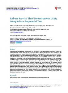
more highly thinned than other reports. IV. T HE B ENEFITS OF G OOD OVERLAP Even with extended inference, it is advantageous—for enhancing estimator accuracy—to encourage reports from different receivers to overlap as far as possible, in the sense that receivers should tend to report on the same probes. Note that, whether applying the extended inference algorithm from [11] to incomplete outcomes (with or without enhanced overlap), or restricting the original algorithm from [3] to complete outcomes, the resulting estimators are both consistent in that inferred link probabilities converge to their true values as the number of probes grows. However, the rate of convergence can be very different in each case, with larger rates leading to reduction in the variance of the corresponding estimates. We illustrate this with the following simple case. Consider inference on tree with r receivers, using n probes. If the complete outcomes were known for all probes, estimator variance would behave as n−1 for large n. This is basically a consequence of the Central Limit Theorem; see [3] for details in this context. Suppose now that only a proportion p of all receiver reports reached the inference engine, and in particular assume a simple model in which each report is independently present at the engine with probability p. In this model, there would be roughly npr probes on which the complete outcome would be known. The complete data estimator applied these reports alone would thus have variance that behaves as n−1 p−r for small p. This grows very rapidly with the number of receivers r. For the same model, estimator variance for the incomplete data algorithm of [11] can be shown to behave as n−1 p−2 for small p. This is because for small p, the dominant contribution to the estimator is provided by components from two receiver subtrees of the logical multicast tree; the number of probes which are received at both receivers of the subtree is roughly np2 . If successful transmissions overlapped perfectly across different receivers, then complete outcomes would be known for roughly np probes. Variance of the extended estimator would then behave as n−1 p−1 , i.e., smaller than when applied to independently present reports, and far smaller than that for the complete data algorithm on the same reports. In practice, overlap will not be perfect, so we expect estimator variance to be intermediate between n−1 p−1 and n−1 p−2 , depending on the degree of overlap. V. E XPERIMENTAL E VALUATION We evaluated our the effectiveness of our approach through experiments using the following criteria: (i) conformance of reporting bandwidth with the constraints of the RTCP standard; (ii) the effectiveness of coordinated thinning in promoting overlap; (iii) the effectiveness of report alignment in promoting overlap; and (iv) the accuracy of link loss rate inference, and the benefits in accuracy enjoyed by using coordinated thinning and report alignment. A. Experimental Configuration In order to facilitate larger scale evaluation, while avoiding the complexities of a fully-fledged instrumented deployment,
0.5
experiment: coordinated thinning theory: random thinning
0.45 0.4 0.35 proportion
we supplement the receiver’s and inference engine’s normal functions with a “simulation mode” to simulate the loss of probe and RTCP report packets. In this mode, all receivers and the inference engine execute on the same host. Instead of receiving actual probe packets from the network, each instance of mflect is driven by an event stream of simulated probe packets. These probe packets are generated according to the independent loss model of Section II, for a given topology and link transmission rates. Thinning and alignment take place in the usual execution of mflect , and RTCP packets are propagated in the network. However, this propagation is trivial since all instances of mflect are associated with the same physical interface of the host on which the simulation executes. The instances are distinguished by their SSRC, more than one of which can be associated with a given host. Each mflect is instrumented to keep a full trace of received probes that we use to determine the effectiveness of thinning and alignment in promoting overlap and inference accuracy. The inference engine also executes a simulation mode in which report packets are lost independently with a given probability. The simulation topology was a balanced binary tree with 16 receivers. The number of receivers was constrained by the number of copies of mflect that could comfortably run on a single host. We conducted two sets of 30 experiments. In the first set, link loss probabilities were chosen randomly between 1% and 10%, in the second they were chosen randomly between 0.1% and 1%. Although the first case represents probably the best that can be currently be achieved multicasting in the Internet, the second case represents a potential range of interest for applications that may utilize a more reliable multicast network in the future. We generated probe traffic with mgen, a packet generating program that we configured to send packets at a size and rate conformant with a GSM audio host, as described in Section IIIB. To compensate for the small number of receivers, we transmitted at ten times the allocated session bandwidth rate, using ten simulated audio sources. This has the effect of reducing the available reporting space in the outgoing RTCP packets, requiring the mflect hosts to thin their traces as if they were in a larger session. Probes were transmitted for 500 seconds, and records were kept on 6000 probes from each source.
0.3 0.25 0.2 0.15 0.1 0.05 0 0
2
4
6
8
10
12
14
16
successful reports Fig. 5. OVERLAP AND T HINNING : proportions of successful reports for coordinated thinning, and theoretical proportions for random thinning at same mean rate. With coordinated thinning, over 45% of probes have either all or no reports present, indicating good overlap.
Verification used tcpdump to track the size and timing of packets. Adding 20 octets to each UDP packet size to account for the IP header, we tracked the total number of octets transmitted by the mflect receivers over the course of an experimental run, the times of the first and last packets, and the total number of packets sent. This last value we verified against the mflect packet trace. In a typical trace, the mflects sent 58 packets, containing 83, 036 octets in the course of 981 seconds. Adjusting the duration by 59/58, we arrive at a bandwidth of 83.2 octets/second, which is conformant. This despite packet sizes ranging from 472 octets to 1, 512 octets. The largest packet sizes corresponded to the MTU of the UCL library. Viewing the mflect traces, we see that each packet contained reports upon each of the ten data sources, for a total of 580 reports. Half of these, 290, were without thinning; 240 employed a thinning factor of 2; and 50 employed a thinning factor of 4. These values are typical, though we have occasionally seen a thinning factor of 8. C. Overlap and Thinning
B. Conformance with RTCP Bandwidth Constraints We described the RTCP bandwidth constraints in Section IIIB. To recap, the data receivers in an RTP session are to collectively restrict themselves to 3.75% of the overall session bandwidth. In the case of a single-source audio session, they are allocated approximately 85 octets/second to share amongst themselves (and we maintained this limit, though we increased the number of sources). In extending RTCP to include MINC traces, our goal has been to work within these constraints, so that MINC inference can coexist in the same sessions as audio and video applications. Our RTCP extensions were built on top of the UCL RTP library, which implements the RTCP scaling mechanism. We tested to verify that inclusion of MINC reports, some very large, and varying in size over time, does not stress this mechanism in such a way as to violate the constraints.
Figure 5 shows the experimental proportions of successful loss reports from 16 receivers, compared with the theoretical proportions with random thinning at the same mean rate. Recall that overlap is promoted when the distribution is more concentrated towards the extremes (0 and 16), for then receivers tend to report (or omit to report) on the same probes. For random thinning, the theoretical proportions are maximal near the mean rate. With coordinated thinning, over 45% of the probes have reports for either no or all probes, indicating that overlap is significantly better than would be obtained with random thinning. D. Overlap and Alignment We now demonstrate how alignment of report packet boundaries can promote overlap in the presence of RTCP report loss. Consider the number of reports on a given probe that are receivable, by which we mean the number of reports that, if not
0.8
probe loss 1%-10% 0.1%-1%
with alignment without alignment
0.7
proportion
0.6 0.5
error factors α bcomp α b α bran 1.05 1.08 1.11 1.20 1.27 1.64
TABLE I I NFERENCE ACCURACY AND T HINNING : TWO - SIDED QUARTILE - WEIGHTED MEDIAN OF ERROR FACTORS. S UBSTANTIAL
0.4 0.3
REDUCTION IN ERROR IS OBTAINED BY USE OF COORDINATED AS OPPOSED TO RANDOM THINNING , PARTICULARLY WITH LOW LOSS RATES.
0.2 0.1 0 0
2
4
6
8
10
12
14
16
probe reports receivable Fig. 6. OVERLAP AND A LIGNMENT: proportions of probe reports receivable after RTCP report loss at 10%. Overlap enhanced (i.e. distribution more concentrated at extremes) with alignment.
thinned out by mflect, could be successfully transmitted to the inference engine. At our option, alignment of RTCP report boundaries can be turned off on mflect for evaluation purposes. Figure 6 shows the experimental proportions of probe reports in a regime of 10% average RTCP report loss. Without alignment, the number of receivable reports is clustered around a single peak near 11. With alignment, the peak becomes separated into two groups of higher and lower numbers of reports, indicating better overlap. E. Accuracy of Inference In order to demonstrate the accuracy of inference, and how it is promoted by overlap, we compare the following sets of quantities: (i) the model link transmission rates α; (ii) the inferred link transmission rates α bcomp based on complete data as seen at the receivers; (iii) the inferred link transmission rates α b based on reports reaching the inference engine, as subject to both thinning and RTCP packet loss; and (iv) the inferred link transmission rate α bran based on reports on the inference engine, but subject to random rather than coordinated thinning. Given a threshold loss rate ε > 0, we compare model and inferred transmission rates, αk and α bk for a given link k through the error factor: max{1 − αk , ε} Fε (αk , α bk ) = exp log max{1 − α bk , ε}
(2)
The error factor is the factor by which the corresponding loss rates differ, where each is taken to be no less than ε. Thus we can think of an error of p% as represented by an error factor of 1 + p/100. In the experiments here, we have chosen ε = 10−4 , one order of magnitude lower than the lowest link loss rate used in the simulation of probe loss. Suppose we have a set of pairs of model and inferred link transmission rates gathered over all links during multiple simulations. We summarize the set of pairwise error factors through a robust estimate of the center of their distribution, namely the
report loss 5% 10% 50%
α b error factors 1.08 1.09 1.34
TABLE II I NFERENCE ACCURACY AND R EPORT L OSS : ERROR FACTORS , AS FUNCTION OF REPORT LOSS RATE . (L INK LOSS RATES FROM 1% TO 10%)
two-sided quantile weighted median: Q0.25 + 2Q0.5 + Q0.75 , 4
(3)
where Qp is the pth -quantile of the the error factors. Table I shows two-sided quartile-weighted median of error factors in the two loss rate regimes. The first column ( α bcomp ) represents the best accuracy available by MINC inference using all receiver data. For the higher loss regime, the additional error attributable to random thinning (third column, α bran ) is 1.11 − 1.05 = 6%. This is halved (to 1.08 − 1.05 = 3%) by coordinated thinning (second column, α b). The benefits of coordinated thinning are even more striking in the low loss regime. Table II shows the growth in error factors as a function of the rate of loss of RTCP packets. Observe that errors are quite insensitive to moderate losses, increasing only from 8% to 9% as the loss rate increases from zero to 10%. VI. C ONCLUSIONS AND F URTHER W ORK This paper has defined and implemented an architecture in which a scalable and informal infrastructure for multicast endto-end measurement and reporting is embedded in a transport protocol, RTP, using application hosts and measurement endpoints. This approach has a number of benefits: scope (any multicast group member can act as a source or receiver of probes, or as an inference engine), scalability (regular traffic constitutes the probes, and RTCP manages the bandwidth of report traffic), and deployability (it can be incorporated into multicast applications). Because we intended loss reports as input for MINC inference, we took steps in our implementation to enhance accuracy in the face of thinning (i.e. the deliberate omission of probe reports in order to fulfill constraints on RTCP reporting bandwidth) and RTCP report loss. These steps promoted the overlap of reports from different receivers through distributed coordination
of probe report thinning and RTCP report alignment. The extended MINC estimator is tolerant of missing data, but is more accurate when reports overlap, i.e., when receivers report more on the same set of probes. Our experimental work demonstrated the benefits for accuracy of these approaches: estimation error arising from thinning and report loss was halved (for link loss rates in the 1% to 10% range) and strongly reduced for lower loss rates (down to 0.1%). Estimation accuracy of 1 part in 10 was obtained for the higher range of link loss, with better than 1 part in 3 for the lower range of link loss. This was from probes generated at the rate of regular audio source over a duration of a few hundred seconds. Further work in progress is to evaluate the approach in a real network. To this end, we are currently deploying our software on the NIMI infrastructure. This will allow us to assess the impact on inference accuracy of actual patterns of probe and report loss, rather than the idealizations embodied in our statistical model. These experiments can take advantage of the scheduling and trace collection functions of NIMI. Accuracy will be assessed by comparing link loss rate estimates from the incomplete data, with those obtained using full traces collected in the NIMI hosts. The accuracy of the latter has been established in [4]. Future work will be to integrate the software, along with a topology inference capability, into a real-time multicast application. This could be used to provide a real-time readout of network-wide performance, either for users, or for use by those applications. ACKNOWLEDGMENTS We thank Mark Handley for the suggestion to use RTCP for reporting. Members of the UCL Network and Multimedia Research Group, whose RTP library we built upon, and in particular Colin Perkins, who extended its API. Steve Casner, and again Colin Perkins, of the IETF AVT working group, for their suggestions. Kevin Almeroth and Kamil Sarac, for working with us in defining packet standards. Bill Fenner for extensive consultation on mtrace and multicast connectivity. Vern Paxson for zing, and he and Andrew K. Adams for the NIMI testbed, and considerable help with its use. Tian Bu for the mint inference engine, and Wei Wei for its missing-data version, eminfer. Sue Moon for mgen. Nicolas Oury for his compression work. May Chim for her programming contributions. Don Towsley and Jim Kurose for numerous constructive suggestions. Joseph Horowitz and Francesco Lo Presti, our collaborators on the MINC project, for their continued advice and support. MINC
[5]
[6] [7]
[8]
[9] [10]
[11]
[12]
[13]
[14] [15]
[16] [17]
[18]
[19]
[20] [21] [22]
[23]
[24]
[25] [26]
[27]
R EFERENCES [1]
[2]
[3]
[4]
A. Adams, T. Bu, R. C´aceres, N.G. Duffield, T. Friedman, J. Horowitz, F. Lo Presti, S.B. Moon, V. Paxson, D. Towsley, “The Use of End-to-End Multicast Measurements for Characterizing Internal Network Behavior”, IEEE Communications Magazine, May 2000. Jean-Chrysostome Bolot, “End-to-end packet delay and loss behavior in the Internet”, in Proc. of ACM SIGCOMM’93 (New York), ACM, 1993, pp. 289–298. R. C´aceres, N.G. Duffield, J.Horowitz and D. Towsley, “Multicast-Based Inference of Network Internal Loss Characteristics”, IEEE Trans. on Information Theory, vol. 45, pp. 2462-2480, 1999. R. C´aceres, N.G. Duffield, S. B. Moon, and D. Towsley, “Inference of
[28]
[29] [30]
[31]
Internal Loss Rates in the Mbone”, in Proc. IEEE/ISOC Global Internet ’99, December 1999. J. Cao, D. Davis, S. Vander Wiel, B. Yu, “Time-Varying Network Tomography: Router Link Data”, J. Amer. Statist. Assoc., vol. 95, pp. 1063-1075, 2000. R. Carter, M. Crovella, “Measuring bottleneck link-speed in packetswitched networks”, Performance Evaluation, 27&28, 1996. M. Coates, R. Nowak. “Network loss inference using unicast end-to-end measurement”, in Proc. ITC Conf. IP Traffic, Modeling and Management, Sept. 2000. A.P. Dempster, N.M. Laird, D.B. Rubin, “Maximum likelihood from incomplete data via the EM algorithm (with discussion)”, J. Roy. Stat. Soc. Ser., vol. 39, pp. 1–38, 1977. A.B. Downey. “Using pathchar to estimate Internet link characteristics”, in Proc. SIGCOMM’99, Sept. 1999. N.G. Duffield, J. Horowitz, F. Lo Presti, D. Towsley, “Multicast Topology Inference from Measured End-to-End Loss”, IEEE Trans. on Information Theory, vol. 48, pp. 26–45, 2002. N.G. Duffield, J. Horowitz, D. Towsley, W. Wei, T. Friedman, “Multicastbased loss inference with missing data”, IEEE Journal on Selected Areas in Communications, 2002, to appear. N.G. Duffield and F. Lo Presti, “Multicast Inference of Packet Delay Variance at Interior Network Links”, in Proc. IEEE Infocom 2000, Tel Aviv, March 2000. N.G. Duffield, F. Lo Presti, V. Paxson, D. Towsley, “Inferring link loss using striped unicast probes,” in Proc. IEEE Infocom 2001, Anchorage, Alaska, April 22-26, 2001. T. Friedman, R. C´aceres, K. Almeroth, K. Sarac, “RTCP Reporting Extensions”, work in progress. M. Handley and C. Perkins, “Guidelines for Writers of RTP Payload Format Specifications”, IETF RFC 2736 (Best Current Practice BCP 36), December 1999. R.J.A. Little and D.B. Rubin, Statistical Analysis with Missing Data, Wiley, New York, 1987 F. Lo Presti, N.G. Duffield, J.Horowitz and D. Towsley, “Multicast-Based Inference of Network-Internal Delay Distributions”, submitted for publication. N. Oury, and T. Friedman, “Compression des traces de perte de paquets multicasts sur Internet”, Proc. of Journ´ees Doctorales Informatique et R´eseaux - JDIR’2000, Paris, November 2000. V. Paxson, J. Mahdavi, A. Adams, M. Mathis, “An Architecture for LargeScale Internet Measurement,” IEEE Communications, Vol. 36, No. 8, pp. 48–54, August 1998. V. Paxson, “End-to-end Internet packet dynamics”, IEEE/ACM Transactions on Networking 7 (1999), no. 3, 277–292. V. Jacobson, “Pathchar - A Tool to Infer Characteristics of Internet paths”. For more information see ftp://ftp.ee.lbl.gov/pathchar S. Ratnasamy & S. McCanne, “Inference of Multicast Routing Tree Topologies and Bottleneck Bandwidths using End-to-end Measurements”, in Proc. IEEE Infocom’99, New York, March 1999 S. Ratnasamy & S. McCanne, “Scaling End-to-end Multicast Transports with a topologically sensitive Group Formation Protocol”, in Proc. IEEE International Conference of Network Protocols ICNP ’99 UCL Network and Multimedia Research Group, Robust Audio Tool. For information see: http://wwwmice.cs.ucl.ac.uk/multimedia/software/rat/index.html. H. Schulzrinne, S. Casner, R. Frederick, V. Jacobson, “RTP: A Transport Protocol for Real-Time Applications”, IETF RFC 1889, January 1996. H. Schulzrinne and S. Casner, “RTP Profile for Audio and Video Conferences with Minimal Control”, work in progress, November 2001. For further information see: http://www.ietf.org/html.charters/avt-charter.html C. Tebaldi and M. West, “Bayesian Inference on Network Traffic Using Link Count Data”, J. Amer. Statist. Assoc., vol. 93, pp. 557–572, 1998. Y. Tsang, M. Coates and R. Nowak, Passive Unicast Network Tomography based on TCP Monitoring, Rice University, ECE Department Technical Report TR-0005, November 2000. Y. Vardi, “Network Tomography: estimating source-destination traffic intensities from link data”, J. Am. Statist. Assoc., 91: 365–377, 1996. Maya Yajnik, Sue Moon, Jim Kurose, and Don Towsley, “Measurement and modelling of the temporal dependence in packet loss”, in Proc. of IEEE INFOCOM 99, New York, March 21-25, 1999. A.-G. P. Ziotopoulos, A. O. Hero, K.M. Wasserman, “Estimation of network link loss rates via chaining in multicast trees”, in Proc. of IEEE Int. Conf. on Acoust. Speech and Sig. Proc., Salt Lake City UT May 2001.