Asmaa Q. Shareef et al, International Journal of Computer Science and Mobile Computing, Vol.3 Issue.6, June- 2014, pg. 286-296
Available Online at www.ijcsmc.com
International Journal of Computer Science and Mobile Computing A Monthly Journal of Computer Science and Information Technology
ISSN 2320–088X IJCSMC, Vol. 3, Issue. 6, June 2014, pg.286 – 296 RESEARCH ARTICLE
Improved Accuracy Distribution Localization in Wireless Sensor Networks Asmaa Q. Shareef 1, Maad M. Mijwel 2 ¹,2College of Science, University of Baghdad, Iraq 1
[email protected], 2
[email protected]
Abstract— Localization system is important when there is an uncertainty of the exact location of some fixed or mobile devices. In this paper, the problem of localization system to estimate the position of randomly deployed nodes of a wireless sensor network (WSN) is addressed, a propose algorithm named Improved Accuracy Distribution localization for wireless sensor networks (IADLoc) is issued, it is used to minimize the error rate of localization without any additional hardware cost and minimum energy consumption and also is decentralized implementation. The IADLoc is a range free and range based localization algorithm that uses both type of antenna (directional and omni-directional), it allows sensors determine their location based on the region of intersection (ROI) when the beacon nodes send the information to the sink node and the latter sends this information to the sensors relying on the antenna. Keywords— Improved Accuracy Distribution Localization, antenna: directional and omni-directional; wireless sensor network, beacon nodes I. INTRODUCTION A wireless sensor network (WSN) is a network composed of a large number of sensor nodes, which are deployed in the monitoring field. With the rapid development of WSNs, providing development tools such as simulation environment before deploying real nodes in physical environments is getting more important. A well simulated environment [1] can help developers to build their prototype models to know the interactions and the behaviour of each node. In addition, most of WSN applications deploy large number of nodes in the simulated environment [2]. Localization is one of technologies in WSNs, it is used to estimate the position or coordinates of sensor nodes and sink nodes, which also called beacon nodes (locator or anchor) [3]. The localization algorithms can be divided into two categories: range-based algorithms and range-free algorithms. The ranged-based algorithms need to measure absolute point-to-point distance estimates or angle estimates in order to calculate the locations of unknown nodes. Range-free algorithms use the information of anchor nodes or the connectivity of WSN to estimate a rough coordinate as the actual one of unknown nodes [4].
© 2014, IJCSMC All Rights Reserved
286
Asmaa Q. Shareef et al, International Journal of Computer Science and Mobile Computing, Vol.3 Issue.6, June- 2014, pg. 286-296
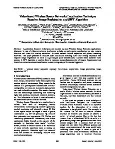
II. PROBLEM STATEMENT The Sensor Network Localization Problem (SNLP) is a big challenge optimization problem, which has focused by many researchers during the last two decades. The problem in research can summarize as follows: how to determine the location information of all or a subset of sensor nodes on a basis that lose target in the tracking and monitoring applications due to incorrect location identification which may give incorrect results. The sensors may not cover all the area to be monitored, nor may change movement path, as a result may cause sensors to leave the monitoring area. Deployment the coordinates of the sensors within the area of the intersection takes high execution time, whenever the sensing area increase, the execution time also increases. If any sensors in the network for any reason stop working, this may affect on network tasks. Through this paper, two types of antennas have been used, they are: Directional antenna that focuses signal propagation in one or several specific directions, and often used in external networks. Omni-directional antenna that sends its signal in all directions consistently and often used in internal networks. The use of mobile sensor nodes in localization has several advantageous, because it provides tracks on object movement along their corresponding trajectories. Despite of a mobile sensor node is expensive than a static sensor node, but compared to its efficiency, a set of small number of mobile sensors for localization was selected. III. LOCALIZATION IN WSN Localization is the process by which sensor nodes determine their location. In simple terms, localization is a mechanism for discovering spatial relationships between objects [5]. Localization system among sensor nodes is a fundamental issue for many applications of WSNs. Because sensor networks may be deployed in inaccessible terrains or disaster relief operations, the position of sensor nodes may not be predetermined [6]. Thus, a localization system is required in order to provide position information to the nodes [7]. Localization systems can be divided into three components as shown in Fig. 1.
Fig.1 Localization system components
Distance/angle estimation: This component is responsible for estimating information about the distances and/or angles between two nodes. This information will be used by the other components of the localization system. Position computation: This component is responsible for computing a node’s position based on available information concerning distances/ angles and positions of reference nodes. Localization algorithm: This is the main component of a localization system. It determines how the available information will be manipulated in order to allow most or all of the nodes of a WSN to estimate their positions. [8].
IV. IADLOC ALGORITHM The IADLoc algorithm work is based on the signals coming from the beacon node and the receipt of these signals by sink node (base station) and sends to the sensor and applies to both static and mobile motion. Sensor collects the information about the target and sends to the sink. IADLoc is a distributed © 2014, IJCSMC All Rights Reserved
287
Asmaa Q. Shareef et al, International Journal of Computer Science and Mobile Computing, Vol.3 Issue.6, June- 2014, pg. 286-296
nodes and its range free and also range-based algorithm; the advantage of IADLoc is minimizing the error rate of localization without any additional hardware cost and minimum energy consumption and also decentralized implementation. Fig. 2 shown the sample of IADLoc with one way.
Fig.2 Sample of IADLoc with one way
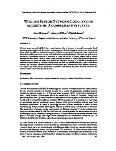
This algorithm is the integration of the three other algorithms; at first restricted area-based localization algorithm [4], which is free range and omni-directional antenna, the function of this algorithm utilizes all the perpendicular bisectors of the line which connects each pair of sink nodes and give the coordinates for sensor nodes. The second algorithm is power tuning anchors [9] for mobile sensor is free range and omni-directional antenna; the function of this algorithm localizes the position of sensors on the received power levels transmitted by the neighboring sink nodes. That all the sinks can be able to their transmission power and transmit beacon signals at different power levels starting from maximum to minimum received by sensors. The third algorithm high-resolution robust localization [10] that is free range and directional antenna, the function of this algorithm sensor determines their location based on the intersection of the areas covered by the beacons transmitted by reference points. Beacon Nodes (BN) are nodes deploy in the area have target are a necessary in the localizing a network. The main function of BN is to send information to the sink (base station) about the target in the area. An assumption of group of sensors and the target inserted in the area the BN from the moment enter the target send sends directly information to the base station and turn send to the sensor as show in Fig. 3.
Fig.3 Work of the beacon node
The IADLoc algorithm depends on region of intersection ( ) where the intersections between the signals of sink nodes the intersection between sinks and depended at the same sensor and same communication that's where are sink nodes both send their own signal by using antenna in the same area where there are sensors and the receipt of information for tracking and monitoring the target in the . In IADLoc each sensor in the area determines their location (sensors do not interact to determine their location) based at the beacon information transmitted by sink nodes with high accuracy. Each sink transmits beacon information by using an antenna and beacon containing the sink coordinates and angle of the antenna boundary line with respect to a common global axis. An example is shown in Fig. 4 where is intersected with through the same sensors , where the beacon node send the information to the sink nodes after that the sensors received and send the information to the while the is region communication for the sink nodes.
© 2014, IJCSMC All Rights Reserved
288
Asmaa Q. Shareef et al, International Journal of Computer Science and Mobile Computing, Vol.3 Issue.6, June- 2014, pg. 286-296
Fig.4 Sink1 intersections with sink2 at same sensor and communication using directional antennas
In network deployment, we have set of sensors without known location and randomly distributed with density in the area . Also assume nodes know the location and orientation called sinks randomly |
|
distributed with density , . To distributed random of sink nodes with density can be modeled as a spatial homogeneous Poisson point process. Sensors distributed random can be as modeled | |
as random sampling of the area with density . The with range and distributed sensors hears exactly equation (1) (|
|
)
(
)
(
denoted to the sink node heard by sensors sinks to given by the Poisson distribution by
)
( )
From using equation (1), used to compute the probability for every sensor hears at least sinks. The random distributed sensor node in the number of sink nodes heard after received the information from beacon nodes by each sensor: (| | ) (| | )| | ( ) (| | ) (| | )| | ( ( ) ( ) (| | ) ( ( )| | ∑ ( ) The sensors collects information coming from the sinks with it coordinates ( ) and the coordinates for all sinks ( ) with radius centered at ( ). * ‖ ‖ ( )+ Where | | ( ) The sensors deployment randomly in the area and search its place by finding sinks heard coordinates where it is minimum coordinates and it is maximum coordinates. To distribute sensor nodes (static or mobile) in boundary the area where is the sensors distributed right vertical boundary, is the sensors distributed left vertical boundary, and is the sensors distributed left horizontal boundary. To deploy beacon nodes (BN) randomly and send information by victor to sink ∑→ Where
’ the initial estimate location of the sensor node
( ) and → is a vector.
a-
IADLoc algorithm with directional antenna A directional antenna also called (beam antenna) is an antenna which is used to send greater power of the signal in one or more directions and it is controlled by base station. The direction antenna focuses its energy only in a certain direction and reduces interference from the surrounding environment to increase the accuracy of the translation of the sensor within the . The IADLoc algorithm use directional antenna assisted to reduce error in localization WSNs, high cost, sensor distribution and topology control. The sink node (base station) used to transmit the signal coming from the beacon node to the sensors (static or mobile) as shown in Fig. (3).
© 2014, IJCSMC All Rights Reserved
289
Asmaa Q. Shareef et al, International Journal of Computer Science and Mobile Computing, Vol.3 Issue.6, June- 2014, pg. 286-296
The sinks are equipped with directional antenna in the antenna model used to broadcast information also have radiated power with a directive gain . Directive gain can be defined as which combines the antennas directivity and electrical efficiency. Also in antenna model the sensors are equipped with Omni-directional having sensors to sensors communication range . The sinks transmission range is started from minimum value zero to maximum value and the sinks can change their orientation or rotating their directional antennas. The sinks transmits the signal to a specific destination with directed gain ( ) ( ) ( ) ∫ ) as defined by power transmission of Where the , are the angles and is directed gain with ( signals in a certain direction and is denoted the orientation of the directional antenna. also depends on the power of broadcast . ( ) ( ) ( ) The
is a function of angles ( ) ( ) ∫ According to (3.5),to calculated directional antenna by
( )
(
)
Where is constant and is transmission range of the sink. The region of intersection ( )is the intersection of signals between two or more sink nodes to be reduce range of sink nodes by equation (11) ( ) () ( ) ( ) ⁄ . Where is total number of distinct communication ranges the sinks reduce the range by The antenna can change direction orientation and intersection with other antennas by the equation (12) as shown in Fig. 5.
Fig.5 The
( )
{
(
)
by rotation antenna is reduce communication range by angle
(
)
}
(
)
Where , are angels of sinks and is the number of antenna, is the total number of antenna orientation. In the the sensors are only considered for position estimation and calculation of average localization error. When the beacon moves from old ( ) to new ( ) the sensors receive only beacon message from sinks and does not received message from its neighbouring sensors. The sensors determine estimated position from old ( ) to new ( ) based on beacon information transmitted from a set of sinks by single beam directional antennas and the sinks is fixed positions. Estimation position error of ) and ( ) where coordinates of sensor between old and new coordinates ( and divided by the number of nodes. ∑ √( ) ( ) ( ) Thus the sensors know the location and new coordinates. To calculate average localization error by ⁄
© 2014, IJCSMC All Rights Reserved
290
(
)
Asmaa Q. Shareef et al, International Journal of Computer Science and Mobile Computing, Vol.3 Issue.6, June- 2014, pg. 286-296
IADLoc algorithm shows the high resolution robust localization for WSNs (HiRloc) with restricted area based algorithm (RAL) and using directional antenna. b- IADLoc algorithm with Omni-directional antenna An omni-directional antenna is a class of antenna that radiates energy radio waves uniformly in all directions are used to create hot spots by transmitting a signal over a wide area in all directions or receiving signals in all directions at the site of transmission is unknown or near it is rotated . In the localization WSNs the sink nodes need to send the information to the sensor for long distance by using omni-directional antenna the greater the distance increased level of broadcasting and. In the Fig. 6 shows the sink node send packet with different power level for all sensors (mobile or static) by the power level for long distance
Fig.6 The sink node send packet with deferent power level
The IADLoc algorithm uses omni-directional antenna assisted to minimize redundancy in WSNs add to that its ability to broadcast in all directions and exploited the directional omni-directional antenna outfitted on a sink node to reduce redundancy and network at the same time is kept touch sensor nodes with the sink node. The IADLoc algorithm depended at the intersection all circles benefits of this decrease hardware cost where any level of the other sink node depends on the same sensor .as shown in the Fig. 7 intersection between three sink nodes with two power level.
Fig.7 The intersection between three sinks with same sensor
The beacon nodes send the information to all sinks where the is intersection with and is intersection with and is intersection with with same sensor .the sink nodes broadcasts beacon signals with their maximum power level to the sensor nodes to position identification. Those selected sinks then reduce their power levels and retransmit the beacons information to other or same sensors. In the IADLoc algorithm need to find all circles intersecting with each other depended at three equations The equation ( ) Then one circle is inside other and no solution. ( || ||) ( ) ( ) The equation ( ) then the circles are separate and no solution. ||) ( ) ( || ( ) Only this equation (3.23) comes up with intersecting the two circles at two different points. ( || ||) ( ) ( ) Increase the number of power level for sink nodes by the equation (18) © 2014, IJCSMC All Rights Reserved
291
Asmaa Q. Shareef et al, International Journal of Computer Science and Mobile Computing, Vol.3 Issue.6, June- 2014, pg. 286-296
,
,
Where Fig. 6.
-
Counter of power level and
( ) is number of power level as shown in the
is the circle,
To calculate the distance and intersection points between all circle. Further calculations result in identifying the intersection points. ( )
(
)
Solve for by substituting ( ) (
) ( ( ( (
(
from the equation (18)into the equation
)
)
( (
)
(
)
(
)
(
)
(
)
(
)
(
)
(
)
comes up with
) (
)
) ) )
Now all circles are intersection by same sensor all by power level this leads to that any sink node have information from the sensor and thus achieves Decreasing hardware cost. Estimation position error of ) and ( ) where coordinates of sensor between old and new coordinates ( and divided by the number of nodes. ∑ √( ) ( ) ( )
Thus the sensors know the location and new coordinates. To calculate average localization error by ⁄
(
)
V. PERFORMANCE EVALUATION In the WSNs localization simulator, the sink nodes are deploy with coordinates and antennas and are a fixed place. the strategy for sink node deployment four axes, first the grid is randomly deployed, second the grid with 8 sinks, third the grid with 6 sinks, fourth the grid with 5 sink and the number of sink nodes are intersection from 2 to 8 sinks with type of antenna (directional or omni-directional) and it's radio rage with 250 m and beam width 45 . Table (1) shows the summarized of the parameter WSNs localization simulator.
© 2014, IJCSMC All Rights Reserved
292
Asmaa Q. Shareef et al, International Journal of Computer Science and Mobile Computing, Vol.3 Issue.6, June- 2014, pg. 286-296
TABLE I The parameter WSNs localization simulator
Parameter
Value
Sensor filed
500m x 500m
Number of sink node
8 or 6 or 5
Sink radio range
250 m
Sink beam width
45
Number of beacon nodes
50
beacon radio range
40 m
Sensors node
200
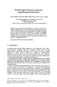
To study the behaviour of IADLoc algorithm and accuracy evaluated with respect to each testing section. Fig.10, 11 and 12 show the IADLoc algorithm with directional antenna and accuracy comparison results for it. Fig. 10 shows that IADLoc algorithm results with 8 sink nodes without change antenna or with change it and 2, 3 sinks are intersection with each. 35 30 25 20 15 10 5 0
no. of sensors execution time IADLoc with 8 IADLoc with 8 sink 2 sink sink 2 sink intersection intersection without change with change anntena anntena
IADLoc with 8 sink 3 sink intersection with change anntena
average localization error
Fig. 10 IADLoc algorithms with 8 sink nodes
Fig. 11 shows that IADLoc algorithm results with 6 sink nodes without change antenna or with change it and 2, 3 sinks are intersection with each. 35 30 25 20 15 10 5 0
no. of senors execution time IADLoc with 6 IADLoc with 6 sinks 2 sink sinks 2 sink intersection intersection without change with change antenna antenna
IADLoc with 6 sinks 3 sink intersection with change antenna
average localization error
Fig.11 IADLoc algorithms with 6 sink nodes
Fig. 12 shows that IADLoc algorithm results with 5 sink nodes without change antenna or with change it and 2, 3 sinks are intersection with each.
© 2014, IJCSMC All Rights Reserved
293
Asmaa Q. Shareef et al, International Journal of Computer Science and Mobile Computing, Vol.3 Issue.6, June- 2014, pg. 286-296
35 30 25 20 15 10 5 0
no. of sensors execution time average localization error IADLoc with 5 IADLoc with 5 sinks 2 sink sinks 2 sink intersection intersection without change with change antenna antenna
IADLoc with 5 sinks 3 sink intersection with change antenna
Fig. 12 IADLoc algorithms with 5 sink nodes
Fig. 13, 14 and 15 show the IADLoc algorithm with omni-directional antenna and accuracy comparison results for it. Fig. 13 shows that IADLoc algorithm results with 8 sink nodes without change antenna or with change it and 2, 3 sinks are intersection with each. 60 50 40 30 20 10 0
no. of sensors execution time IADLoc with 8 sinks 2 IADLoc with 8 sinks 2 sink intersection sink intersection with without change antenna change antenna
average localization error
Fig. 13 IADLoc algorithms with 8 sink nodes
Fig. 14 shows that IADLoc algorithm results with 6 sink nodes without change antenna or with change it and 2, 3 sinks are intersection with each. 50 40 30
no. of sensors
20
execution time
10
average localization error
0 IADLoc with 8 sinks 2 sink intersection without change antenna
IADLoc with 8 sinks 2 sink intersection with change antenna Fig. 14 IADLoc algorithms with 6 sink nodes
Fig. 15 shows that IADLoc algorithm results with 5 sink nodes without change antenna or with change it and 2, 3 sinks are intersection with each.
© 2014, IJCSMC All Rights Reserved
294
Asmaa Q. Shareef et al, International Journal of Computer Science and Mobile Computing, Vol.3 Issue.6, June- 2014, pg. 286-296
45 40 35 30 25 20 15 10 5 0
no. of sensors execution time average localization error IADLoc with 8 sinks 2 sink intersection without change antenna
IADLoc with 8 sinks 2 sink intersection with change antenna Fig. 15 IADLoc algorithms with 6 sink nodes
VI. CONCLUSIONS We showed that IADLoc algorithm accuracy distribution need less time to find the coordinates or location for sensor nodes (static and mobile) with low average localization error, requiring fewer hardware resources and low power consumption. It applied to both types of antenna (directional and omnidirectional) with an increased level of broadcasting and also been used with both types of movement sensors (static or mobile) with IADLoc algorithm terms of use static sensor with directional antenna where mobile sensor used with omni-directional antenna reverse previous algorithms that were used one type of antennas with a specific level of broadcast and used one type of movement of sensors. The IADLocs increases the level of the broadcast of beacon nodes to cover a larger area in order to send the information to the sink nodes. In the IADLoc algorithm, the sink nodes transmit the beacon signals at different power levels so that the sensor nodes can obtain the possible location area according to the information received from sink nodes. Omni-directional antenna is better than directional antenna because they have the ability to send information in all directions reverse directional antenna to send a single destination. All signals of sink nodes are intersected with each where this area is named region of intersection, where all sink nodes can send and receive the information to the same sensors node. ACKNOWLEDGMENTS Our thanks to Referee who read our paper and to the experts who contributed towards development of the template, also our thanks to the Editorial Support Team, International Journal of Computer Science and Mobile Computing.
REFERENCES [1] A.Q. Shareef, M.M. Mijwel, "A Comparative Study by using Wireless Sensor Network Localization Simulator", The Second International Women conference, Ministry of Science and Technology, 2014. [2] A.M. Naguib. (2011) [Online]. Available:http://www.codeproject.com/Articles/225536/Wirless-Sensor-NetworkLocalization-Simulator-v. [3] H. K. Olafsen,” Wireless Sensor Network Localization Strategies,” University of Oslo Department of Informatics, Master thesis, 13 May 2007 [4] C.Wang, K.Liu, N. Xiao: A Range Free Localization Algorithm Based on Restricted-Area for Wireless Sensor Networks, 3rd International Multi-Conference on Computing in the Global Information Technology IEEE 2008, Pages 97-101. [5] A. Srinivasan, J. Wu,” A Survey on Secure Localization in Wireless Sensor Networks” Florida Atlantic University, Boca Raton, FL, USA © 2014, IJCSMC All Rights Reserved
295
Asmaa Q. Shareef et al, International Journal of Computer Science and Mobile Computing, Vol.3 Issue.6, June- 2014, pg. 286-296
[6] I. F. Akyildiz et al., “Wireless Sensor Networks: A Survey,” Comp. Networks, vol. 38, no. 04, Mar. 2002, pp. 393–422. [7] R.Arthi, K.Murugan,” Location Estimation of Sensor Nodes Using Learning Movement Patterns,” IEEE Computer Society, vol.10, pp.4244- 5974, Apr.2010. [8] A. Boukerche, H. A. B. F. Oliveira, E. F. Nakamura, A. A. F. Loureiro,” Localization Systems for Wireless Sensor Networks,” IEEE Wireless Communications, vol.07, pp. 1536-1284, Dec.2007. [9] S.Jabbar, M.Z.Aziz, A.A Minhas, D. Hussain: A Novel Power Tunning Anchors Localization Algorithm for Mobile Wireless Sensor Nodes, 2010 10th IEE International Conference on Computer and Information Technology (CIT 2010), Pages 2241-2446. [10] L.Lazos and R.Poovendran: High-resolution Robust Localization for Wireless Sensor Networks, CTA forms ARL, DAAD19-01-2-2011; ONR award, N00014-04-1-0479; ARO grant, W911NF-05-1-0491.
© 2014, IJCSMC All Rights Reserved
296