Improved quadtree image segmentation approach to region information Z. F. Muhsin1, A. Rehman*2, A. Altameem3, T. Saba4 and M. Uddin5 Images are full of information and most often, little information is desired for subsequent processing. Hence, region of interest has key importance in image processing. Quadtree image segmentation has been widely used in many image processing applications to locate the region of interest for further processing. There are also variable block-size image coding techniques to effectively reduce the number of transmitted parts. This paper presents quadtree partition technique as a pre-processing step in image processing to determine what part should be more heterogeneous than the others. It also introduces an idea to solve the problem of squared images. Finally, proposed approach is implemented and analysed. The simulation of the Matlab code of the quadtree is represented by all algorithms and the figures. Thus, achieved results are promising in the state of the art. Keywords: Quadtree, Image segmentation, Image compressing, Information acquisition, Region of interest (ROI), Image visualisation
Introduction The quadtree (QT) decomposition or partitioning is widely used in the digital image processing applications. It has also been found that manipulations and calculations operations done upon an image by QT prove to be efficient. The QT segments the image into homogenous and heterogeneous parts to allocate fewer bits to homogenous regions and more bits to those regions that contain additional detail and sharper features, which means that specific information embedded in the images, is of high worth than the rest.1,2 Hence, this information is required to extract its background. The QT method scans the bitmap area by area to identify matching pixels (area has homogenous features).3,4 The QT achieves a structure with a variable block-size decomposition of an image, where the movement to a smaller block size represents fine details more accurately and it can be carried out according to the outcome of any homogeneity test criteria. The weakness of the fixed size partitioning lies in the fact that there are regions which are difficult to cover well. There may be homogenous image regions, which could be sufficiently represented by using large blocks, while in the high 1
Department of Computer Science, Isra University, Amman, Jordon MIS Department, College of Business Administration, Salman bin Abdul Aziz University, Al Kharj-Riyadh, Saudi Arabia 3 College of Applied Studies and Community Services, King Saud University, Riyadh, Saudi Arabia 4 College of Engineering and Computer Sciences, Salman bin Abdul Aziz University, Al Kharj-Riyadh, Saudi Arabia 5 Kulliah of Information and Communication Technology, International Islamic University, Malaysia, Kuala Lumpur, Malaysia; Faculty of Computing, Asia Pacific University, Kuala Lumpur, Malaysia 2
*Corresponding author: Amjad Rehman, MIS Department, College of Business Administration, Salman bin Abdul Aziz University, Al KharjRiyadh, Saudi Arabia; email:
[email protected]
56
ß 2014 RPS Received 26 March 2013; accepted 26 September 2013 DOI 10.1179/1743131X13Y.0000000063
contrast regions, smaller blocks might be fruitful to achieve desired image quality.5,6,13 In the QT, a parent node denotes image and its four quadrants are symbolised by four child nodes. The QT comprises of a number of internal nodes and a number of leaf nodes. Leaf nodes correspond to the homogenous/uniform quadrants (one where all the pixels have the same colour), whereas internal nodes correspond to heterogeneous/no uniform quadrants (do not have the same colour in all their pixels; it is an interior node). The size of the QT is directly proportional to the complexity of the images: the more complex the image, the greater the QT size and vice versa.7,14 During segmentation, the necessary parameters are computed for an image block; the parameters values are compared with the thresholds, the resulting homogenous/heterogeneous criterion is determined usually by checking the distribution of certain threshold and the procedure is repeated on the next block. The apparent way of approaching the image representation problem via a QT is to know the background regions where the image detail varies slowly and large areas could be coded ‘at a stroke’. Thus, some kind of activity test needs to be applied to successive regions in the QT hierarchy to indicate the need for further sub-division.8 The further paper is organized as follows. The section on ‘Top-down and bottom-up partitioning strategy’ shows the proposed strategy of the QT. The section on ‘Types of QT data structure’ explains the type of the QT. The section on ‘Implementation of the QT’ presents the proposed implementation of the QT techniques by the flowchart and the structure, and also explains how to solve the problem of non-square images. The conclusion of this paper is drawn in the section on ‘Conclusion’.
The Imaging Science Journal
2014
VOL
62
NO
1
Muhsin et al.
Improved QT image segmentation approach
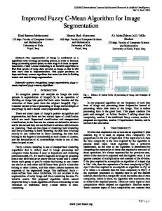
1 Regular quadtree10 and two types of quadtree representation, pointer-based representation or regular QT, and pointerless representation or linear QT: (a) structure of QT pointer; (b) the structure in (a) for the tree structure; (c) the corresponding linear list
Top-down and bottom-up partitioning strategy QT is typically represented by top-down or bottom-up methods.8,9,15 Top-down construction algorithm is first made to look whether a single leaf can represent the entire block or whether it must be divided into four sub-blocks. The same decision is made on the entire divided block that must be applied to its four sub-blocks as well, Each time, a block is checked to decide whether it needs further division or not, and so on. Bottom-up construction algorithms consist of decisions to merge. Accordingly, similar features blocks are merged to build a larger one; this process of block merging continues to build a larger block of same features. This approach builds a complete quadrant tree by assuming that all quadrants are non-uniform. Each time, a quadrant is evaluated for uniform features and four nodes corresponding to its four quarters are deleted from the QT. This strategy proceeds from bottom to root node.10
Types of QT data structure Shukla et al.10 employed two types for QT representation detailed as below.
Pointer-based QT representation (regular QT) The pointer-based QT representation or regular QT is implemented as a tree and has several advantages over other types of QTs. This representation is a tree structure with pointers to refer to nodes and for descriptor details. Figure 1a and b shows this kind of representation; Fig. 1a shows the structure of the node descriptor pointing to the four sons and Fig. 1b shows the representation of the tree. This type of representation provides an efficient means for navigating within the QT, so the set of operations (union, intersection and logic difference), or connected component labelling can be performed efficiently. Although a pointer structure may simplify any operation on the tree and speed up the access to its leaves, the memory requirements are unacceptable. As a result, the pointer-less QT representation got a considerable amount of interest.
Pointer-less representation (linear representation) Although it is the most natural way to represent a QT, the regular representation is inefficient as described by
Shukla et al.10 This data structure is in the form of a linear list consisting of the QT nodes in some traversed order. In this form of representation, the nodes are ordered so that the QT is in son’s nodes order. Each son immediately follows its parent node. Figure 1 shows the linear list of the tree. Information within the nodes is the same as that stored in the node descriptor of the regular QT. From this ordered list, it is shown that certain operations could be efficiently carried out upon the represented image. The space requirements for such a data structure are obviously much less than for the regular QT. The nodes in quadrant can only be visited in the order in which they are initially stored. The pointerless QT representation has gained an increasing use since it partially overcomes the previous two problems in many new researches. This representation can be classified into two groups: initial step represents the image’s nodes traversed in the QT and next step represents desired image as a group of terminal nodes.
Implementation of QT Non-squared images are the main problem in image segmentation by the QT,11 so Figs. 2 and 3 show the proposed pre-partitioning process to solve this problem. In this new process, the image is partitioned into tiles, which involves the handling of margin regions (i.e. some remainder parts existed on the right and bottom sides of the partitioned image). To solve this problem, the horizontal and vertical remainders are handled by implementing separate partitioning procedure. Tiles help the user to decode the part of the image (region of interest). After segmenting the image into tiles, the subdividing process is repeated recursively with each tile until the minimum size of the block is reached.12,16 Figure 3 illustrates the division process of QT: the process starts with the squared part of the image, then the vertical/horizontal parts are divided into 2T2162T21, 2T2262T22, …, 22622, where 2T is the size of partitioned blocks. The flowchart of the QT procedure (QThomogenity) is exhibited in Fig. 4, where the input represents the image, and the output, which is the structure tree, represents the dynamic segmentation of the image. This segmentation depends on the uniformity of the image. The main steps for the QT procedure in our programming are:
The Imaging Science Journal
2014
VOL
62
NO
1
57
Muhsin et al.
Improved QT image segmentation approach
2 Quadtree pre-partitioning process for the pre-image coding process
1. Check-homogeneity: the region of the leaf block is checked pixel by pixel to find the region uniformity. 2. QThomogeneity: this procedure is a recursive technique, which divides the heterogeneous region into four equal size sub-regions. 3. Set P (homogenous/heterogeneous): a pointer is set to indicate the uniformity (homogenous/heterogeneous) to the input region. The flowchart in Fig. 4 is started with partitioning the input image into blocks of max.-size, then for each block, the homogeneity level is determined, where the program tests the four sub-blocks, and checks whether the block is a leaf region (no more subdivision, level50), or not. When the block is not a leaf, then it is divided into four sub-blocks by applying QT procedure (recursion techniques). If any of the four sons is homogenous, then it will set the information of the subdivided region as homogenous point; otherwise, it proceeds by dividing it into sub-blocks. Building the link
3 Solving the problem of unsquared image
58
The Imaging Science Journal
2014
VOL
62
NO
1
list structure with this process saves the information of these sons during the recursion process. Each son should point to the homogeneity type of its corresponding region. The process of subdividing a block is illustrated in Fig. 5. The first block is (x22level,y22level,x,y), which is called the NW, the second (x,y22level,xz2level,y) represents the NE; the third is (x22level,y,x,yz2level) which corresponds to SW; and the last sub-block is (x,y,xz2level,yz2level) which is equal to SE. The previous process is a bottom-up construction algorithm. The algorithm begins with the sub-block (son block) size and if all relevant sub-blocks have common homogeneity, then they should be combined to produce parent (larger) block. Figure 6 shows the bottom-up process; the bottom-up uses the homogeneity criteria to merge son blocks to construct the parent block. Tables 1 and 2 show the data structure that has been used to save the attributes of the subdivided blocks. The
Muhsin et al.
Improved QT image segmentation approach
4 The flowchart of QThomogenity procedure
5 Quadtree block
data structure in Table 2 is used to register the information of each son (sub-block) and father (parent block). This structure is then transmitted to the decoder. The first structure (Table 1) is used in the second structure (Table 2). Algorithm 1 illustrates the use of these two structures. When the check-homogeneity procedure is used by the algorithm, it returns the D.type (D is structure-pair), then the D.type is referred to the colour of the block (D.Grey set to zero for
homogeneity, and D.Po is NULL), since it represents only this block. Algorithm (1) QT homogeneity procedure Input the region of the image; Max-depth: maximum depth of the partitioning, level: determine the depth division Table 1 Structure L-node N
Name
Comment
1 2 3
Type Grey Po
Buffer for grey value Homogeneity Pointer structure of L-node
Table 2 Structure pair
6 Bottom-up and top-down structures
N
Name
Comment
1 2 3 4
ATT Father Son Colour
Sonblock50, parentblock51 Pointer structure of L-node Array of pointer structure of L-node Buffer for grey value
The Imaging Science Journal
2014
VOL
62
NO
1
59
Muhsin et al.
Improved QT image segmentation approach
9 Re-quadtree for the inverse of quadtree partitioning
7 Changes of V and l in homogenous function
Output pointer that save the constructed tree (mapped QT), the stream of homogenous and heterogeneous blocks Variables x,y,i: index; P: pointer structure of pair for four node save; D,q,r,m: temporary structure pair Procedure Begin Input the Region-image(x,y) If level is the last level5Min_depth then DrHomogenous (x,y,bsize), Return (D) Else Levelrlevel-1 P[0]rQThomogenity(level,x-2level,y-2level,size); P[1]rQThomogenity (level,x, y-2level, size) P[2]rQThomogenity (level, x-2level,y,size); P[3]rQThomogenity (level,x,y,size) If the four sons have the same color and all are homogenous then return one of the four son Else qrCreate-node-pointer {*create a new position of type pointer structure *} Let q.attrNULL for all four children do (ir1 … 3) do if p[i] is homogenous then rrCreate-nodepointer, Let r.colorrp[i].type, All four sons of r is NULL (empty), Let r.attr1, r.fatherrq, q.son[i]rr
8 The flowchart of QThomogenity procedure
60
The Imaging Science Journal
2014
VOL
62
NO
1
Else {*not homogenous node*} If p[i] is not a leaf node then {*not leaf node*} p[i].fatherrq Else mrCreate-node-pointer, Let m.colorr0, and m.fatherrq For all four sons of m is NULL Let p[i].porm endelse Let q.son[i]rp[i].po endelse endfor D.po5q, return(D) endprocedure The homogeneity check is shown in Fig. 7. The first step is to calculate the variance of the input block. Then, variance is compared with threshold (Vhom) for homogeneity. When the variance exceeds the Vhom, it means that the block is homogenous; otherwise, it is not. The other criterion that is applied to determine the homogeneity of the block, is by counting the number of block elements (pixels) whose gray values is far from the mean of the tested block by a distance less than variance. Then the process finds the normalisation of the count. The lhom represents the door step to the homogenous block. Figure 8 shows the QT partitioning method applied on the ‘clown’ image, for different sets of (Vhom and lhom). Figure 9 shows the flowchart of the inverse QT procedure. In this flowchart, the input comes from different streams (mapping, heterogeneous blocks and homogenous blocks), while the output is represented by one image.
Muhsin et al.
10 Remainder partitioning
It is started with checking a 1-bit flag from the mapping stream (0 for heterogeneous block, 1 for homogenous). If it is homogenous, then it will read the components of the specific block (2level62level) from the homogenous stream; otherwise, the block is read from the heterogeneous stream. Figure 10 shows the solution for the problem of remainder (horizontal/vertical) part, after dividing the image into a region of 2level2162level21 and then constructing the QT. Algorithm (2) exhibits the steps of dividing the remanding bottom part, and the same procedure is followed to handle the right remaining blocks. Figure 11 declares the flowchart wrt (Ppointer, Level, xposition, yposition), which converts
Improved QT image segmentation approach
the QT pointers into file. The output map file has 0 for homogenous blocks and 1 for heterogeneous blocks. Algorithm (2): Vertical division for remainder part Input input image; maximum size of the block: minimum size of the block; width, height: the dimension of input image; Xsize: tile size; Output mapped contained the map of the image partitioning by the QT, it contains only 0 and 1 to represent the leaf node. the homogenous blocks; the heterogeneous blocks Variables noW: number of blocks in the vertical coordinate; restW: remained width from the vertical coordinate noH: number of blocks in the horizontal coordinate; G: pointer for input data image P: pointer to save the output map from QT partitioning Procedure Begin Let noWrwidth/Xsize; Let restWrwidth-(noW*Xsize) If there is block to be quad in remainder then For all the blocks in remained remainder do If restW ,. msize-1 then restWrrestW-2i; noHrhigh/2i {find the number of blocks in the horizontal to be square} For all the blocks in the horizontal (j50 to noH) do G5read_block (newW, 2i *j,2i); i i i i i P5QThomogeneity(i,2 ,2 ,2 ); Wrt (P,i,2 ,2 ) endfor endif endfor endif endprocedure
11 ‘Wrt’ recursive procedure
The Imaging Science Journal
2014
VOL
62
NO
1
61
Muhsin et al.
Improved QT image segmentation approach
Table 3 The important parameters in the research work N
Parameters
Comments
1
MaxQT partitioning
2 3
MinQT partitioning QT threshold
Different values (868–1286128) have been analysed Only one vale 464 Two thresholds have been used to have more control to find out homogenous and heterogeneous regions
Conclusion This paper has presented QT-based efficient approach to region desired information in image segmentation process. The proposed approach explores texture features that present in an image and provides a general framework to discriminate features for image segmentation. The weakness of the existing fixed size partitioning approaches lies in the fact that there are regions which are difficult to discriminate perfectly; however, the proposed QT approach does not need to be of uniform depth as well as it can region the desired information in a mixed image accurately. The selection of parameters values used in the segmentation should be chosen precisely, as these values has a great effect on the segmentation process. Accordingly, Table 3 exhibits the important parameters used in the representation process. As a result, the pointer-less QT representation (B type) gets a considerable amount of interest than the other ones. The A type of representation (regular QT) provides an efficient mean for navigating within the QT and the B type of representation gets a considerable amount of interest. The space requirements for such a data structure are obviously much less than for the A type representation, but the nodes for the quadrant in type B are only visited according to their initial order. Finally, the significance of the proposed approach is elaborated with the help of flowchart and diagrams in the paper.
Acknowledgements We express our deepest thanks and appreciation to the Deanship of Scientific Research at King Saud University Riyadh KSA for funding this research. We are also
62
The Imaging Science Journal
2014
VOL
62
NO
1
thankful to our colleague researchers for their valuable suggestions to improve this work.
References 1. Rad, A. E., Rahim, M. S. M., Rehman, A., Altameem, A. and Saba, T. Evaluation of current dental radiographs segmentation approaches in computer-aided applications. IETE Tech. Rev., 2013, 30, 210–222. 2. Rehman, A., Saba, T. and Sulong, G. An intelligent approach to image denoising. J. Theor. Appl. Inf. Technol., 2010, 17, 32–36. 3. Saba, T., Rehman, A. and Elarbi-Boudihir, M. Methods and strategies on off-line cursive touched characters segmentation: a directional review. Artif. Intell. Rev., 2011, doi: 10?1007/s10462011-9271-5. 4. Rehman, A. and Saba, T. Neural network for document image preprocessing. Artif. Intell. Rev., 2012, doi: 10?1007/s10462-0129337-z. 5. Saba, T. and Rehman, A. Effects of artificially intelligent tools on pattern recognition. Int. J. Mach. Learn. Cybern., 2013, 4, 155–162. 6. Rehman, A. and Saba, T. Document skew estimation and correction: analysis of techniques, common problems and possible solutions. Appl. Artif. Intell., 2011, 25, 769–787. 7. T. Saba, Al-Zorani, S. and Rehman, A. Expert system for offline clinical guidelines and treatment. Life Sci. J., 2012, 9, 2639–2658. 8. Balmelli, L. Kovacevic, J. and Vetterli, M. Quadtree for embedded surface visualization: constraints and efficient data structures, Proc. IEEE Int. Conf. on Image processing: ICIP 2009, Cairo, Egypt, November 2009, IEEE, Vol. 2, pp. 487–491. 9. Shukla, R., Dragotti, L., Do, M. and Vetterli, M. Improved quadtree algorithm based on joint coding for piecewise smooth image compression, Proc. IEEE Int. Conf. on Multimedia and expo: ICME 2002, Lausanne, Switzerland, August 2002, Swiss Federal Institute of Technology. 10. Shukla, R., Dragotti, P., Do, M. and Vetterli, M. Rate-distortion optimized tree-structure compression algorithms for piecewise polynomial images. IEEE Trans. Image Process., 2005, 14, 343– 359. 11. Rehman, A. and Saba, T. Performance analysis of segmentation approach for cursive handwritten word recognition on benchmark database. Digit Signal Process., 2011, 21, 486–490. 12. Saba, T. Sulong, G. and Rehman, A. Document image analysis: issues, comparison of methods and remaining problems. Artif. Intell. Rev., 2011, 35, 101–118. 13. Rehman, A and Saba, T. Features extraction for soccer video semantic analysis: current achievements and remaining issues. Artif. Intell. Rev., 2012, doi: 10?1007/s10462-012-9319-1. 14. Rehman, A. and Saba, T. Document skew estimation and correction: analysis of techniques, common problems and possible solutions. Appl. Artif. Intell., 2011, 25, 769–787. 15. Saba, T. and Altameem, A. Analysis of vision based systems to detect real time goal events in soccer videos. Appl. Artif. Intell., 2013, 27, 656–667. 16. Saba, T. and Alqahtani, F. A. Semantic analysis based forms information retrieval and classification. 3D Res., 2013, 4, 4.