order to physically bring the common sense of time to the stand alone node. .... âShoot messageâ, and (ii) kill the test by sending the broad cast âKill messageâ.
XIX IMEKO World Congress Fundamental and Applied Metrology September 611, 2009, Lisbon, Portugal
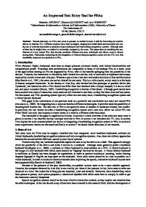
IMPROVED SYNCHRONIZING PROCEDURE OF PDAS TO DELIVERY THE COMMON SENSE OF THE TIME TO STAND ALONE MEASUREMENT INSTRUMENT Domenico Luca Carnì, Domenico Grimaldi, Francesco Lamonaca Department of Electronics, Computer and System Sciences, University of Calabria, 87036 Rende – CS, Italy {dlcarni, flamonaca, grimaldi}@deis.unical.it Abstract The paper proposes the optimized evolution of the previous procedure to synchronize the PDAs to the node of the Distributed Measurement System (DMS) in order to physically bring the common sense of time to the stand alone node. The improvements concern with (i) the selection of the clock node as reference one, (ii) the contemporaneous synchronization of all the involved PDAs, and (iii) the compensation of the effects of the drift of the electronic components on the number of system cycle after whom the control of the MI must be executed. The improvements pointed out originate from the practical evaluation of the performance of the previous synchronization procedure. The improved procedure meets the advantages of the synchronization based on the IEEE std 1588. Experimental tests are shown to validate the synchronization procedure and to highlight the advantages. Keywords: Synchronization, Distributed Measuerement System, Personal Digital Assistant. 1.
INTRODUCTION
The synchronization of the Measurement Instruments (MIs) connected to the Distributed Measurement System (DMS) needs that all the nodes involved must communicate to share a common synchronizing signal or message packets to adjust their node clocks. In some cases it is not possible to execute synchronized operations because (i) the network’s topology doesn’t provides continuous, reliable and stable link, wired or wireless, to the whole network [1][2], (ii) the installation of new wired or wireless links or repeaters should be expensive or not physically or technically possible, and (iii) the time constrain requires both fast and efficient solutions. A possibility is the use of embedded hardware in order to propagate the common sense of time based on GPS signal. However this solution can increase the cost of the system because requires the use of new, expensive and dedicated hardware. The increasing use of the Personal Digital Assistants (PDAs) makes possible to exploit these devices to drive and manage MIs or local DMS in synchronized manner to another MIs or DMSs, without wired or wireless connection
ISBN 978-963-88410-0-1 © 2009 IMEKO
to the previous ones. The solution proposed in [3] regards the synchronization of the PDA to common reference clock in order to bring “physically” this clock reference time to another MI or DMS inaccessible by the wired or wireless network. Therefore, the Master PC is previously synchronized into the DMS, through a boundary node. Successively, it extends the synchronization to the PDA with the suitable procedure. In order to synchronize the PDA to the Master PC, the IEEE std 1588 [4] can be taken into account. In this standard the protocol designed for the clock synchronization with microsecond or sub-microsecond accuracy is proposed. It is based on sharing the UDP packets marked with timestamp. Therefore, the accuracy of the synchronization is depending on the accuracy of the timestamp. In general, the PDA’s technology provides the time resolution of the order of millisecond [5]. As a consequence the achievable time resolution for synchronization is multiple of the millisecond, far from the clock synchronization of the microsecond guaranteed from the IEEE std 1588. This is a strong limitation to reach high accuracy in timestamp. For these reason in [3] was presented the procedure to synchronize the PDA based on the use of the system’s cycles in the place of the system time and the timestamp mechanism. System’s cycle depends directly on the CPU frequency of the PDA [6], and, consequently, the time resolution achievable is approximately of the order of nanoseconds/cycle. The synchronization procedure proposed in [3] can be reassumed in two fundamental steps: (i) the synchronization stage, and (ii) the measurement execution stage. In the synchronization stage, the Master PC receives the working frequency fi i=1,…, n from each of the n PDAs to be synchronized. The lower working frequency flw is selected and send to the n PDAs. Each PDA evaluates the own correction factor ci= fi /flw, i=1,…, n. In the measurement execution stage, the Master PC send to the n PDAs the number of cycle nc to be counted. Each PDA count nci=ci*nc, i=1,…, n, system cycles after whom it executes the control of the MI. In the paper the optimized evolution of the previous synchronization procedure [3] is proposed. The improvements pointed out originate from the practical evaluation of the performance of the previous
1203
synchronization procedure. The main improvements concern with: the reference clock. It is not yet the slower clock of PDAs involved into the synchronization, but the node clock. In this way, if the PC is equipped by real time Operating System, new PDA can be added into the group of the synchronized PDAs without to repeat the synchronization for all the PDAs; the reduction of the synchronization time. The contemporaneous synchronization of all the PDAs involved owing to the previous selection of the reference clock avoids the synchronization stage; the introduction of the look-up table and the regression line to establish the number of system cycles after whom executes the control of the MI. In this way for each PDA the drift of the electronic components can be taken into account, and the accurate correction factor can be evaluated depending on the number of cycles to be counted. The new improved procedure merges the advantages of the synchronization obtained by applying the IEEE std 1588 to the node clocks and the possibility to extend the common sense of time also in geographical area not reachable by the wired or wireless network. The paper is organized as follows. In order to made the paper self containing, beginning the time stamp accuracy into PDA is evaluated by experimental tests. The proposed synchronization procedure for PDA is presented. Experimental test results are shown to validate the synchronization procedure and to highlight their advantages.
Fig. 1. Interaction among two PDAs and the Master PC, and measurement of the time delay between the shoot time of the PDAs.
2.
EXPERIMENTAL TEST TO EVALUATE THE TIME STAMP ACCURACY INTO PDA
In order to measure the time stamp accuracy obtainable by the PDA, it is implemented the DMS shown in Fig1. On the PDAs run the same control program based on the check of the PDA clock. Fig.2 shows the block scheme of the operations performed by Master PC and the two PDA slaves. By means of the Master PC, the user: (i) set the time TS at which the two PDAs must generate the same signal on the earphone analog output, by sending the broad cast “Shoot message”, and (ii) kill the test by sending the broad cast “Kill message”. Each PDA in the case receives message “Shoot message” (i) saves the time shoot TS, (ii) checks in
Fig. 2. Block scheme of the interactyions among PDAs and the Master PC to send the shoot time to the PDAs.
1204
Fig. 3. Sequence of the commands planned to evaluate the delay introduced by the PDAs.
polling cycle the system time provided by the internal clock, and (iii) generates at the established time the output signal. In the case the received message is “Kill message”, each PDA aborts the execution of the program. The measure of the time delay between the two output signals is performed by using the Digital Storage Oscilloscope (DSO) Tektronix TDS7404 according to the command sequence shown in Fig.4. In particular, by using the VI of LabView™ implemented on the PC section of the DSO, the oscilloscope trigger is set to made it able to acquire the incoming signals. Successively, the Master sends a broadcast packet to the PDA Slave#1 and the PDA Slave#2. Both slaves count the established number of cycles. When they finish to count, PDA Slave#1 sends the signal to the trigger input of the oscilloscope and PDA Slave#2 sends the signal to the Ch1 of the oscilloscope. The delay is evaluated by the sample number occurring between the trigger and the cross of the established threshold by the acquired signal. Once set the trigger to 50% of the memory length, it needs to detect the first sample overcoming the threshold, only. In particular, denoted by i the half of the record length, j the index corresponding to the sample overcoming the threshold, dt the time between two samples, the time delay between the trigger and the signal is: Δt = |(i-j)*dt|.
The UDP packet loss is detected by taking into account that (i) if only one Slave is involved, it does not send the command to the DSO, and (ii) the Server receives the constant signals around the zero value. In the case both the Slaves are involved, the Server receives previous acquired signal. If the two PDA clocks have the same frequency and are not synchronized, the time difference between the two clocks is observed in the experimental results as the mean value of the synchronization delay different from zero. In this case, however, the interest of the test is devoted to evaluate the standard deviation. This last furnishes the accuracy of the timestamp obtainable by using the PDA clocks. The performed experimental tests highlight that by analyzing the time interval of 5s, the synchronization delay has mean value equal to 4 ms, and standard deviation equal to 390 ms. These results highlight the low accuracy of the PDA clocks, and the latency on the access to the clock. Therefore, by applying the synchronization techniques based on time stamped message passing the obtainable accuracy will be of the order of hundred ms, not suitable for measurement purposes according to the IEEE std 1588.
(1)
1205
3. PROPOSED SYNCHRONIZATION PROCEDURE Fig. 1 shows the block scheme of the proposed
Run software
Master (PC)
Run software
Slave (PDA) Shoot
Choose command
Synch
Synchronization Block
NO
Kill Process Receives the Time-shoot and the number of ripetitions
YES
Kill Message Sends the kill message
Sends the message with shoot information
Is Lookup table present?
Waits a master’s message
Saves a file with the results
It is the Kill message?
Shoot event
Shoot Message
Saves a file with the results
NO
YES
NO
Shoot procedure finished?
Calculates cycles, by lookup table, converts cycles to high priority by a correction factor
End Program
YES
Fig. 4. Block scheme of the programs running on Master PC and PDA to perform the synchronization.
procedure. The grey colored blocks refers to the previous procedure presented in [3]. The Master PC can be configured in three different ways: (i) synchronize mode, (ii) shoot mode, (iii) kill mode. In the first configuration, the synchronization between Master PC and slave PDAs is performed. In particular, the ith PDA creates an own lookup table with whom the number of cycle nc received from the Master PC is converted to nci. In the second configuration, the shoot time in which to execute the measure is established. Through master’s interface the shoot time is set and transmitted to the previous synchronized PDAs. Each PDAs, on the basis of the own lookup table, convert the data and executes the control procedure in order to perform the measure in the established time. The synchronization procedure based on look up table is shown in Fig.5. In order to build the look up table the following steps are performed. After the handshake procedure, the Master PC send to all Slaves, in broadcast modality, the number of cycles nc to be counted. Successively, the Master and all the PDA slaves start the local counter. When Master finishes the count sends the message to PDA slaves that stops the counter and stores in temporary variable the cycles spent in their own counting. Therefore the i-th PDA store the value nci. In this way the i-th PDA has the indirect information about the difference between the Master frequency and its own. This procedure is repeated with the same value of nc several times to obtain mean value and standard deviation of nci. The first row of look up table includes the value of nc and the mean value and standard deviation of nci. The other rows of the lookup table will be completed by changing the
value of nc. During the synchronization procedure, the messages between the Master PC and the PDA are transmitted by using Ad-Hoc WiFi network and the User Datagram Protocol (UDP). This is a protocol not connection oriented and it does not guarantee that the package arrival, or arrival in order, or the time in which they arrive. The absence of these controls helps speed transmission [7]. Based on this, sometimes, packets are lost, so it is necessary to introduce a mechanism of unlock. For this reason, when slave starts the synchronization procedure, more thread start: a thread as counter, a thread to receive UDP packet (using synchronous socket [7]-[8]) and another thread to unlock slave, if blocked. All these threads run with high priority. After synchronization the lookup table is stored in root directory as lt.txt and lt.dat (lt.dat is necessary to load the same lookup tables in the future). Through the data stored into the lookup table the interpolation curve of the midpoints is calculated to increase the synchronization resolution. Therefore, if the Master send to the PDAs the number of cycles nc not evaluated during the synchronization process, each PDA is able to correct it on the basis of the interpolation curve. In particular, if the value nci that the Master sends to the PDA is belonging in the range n1 n2 that are values present in the look up table, the PDA corrects nci in the value n~ci by:
n n n n n~1 n~ci ci 1~ 2 ~ 1 n2 n1
(2)
where n1 and n2 are the corrected values of n1 and n2 respectively.
1206
procedure. The DMS taken into account is shown in Fig.1. The sequence of the commands and operations planned to execute the tests are shown in Fig.3. The delay is evaluated according with the procedure shown in the second paragraph. In [3] it is shown that the shape of the output signal of the PDA influences the delay value. In particular, by using the system “beep” the mean value of the time delay is =6,7*10-4 s and the standard deviation is =8,6*10-4 s. By using the step signal constituted by 4,4 ksamples, the first 2,2 ksamples with value equal to zero and the second 2,2 ksamples with value equal to 250mV, is =2,0*10-4 s and =6,4*10-4 s. Therefore, the step signal is used in order to reduce the influence of the shape of the command signal on the time synchronization by PDAs. The trend of the mean value and the standard deviation of the synchronization delay depend mainly on the priority given to the control process respect to the concurrent process running into the PDA. In order to assess the advantages of the proposed synchronization procedure, in Fig.6 is shown the trend of the mean value and the standard Fig. 5. Synchronization procedure based on look up table and unlock procedures. deviation of the synchronization delay between the shoot time of After the synchronization the Master backs to the main menu the two PDAs versus the number of cycles, with and without to receive further commands, while the first PDA is ready to the synchronization procedure. It can be noted that the receive the shoot-message or the end-message. synchronization delay is practically constant once the PDAs In this step in the PDA algorithm all previous threads are are synchronized. In the contrary, without the killed and only one, in priority 0, is started. If a shoot message is synchronization the delay increases. received, the Slave send the WiFi packet or output signal after By comparing the results obtained in [3], the the number of cycles contained in the same shoot message. The introduction of the look-up table and the regression line has number of cycles is recalculated by using the regression line. permitted to reduce the synchronization time delay. If in the Master is chosen “end program”, the Master sends to slave the message that kills threads. 5. CONCLUSIONS When more PDAs are synchronized, the Master can send a message-shoot through broadcast to all PDAs that should shoot in the same time. In the paper is proposed the use of the Personal Digital Assistant (PDA) to share the common sense of time to stand alone Measurement Instruments (MIs). 4. EXPERIMENTAL TESTS Once synchronized to the common reference node clock of the Distributed Measurement System (DMS), the PDA is Experimental tests are performed in order to investigate used to physically bring the common sense of time to stand about (i) the behavior of the PDA on the basis of the alone MI. proposed synchronization procedure, and (ii) the The optimized evolution of the previous procedure to improvement obtained with the improved synchronization
1207
Fig. 6. Trend of the mean value and standard deviation of the synchronization delay between the shoot time of the two PDAs versus the number of cycles (a) without the synchronization, (b) with the previous synchronization procedure, and (c) with the proposed improved synchronization procedure.
synchronize the PDAs to the node of the DMS has been pointed out. The synchronization procedure is based on the system cycle in the place of the system frequency. The synchronization procedure works by (i) the selection of the clock node of the DMS as reference one, (ii) the contemporaneous synchronization of all the involved PDAs. The improvements concern with the introduction of the look-up table and the regression line to establish the number of system cycles after whom executes the control of the MI. In this way for each PDA the drift of the electronic components can be taken into account, and the accurate correction factor can be evaluated depending on the number of cycles to be counted. The improvements pointed out originate from the practical evaluation of the performance of the previous synchronization procedure. The improved procedure meets the advantages of the synchronization based on the IEEE std 1588. The results of experimental tests (i) validate the synchronization method pointed out, (ii) highlight the advantages, and (iii) justify the choice to perform the synchronization procedure on the basis of the system cycle in the place of the system frequency.
REFERENCES [1]
[2]
[3]
[4]
[5]
[6] [7] [8]
1208
U. Buy, A. D. Kshemkalyani, B. Sundararaman, “Clock synchronization for wireless sensor networks: a survey”, available on line: http://www.cs.uic.edu/~ajayk/ext/ClockSyncWSNsurvey.pdf, 2005. J. C. Tournier, X. Yin, “Improving Reliability of IEEE1588 in Electric Substation Automation”, Proc. of IEEE International Symposium on Precision Clock Synchronization for Measurement, Control and Communication (ISPCS), 2008. A. Barresi, D. Grimaldi, F.Lamonaca, “Delivery the Common Sense of the Time to Stand Alone Measurement Instrument by PDA”, Proc. of IEEE I2MTC 2009, Singapore, 5-7 May 2009. IEEE std. 1588-2002 “IEEE standard for a precise clock synchronization protocol for network measurement and control systems”, Published by The Institute of Electrical and Electronics Engineers, New York (USA),8 November 20002. P. Yaou, “Windows CE 3.0: Enhanced Real-Time Features Provide Sophisticated Thread Handling”, issue of MSDN Magazine, November 2000, available on line: http://msdn.microsoft.com/enus/magazine/bb985033.aspx. Dell™ Axim™ X50, Owner’s Manual 2004. Couch L, “Digital and Analog communication systems 5th ed.” Prentice Hall, 1997. http://www.alhem.net/Sockets.